EP3100833B1 - Saugvorrichtung und pneumatischer zylinder mit einem antirotationsmechanismus - Google Patents
Saugvorrichtung und pneumatischer zylinder mit einem antirotationsmechanismus Download PDFInfo
- Publication number
- EP3100833B1 EP3100833B1 EP16172259.0A EP16172259A EP3100833B1 EP 3100833 B1 EP3100833 B1 EP 3100833B1 EP 16172259 A EP16172259 A EP 16172259A EP 3100833 B1 EP3100833 B1 EP 3100833B1
- Authority
- EP
- European Patent Office
- Prior art keywords
- movable element
- main body
- engagement portion
- shoe
- contact
- Prior art date
- Legal status (The legal status is an assumption and is not a legal conclusion. Google has not performed a legal analysis and makes no representation as to the accuracy of the status listed.)
- Active
Links
Images


Classifications
-
- B—PERFORMING OPERATIONS; TRANSPORTING
- B25—HAND TOOLS; PORTABLE POWER-DRIVEN TOOLS; MANIPULATORS
- B25J—MANIPULATORS; CHAMBERS PROVIDED WITH MANIPULATION DEVICES
- B25J15/00—Gripping heads and other end effectors
- B25J15/06—Gripping heads and other end effectors with vacuum or magnetic holding means
- B25J15/0616—Gripping heads and other end effectors with vacuum or magnetic holding means with vacuum
-
- B—PERFORMING OPERATIONS; TRANSPORTING
- B65—CONVEYING; PACKING; STORING; HANDLING THIN OR FILAMENTARY MATERIAL
- B65G—TRANSPORT OR STORAGE DEVICES, e.g. CONVEYORS FOR LOADING OR TIPPING, SHOP CONVEYOR SYSTEMS OR PNEUMATIC TUBE CONVEYORS
- B65G47/00—Article or material-handling devices associated with conveyors; Methods employing such devices
- B65G47/74—Feeding, transfer, or discharging devices of particular kinds or types
- B65G47/90—Devices for picking-up and depositing articles or materials
- B65G47/91—Devices for picking-up and depositing articles or materials incorporating pneumatic, e.g. suction, grippers
-
- F—MECHANICAL ENGINEERING; LIGHTING; HEATING; WEAPONS; BLASTING
- F15—FLUID-PRESSURE ACTUATORS; HYDRAULICS OR PNEUMATICS IN GENERAL
- F15B—SYSTEMS ACTING BY MEANS OF FLUIDS IN GENERAL; FLUID-PRESSURE ACTUATORS, e.g. SERVOMOTORS; DETAILS OF FLUID-PRESSURE SYSTEMS, NOT OTHERWISE PROVIDED FOR
- F15B15/00—Fluid-actuated devices for displacing a member from one position to another; Gearing associated therewith
- F15B15/08—Characterised by the construction of the motor unit
- F15B15/14—Characterised by the construction of the motor unit of the straight-cylinder type
- F15B15/1414—Characterised by the construction of the motor unit of the straight-cylinder type with non-rotatable piston
Definitions
- This invention relates to anti-rotation mechanisms for elements which extend along a main axis and are movable in translation along said main axis.
- a first object of this invention is a device for the support of a pneumatically operated prehensile member, for example a suction cup, able to support the prehensile member and transmit the vacuum to it, and to be in turn connected to a support frame connected to the suction system.
- a pneumatically operated prehensile member for example a suction cup
- Said support devices are typically provided with a stem, at the end of which is connected the suction cup, able to translate with respect to a main body, intended for rigid connection with the support frame.
- the translation of the stem is essential for absorbing the shock due to the engagement of the suction cup on the part to be picked.
- such devices are typically provided with an anti-rotation mechanism, able to prevent rotation of the stem with respect to the main body.
- an anti-rotation mechanism able to prevent rotation of the stem with respect to the main body.
- a second object of this invention is a pneumatic cylinder provided with an anti-rotation mechanism.
- US 2006196354 A1 upon which the preamble of independent claim 17 is based, discloses a pneumatic cylinder with an anti-rotation mechanism based on the cooperation of a guide member rigidly connectable to a main body and bearing an extended contact surface, and a channel made in a stem.
- the purpose of this invention is to provide devices with an improved anti-rotation mechanism, in a first aspect a support device for pneumatic prehensile members, such as suction cups, and in a second aspect a pneumatic cylinder.
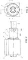
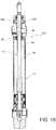
- reference number 1 globally indicates a support and vacuum supply device for a pneumatic prehensile member, such as for example a suction cup.
- the device 1 is suitable to mechanically support the prehensile member and to supply this with air in depression, so as to activate it for gripping a piece, for example a part being machined or to be handled or a component of a machine. Furthermore, the device 1 is suitable to be rigidly connected to a support frame, possibly together with a plurality of further support devices, each carrying a respective prehensile member.
- the device 1 comprises a main body 2 intended to be rigidly connected to the support frame.
- the main body 2 comprises a casing 3, for example made in a single piece of metallic material, typically steel, which extends axially between a rear surface 4, destined for coupling with the support frame, and an opposite front surface 6.
- the casing 3 is internally hollow, forming a casing chamber 7 passing between the rear surface 4 and the front surface 6.
- the main body 2 also comprises a sleeve 8, projecting axially from the rear surface 4 of the casing 3; preferably, said sleeve 8 and said casing 3 are made together in one piece.
- the sleeve 8 is also internally hollow, for a sleeve chamber 10 open at the rear and communicating anteriorly with the casing chamber 7.
- the main body 2 therefore has a single internal compartment, formed by the casing chamber 7 and the sleeve chamber 8, passing axially between the ends of the body 2.
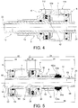
- the device 1 also comprises a movable element 12, at least partially housed in the main body 2, which extends along a translation axis X, between a rear end 14, projecting from the sleeve 8, and a front end 16, projecting from the front surface 6 of the casing 3.
- the movable element 12 is internally hollow, forming a pass-through power supply duct 18 that extends between the rear end 14 and the front end 16, flowing through a respective rear mouth 20 and a front mouth 22.
- the movable element 12 comprises a piston portion 24, partly received in the casing chamber 7 and partly in the sleeve chamber 10, comprising a stem 26 that passes through the sleeve chamber 10 and terminates at the rear end 14, and an annular shoulder 28, adjacent to the stem 26, projecting radially from this, received in the casing chamber 7.
- the piston portion 24 is sealingly slidable in the main body 2.
- the sleeve chamber 10 has at least a first sealing seat 30 in which is received a first sealing ring 32; the outer lateral surface of the stem 26 is at least partially sealingly engaged with the sealing ring 32.
- the shoulder 28 has at least a second sealing seat 34 in which is received a second sealing ring 36; the outer lateral surface of the shoulder 28 is thus sealingly slidable with respect to the lateral surface that delimits the casing chamber 7.
- the movable element 12 also comprises an extension portion 40, adjacent to the piston portion 24, partly received in the casing chamber 7 and partly projecting outwards from the front surface 6.
- the movable element 12 preferably provides a sensor seat 42, for example provided on the extension portion 40, adjacent to the shoulder 28 of the piston portion 24.
- the sensor seat 42 receives a magnet 42a of the device 1.
- the device 1 comprises a pair of detectors (not shown) mounted in predetermined fixed positions, spaced apart axially, in the main body 2, for example in the casing 3, suitable for detecting the position of the magnet 42a.
- the magnet and detectors realise an example of a detection means suitable for detecting the axial position assumed by the movable element 12, and in particular suitable to detect the positioning of the movable element 12 in the advanced limit position (end of exiting stroke from the front part of the main body 2) and in the retracted limit position (end of the return stroke).
- the extension portion 40 also includes a tang 44, for example adjacent the magnet seat, which extends axially towards the front mouth 22, so as to be accessible from the side of the front surface 6 of the main body 2, for example projecting anteriorly from the front surface 6.
- the piston portion 24 and the extension portion 40 are made in one piece, for example by machining by removal of chips from a bar.
- the main body 2 is at least partially closed at the front.
- the device 1 comprises a front cover 60, sealingly applied in the casing 3, in correspondence of the front surface 6; the cover 60 thus anteriorly delimits the casing chamber 7 and is maintained in position by a circlip 62.
- the cover 60 is pierced so as to allow the exit of the tang 44 of the movable element 12; preferably, the cover 60, in the pass-through hole for the tang, provides for at least a third sealing seat 66 which receives a third sealing ring 64, sealingly engaged with the tang 44.
- the device 1 is provided with an anti-rotation mechanism suitable to prevent the rotation of the movable element 12 about the main axis X.
- the anti-rotation mechanism includes at least one flattened surface 82, 84 formed on the outer lateral surface of an engagement portion 86 of the stem 26.
- the engagement portion 86 of the stem 26 is an end portion, having a predefined axial length, ending at the rear end 14 of said stem 26.
- Said engagement portion 86 has on the outer lateral surface of said one or more flattened surfaces 82,84, for example a pair of flattened surfaces 82,84, preferably parallel and opposed.
- the anti-rotation mechanism also provides at least one shoe 92a,94a,92b,94b applicable to the main body 2 of the device 1 and engageable with flattened surface 82,84 to achieve an anti-rotation constraint for the movable element 12.
- the anti-rotation mechanism is provided with a pair of shoes 92a,94a;92b,94b.
- the shoe 92a,94a,92b,94b is engaged with the sleeve 8 of the main body 2, and in particular is insertable in a slot 102a, 104a,102b,104b provided inside said sleeve.
- the anti-rotation mechanism is provided with a pair of slots 102a, 104a; 102b, 104b each for receiving the respective shoe 92a, 94a; 92b, 94b.
- the slot 102a, 104a, 102b, 104b passes through the thickness of the sleeve 8, so that the shoe 92a,94a,92b,194b inserted in it is visible from the outside and typically emerges to the outside.
- the shoe 92a,94a includes a contact portion 200 intended to come into contact with the respective flattened surface 82,84 of the engagement portion 86 of the stem 26 through a contact surface 202, typically flat.
- the contact surface 202 has a predetermined extension along the axial direction and a predetermined extension along a direction K orthogonal to this.
- the contact surface 202 is rectangular or square.
- the shoe 92a,94a comprises in addition an engagement portion 204, rigidly connected to the contact portion 200, projecting from the latter from the opposite side to the contact surface 202 and suitable to be inserted in the slot 102a,104a to form the anti-rotation constraint.
- the engagement portion 204 surmounts the contact portion 200 and extends outside it in the direction K orthogonal to the axial direction X.
- the engagement portion 204 has extension such as to be contained within the contact portion 200.
- the engagement portion 204 has the form of an approximately rectangular tongue, slightly curved circumferentially, rounded at the corners.
- the slot 102a, 104a has an outline such as to mate with shape-coupling with the engagement portion 204, for example, with tolerances of between 0 and +0.1 millimetres.
- the slot 102a,104a has a slot-shaped contour, circumferentially elongated.
- the shoe 92a, 94a is made in one piece, for example by machining by removal of chips.
- the shoe 92b,94b surmounts the contact portion 200 and has an extension such as to be contained within the contact portion 200 both in the direction K orthogonal to the axial direction X and in the axial direction X.
- the engagement portion 204 has the form of a circular cylinder, unloaded at the base to the junction with the contact portion 200.
- the slot 102a, 104a has an outline such as to mate with shape-coupling with the engagement portion 204, for example, with tolerances of between 0 and +0.1 millimetres.
- slot 102b,104b is a circular through hole.
- the shoe 92b, 94b is made in a single piece, for example by moulding.
- the shoe 92a, 94a, 92b, 94b is made of a self-lubricating material, for example a plastic material, such as an acetal resin.
- the device 1 also comprises pneumatic actuation means for the movement in translation of the movable element 12, so as to permit the approach and distancing along the main axis X of the prehensile member to the piece to be picked.
- the device 1 includes an alternating translation of the movable element 12; for this purpose, the main body includes a pair of connections 112,114, one that extends upstream and the other that extends downstream of the shoulder 28 of the piston portion 24, for operative connection with a pressurised air supply device.
- the device 1 includes return means, for example comprising a spring, which permanently influence the movable element 12 towards an end of stroke limit position, while the other end of stroke limit position is reachable by pneumatic actuation.
- return means for example comprising a spring, which permanently influence the movable element 12 towards an end of stroke limit position, while the other end of stroke limit position is reachable by pneumatic actuation.
- the support device 1 is applied to the pneumatic prehensile member, at the front end 16 of the movable element 12, fluidically connected with the rear mouth 20 for supply the vacuum.
- the main body 2 is rigidly connected to a support frame, in general together with a plurality of further support devices, each carrying a respective prehensile member.
- the movable element 12 is fluidically connected to a suction device through the rear mouth 20, so as to supply vacuum to the prehensile member through the supply duct 18.
- the device 1 is operatively connected with a pressurised air supply device for the translational actuation of the movable element 12.
- the support frame moved for example by a manipulator or a robot, is brought close to the piece to be picked.
- the device 1 is actuated pneumatically, so that the movable element 12 translates along the main axis X, bringing the prehensile member in contact, with thrust, on the gripping surface of the piece to be picked.
- the actuation of the suction device allows supplying vacuum to the suction cups through the supply duct 18 of the movable element 12.
- the suction cups thus adhere to the gripping surface and the piece can be lifted, moved or positioned according to the needs.
- the action of the shoes 92a,94a,92b,94b on the engagement portion 86 of the movable element 12 prevents the rotation of said movable element 12 with respect to the main axis X, thus avoiding the generation of torsion actions able to affect the adherence of the suction cups to the gripping surface.
- the support device according to this invention overcomes the drawbacks of the known art.
- the shoes have a very extensive contact surface with the engagement portion of the stem, due to which the torsion action is distributed over a large surface, significantly reducing the risk of breakage of the shoes.
- connection of the shoes to the main body is very reliable.
- the variant with extended engagement portion ( Figure 12 ) allows to unloading the actions that are generated on a wide contact surface, reducing the risk of breakage; such a variant, realised through machining, for example by the removal of chips, is more expensive, but it makes the device particularly suitable to support heavy loads.
- the invention allows further reducing the frequency and difficulty of maintenance, especially as regards greasing, since the shoes are made of self-lubricating material.
- the shoes are realised of different materials, depending on the temperature requirements or conditions of use of the device.
- the support device according to the invention has a particularly simple structure, so that assembly is facilitated, typically without the need for special tools.
- the realisation of the device does not require special machining or precision, and the engagement portion of the stem does not require tight tolerances, so that production costs are reduced.
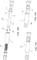
- the anti-rotation mechanism described above is also usable in further applications, such as for example a damped gripping device 300 ( Figures 14a to 14e ), provided with at least one shoe 302,304, acting on the engagement portion 86 made on the stem 26 of the movable element 12.
- the engagement portion 86 is provided with flattened surfaces 82,84; the shoe 302,304 is rigidly connectable to the main body 2; the movable element 12 is provided with the power supply conduit 18.
- the device 300 is provided with a spring 306, housed in the main body 2 and operating in compression between the main body 2 and the movable body 12, suitable to permanently influence the movable body 12 towards an end of stroke position, for example towards an advancement limit position.
- a spring 306 housed in the main body 2 and operating in compression between the main body 2 and the movable body 12, suitable to permanently influence the movable body 12 towards an end of stroke position, for example towards an advancement limit position.
- the spring 306 is mounted concentrically to the stem 26, outside of the engagement portion 86, for example between a shoulder of said engagement portion 86 and a locknut 308 fixed to the main body 2, for example by screwing, passed through by the movable element 12.
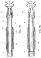
- a pneumatic cylinder 400 ( Figure 15 ), of simple or double effect, is provided with an anti-rotation mechanism.
- the cylinder 400 is provided with at least one shoe 402,404, acting on the engagement portion 86 made on the stem 26 of the movable element 12.
- the engagement portion 86 is provided with flattened surfaces 82,84; the shoe 302,304 is rigidly connectable to the main body 2.
Landscapes
- Engineering & Computer Science (AREA)
- Mechanical Engineering (AREA)
- Physics & Mathematics (AREA)
- Fluid Mechanics (AREA)
- General Engineering & Computer Science (AREA)
- Robotics (AREA)
- Actuator (AREA)
- Manipulator (AREA)
Claims (17)
- Stütz- bzw. Träger- und Vakuum- bzw. Saugantriebsvorrichtung (1, 300) für ein pneumatisches Greifglied, beispielsweise einen Saugnapf, umfassend:- einen Hauptkörper (2) zur Verbindung mit einem Stütz- bzw. Trägerrahmen;- ein bewegliches Element (12), das sich entlang einer Hauptachse (X) erstreckt und in Translation entlang der Hauptachse (X) beweglich ist, versehen mit einem Leistungsversorgungskanal (18), der hinten durch eine hintere Öffnung (20), die für die pneumatische Verbindung mit einer Saugvorrichtung bestimmt ist, und vorne durch eine vordere Öffnung (22) herauskommt, die für die pneumatische Verbindung mit dem Greifglied bestimmt ist;- einen Antirotationsmechanismus, der zumindest einen Eingriffsabschnitt (86) an einem Schaft (26) des beweglichen Elements (12) und zumindest einen Schuh (92a, 94a, 92b, 94b, 302, 304) umfasst, der starr mit dem Hauptkörper (2) verbindbar ist und eine erstreckte bzw. verlängerte Kontaktfläche (202) zum effektiven Kontakt mit dem Eingriffsabschnitt (86) des beweglichen Elements (12) trägt bzw. lagert, wodurch eine Antirotationsbeschränkung für das bewegliche Element (12) hergestellt ist;dadurch gekennzeichnet, dass der Eingriffsabschnitt (86) aus einem Paar gegenüberliegender bzw. entgegengesetzter und paralleler abgeflachter Flächen (82, 84) des Schafts (26) besteht und dass die verlängerte Kontaktfläche (202) aus einer flachen Fläche (202) besteht, die dazu bestimmt ist, mit der jeweiligen abgeflachten Fläche (82, 84) in Kontakt zu kommen.
- Vorrichtung nach Anspruch 1, wobei ein Paar Schuhe (92a, 94a, 92b, 94b, 302, 304) für den Betrieb an gegenüberliegenden bzw. entgegengesetzten Eingriffsabschnitten (86) bereitgestellt ist.
- Vorrichtung nach Anspruch 1 oder 2, wobei der Schuh aus einem Schlitz (102a, 102b, 104b, 104a) des Hauptkörpers (2) entfernbar ist.
- Vorrichtung nach Anspruch 3, wobei der Hauptkörper (2) eine Hülse (8) umfasst, die von einem Gehäuse (3) des Hauptkörpers (2) nach hinten vorspringt, wobei der Schaft (26) in Translation in der Hülse (8) geführt ist und der Schlitz in der Hülse hergestellt ist.
- Vorrichtung nach einem der vorhergehenden Ansprüche, wobei sich die abgeflachte Fläche bis zu dem hinteren Ende (14) des Schafts (26) erstreckt.
- Vorrichtung nach einem der vorhergehenden Ansprüche, wobei der Schuh einstückig hergestellt ist, beispielsweise aus selbstschmierendem Kunststoffmaterial, beispielsweise aus Acetalharz.
- Vorrichtung nach einem der vorhergehenden Ansprüche, wobei nach dem An- bzw. Aufbringen des Schuhs an dem Hauptkörper (2) die Kontaktfläche (202) eine vorbestimmte Erstreckung bzw. Ausdehnung in einer axialen Richtung (X) und eine vorbestimmte Erstreckung bzw. Ausdehnung in einer Richtung (K) orthogonal zu der axialen Richtung aufweist.
- Vorrichtung nach Anspruch 7, wobei die Kontaktfläche (202) rechteckig oder quadratisch ist.
- Vorrichtung nach Anspruch 7 oder 8, wobei der Schuh (92a, 94a) einen Kontaktabschnitt (200), der die Kontaktfläche (202) trägt bzw. lagert, und einen Eingriffsabschnitt (204) umfasst, der starr mit dem Kontaktabschnitt (200) verbunden ist, von letzterem von der gegenüberliegenden bzw. entgegengesetzten Seite zu der Kontaktfläche (202) vorspringt und geeignet ist, in den Hauptkörper (2) eingesetzt zu werden, um die Antirotationsbeschränkung zu bilden.
- Vorrichtung nach Anspruch 9, wobei der Eingriffsabschnitt (204) den Kontaktabschnitt (200) überragt und sich außerhalb davon in der Richtung (K) orthogonal zu der axialen Richtung (X) erstreckt.
- Vorrichtung nach Anspruch 10, wobei der Schlitz (102a, 104a) einen umfänglich bzw. umfangsmäßig länglichen Knopflochumriss darstellt, um mit dem Eingriffsabschnitt (204) des Schuhs (92a, 94a) in einer geformten Kopplung bzw. Formkopplung zu koppeln.
- Vorrichtung nach Anspruch 10, wobei der Eingriffsabschnitt (204), beispielsweise in Form eines Kreiszylinders, den Kontaktabschnitt (200) überragt und eine Erstreckung aufweist, um innerhalb des Kontaktabschnitts (200) sowohl in der Richtung (K) orthogonal zu der axialen Richtung (X) als auch in der axialen Richtung (X) enthalten zu sein.
- Vorrichtung nach Anspruch 12, wobei der Schlitz (102b, 104b) ein kreisförmiges Durchgangsloch ist.
- Vorrichtung (1) nach einem der vorhergehenden Ansprüche, wobei das bewegliche Element (12) pneumatisch beweglich ist.
- Vorrichtung (300) nach einem der vorhergehenden Ansprüche, wobei das bewegliche Element (12) gedämpft ist.
- Vorrichtung nach Anspruch 15, umfassend eine Feder (306), die unter Druck bzw. in Kompression zwischen dem Hauptkörper (2) und dem beweglichen Element (12) arbeitet, geeignet, das bewegliche Element dauerhaft in Richtung einer Endhubposition zu beeinflussen.
- Pneumatischer Zylinder (400), umfassend:- einen Hauptkörper (2);- ein bewegliches Element (12), das sich entlang einer Hauptachse (X) erstreckt und in Translation entlang der Hauptachse (X) pneumatisch beweglich ist;- einen Antirotationsmechanismus, der zumindest einen Eingriffsabschnitt (86) an einem Schaft (26) des beweglichen Elements (12) und zumindest einen Schuh (402, 404) umfasst, der starr mit dem Hauptkörper (2) verbindbar ist und eine erstreckte bzw. verlängerte Kontaktfläche (202) zum effektiven Kontakt mit dem Eingriffsabschnitt (86) des beweglichen Elements (12) trägt bzw. lagert, wodurch eine Antirotationsbeschränkung für das bewegliche Element (12) hergestellt ist;dadurch gekennzeichnet, dass der Eingriffsabschnitt (86) aus einem Paar gegenüberliegender bzw. entgegengesetzter und paralleler abgeflachter Flächen (82, 84) des Schafts (26) besteht und dass die verlängerte Kontaktfläche (202) aus einer flachen Fläche (202) besteht, die dazu bestimmt ist, mit der jeweiligen abgeflachten Fläche (82, 84) in Kontakt zu kommen.
Applications Claiming Priority (1)
| Application Number | Priority Date | Filing Date | Title |
|---|---|---|---|
| ITUB20151151 | 2015-06-04 |
Publications (2)
| Publication Number | Publication Date |
|---|---|
| EP3100833A1 EP3100833A1 (de) | 2016-12-07 |
| EP3100833B1 true EP3100833B1 (de) | 2020-11-04 |
Family
ID=54150549
Family Applications (1)
| Application Number | Title | Priority Date | Filing Date |
|---|---|---|---|
| EP16172259.0A Active EP3100833B1 (de) | 2015-06-04 | 2016-05-31 | Saugvorrichtung und pneumatischer zylinder mit einem antirotationsmechanismus |
Country Status (1)
| Country | Link |
|---|---|
| EP (1) | EP3100833B1 (de) |
Cited By (1)
| Publication number | Priority date | Publication date | Assignee | Title |
|---|---|---|---|---|
| RU218613U1 (ru) * | 2023-01-09 | 2023-06-01 | Общество с ограниченной ответственностью "Константа-2" | Пневмоцилиндр |
Families Citing this family (5)
| Publication number | Priority date | Publication date | Assignee | Title |
|---|---|---|---|---|
| JP6886895B2 (ja) * | 2017-08-25 | 2021-06-16 | 京セラ株式会社 | 吸着ノズル組み立て体 |
| DE112018006537T5 (de) * | 2017-12-22 | 2020-08-27 | GIMATIC S.r.l. | Aufhängungsvorrichtung für Saugnäpfe von Manipulatoren |
| CN108715346B (zh) * | 2018-07-06 | 2024-06-28 | 湖南德景源科技有限公司 | 一种匣体生产系统 |
| JP7748613B2 (ja) * | 2021-09-02 | 2025-10-03 | 株式会社アイシン | 変位検知装置 |
| CN114084705B (zh) * | 2021-11-03 | 2025-07-15 | 深圳市宏讯制造技术有限公司 | 一种吸嘴组件、抓取设备及位置调整方法 |
Citations (7)
| Publication number | Priority date | Publication date | Assignee | Title |
|---|---|---|---|---|
| FR1323164A (fr) | 1961-04-26 | 1963-04-05 | Festo Maschf Stoll G | Cylindre pour des moteurs actionnés par un agent de pression pneumatique ou hydraulique |
| US5193776A (en) | 1990-10-05 | 1993-03-16 | Smc Kabushiki Kaisha | Mechanism for locking angular movement of suction pad |
| EP0597207B1 (de) | 1992-11-12 | 1997-02-19 | Festo KG | Vorrichtung für den Längenausgleich von Vakuumsaugern |
| US20060196354A1 (en) | 2005-03-04 | 2006-09-07 | Festo Corporation | Linear drive with non-rotating piston |
| WO2008004850A1 (en) | 2006-07-05 | 2008-01-10 | Intotest Sdn. Bhd. | Collet head for placement machine |
| US20090020668A1 (en) | 2007-07-16 | 2009-01-22 | Giuseppe Maffeis | Suspension appliance for gripping devices |
| US8267449B2 (en) | 2009-03-11 | 2012-09-18 | Gimatic S.P.A. | Support device for prehensile members |
Family Cites Families (1)
| Publication number | Priority date | Publication date | Assignee | Title |
|---|---|---|---|---|
| US7281739B2 (en) * | 2004-09-01 | 2007-10-16 | Delaware Capital Formation, Inc. | Adjustable mount for vacuum cup with offset mounting post and swivel |
-
2016
- 2016-05-31 EP EP16172259.0A patent/EP3100833B1/de active Active
Patent Citations (7)
| Publication number | Priority date | Publication date | Assignee | Title |
|---|---|---|---|---|
| FR1323164A (fr) | 1961-04-26 | 1963-04-05 | Festo Maschf Stoll G | Cylindre pour des moteurs actionnés par un agent de pression pneumatique ou hydraulique |
| US5193776A (en) | 1990-10-05 | 1993-03-16 | Smc Kabushiki Kaisha | Mechanism for locking angular movement of suction pad |
| EP0597207B1 (de) | 1992-11-12 | 1997-02-19 | Festo KG | Vorrichtung für den Längenausgleich von Vakuumsaugern |
| US20060196354A1 (en) | 2005-03-04 | 2006-09-07 | Festo Corporation | Linear drive with non-rotating piston |
| WO2008004850A1 (en) | 2006-07-05 | 2008-01-10 | Intotest Sdn. Bhd. | Collet head for placement machine |
| US20090020668A1 (en) | 2007-07-16 | 2009-01-22 | Giuseppe Maffeis | Suspension appliance for gripping devices |
| US8267449B2 (en) | 2009-03-11 | 2012-09-18 | Gimatic S.P.A. | Support device for prehensile members |
Non-Patent Citations (2)
| Title |
|---|
| "FIPA Greifertechnik (End-of-Arm-Tooling)", FIPA CATALOGUE, 2012, pages 71, XP055752134 |
| "Suspensions", GIMATIC CATALOGUE, September 2014 (2014-09-01), pages 266 - 267, XP055752146 |
Cited By (1)
| Publication number | Priority date | Publication date | Assignee | Title |
|---|---|---|---|---|
| RU218613U1 (ru) * | 2023-01-09 | 2023-06-01 | Общество с ограниченной ответственностью "Константа-2" | Пневмоцилиндр |
Also Published As
| Publication number | Publication date |
|---|---|
| EP3100833A1 (de) | 2016-12-07 |
Similar Documents
| Publication | Publication Date | Title |
|---|---|---|
| EP3100833B1 (de) | Saugvorrichtung und pneumatischer zylinder mit einem antirotationsmechanismus | |
| US8801068B2 (en) | Apparatus and method for engaging and handling articles of manufacture | |
| US10307913B2 (en) | Robotic gripper | |
| US8919844B1 (en) | Gripper with actuator mounted displacement sensor | |
| US10507576B2 (en) | Industrial robot | |
| EP3370895B1 (de) | Stanzvorrichtung | |
| US9849597B2 (en) | Suction-type hand for drawing and holding workpiece | |
| CN113646130B (zh) | 托架、夹紧件和负压夹紧装置 | |
| CN110394823B (zh) | 一种机械手吸盘组件 | |
| EP4035849A1 (de) | Greifer | |
| CA2970018A1 (en) | Fluid application device | |
| CA2970100C (en) | Feeder mechanism for feeding mechanical fasteners | |
| EP3538469B1 (de) | Haltevorrichtung für ein pneumatisches greifelement | |
| CN215395264U (zh) | 一种基于视觉检测技术的机器人 | |
| GB2481530A (en) | Valve with integral bearing and spring in an air flow control device for a machine tool | |
| CN104999461A (zh) | 机械手移动模组机构 | |
| EP2411681B1 (de) | Vorgespanntes, einstellbares kugellagerführungssystem | |
| CN212071979U (zh) | 一种机器人浮动手爪结构 | |
| US9522421B2 (en) | Bar mounted tool adaptor | |
| CN217861289U (zh) | 防误触碰式末端执行器及其所应用的机器人 | |
| CN217996002U (zh) | 一种取料机构及其移动机构 | |
| CN106076735A (zh) | 一种一体化点胶移载综合工作台 | |
| CN112191455B (zh) | 涂胶设备 | |
| CN110294180A (zh) | 多工位同步贴标机械装置设备 | |
| CN107433612B (zh) | 一种全封闭式耐高温气动夹钳 |
Legal Events
| Date | Code | Title | Description |
|---|---|---|---|
| PUAI | Public reference made under article 153(3) epc to a published international application that has entered the european phase |
Free format text: ORIGINAL CODE: 0009012 |
|
| STAA | Information on the status of an ep patent application or granted ep patent |
Free format text: STATUS: THE APPLICATION HAS BEEN PUBLISHED |
|
| AK | Designated contracting states |
Kind code of ref document: A1 Designated state(s): AL AT BE BG CH CY CZ DE DK EE ES FI FR GB GR HR HU IE IS IT LI LT LU LV MC MK MT NL NO PL PT RO RS SE SI SK SM TR |
|
| AX | Request for extension of the european patent |
Extension state: BA ME |
|
| STAA | Information on the status of an ep patent application or granted ep patent |
Free format text: STATUS: REQUEST FOR EXAMINATION WAS MADE |
|
| 17P | Request for examination filed |
Effective date: 20170607 |
|
| RBV | Designated contracting states (corrected) |
Designated state(s): AL AT BE BG CH CY CZ DE DK EE ES FI FR GB GR HR HU IE IS IT LI LT LU LV MC MK MT NL NO PL PT RO RS SE SI SK SM TR |
|
| GRAP | Despatch of communication of intention to grant a patent |
Free format text: ORIGINAL CODE: EPIDOSNIGR1 |
|
| STAA | Information on the status of an ep patent application or granted ep patent |
Free format text: STATUS: GRANT OF PATENT IS INTENDED |
|
| INTG | Intention to grant announced |
Effective date: 20200608 |
|
| GRAS | Grant fee paid |
Free format text: ORIGINAL CODE: EPIDOSNIGR3 |
|
| GRAA | (expected) grant |
Free format text: ORIGINAL CODE: 0009210 |
|
| STAA | Information on the status of an ep patent application or granted ep patent |
Free format text: STATUS: THE PATENT HAS BEEN GRANTED |
|
| AK | Designated contracting states |
Kind code of ref document: B1 Designated state(s): AL AT BE BG CH CY CZ DE DK EE ES FI FR GB GR HR HU IE IS IT LI LT LU LV MC MK MT NL NO PL PT RO RS SE SI SK SM TR |
|
| REG | Reference to a national code |
Ref country code: GB Ref legal event code: FG4D |
|
| REG | Reference to a national code |
Ref country code: DE Ref legal event code: R026 Ref document number: 602016046999 Country of ref document: DE |
|
| PLBI | Opposition filed |
Free format text: ORIGINAL CODE: 0009260 |
|
| REG | Reference to a national code |
Ref country code: CH Ref legal event code: EP |
|
| REG | Reference to a national code |
Ref country code: AT Ref legal event code: REF Ref document number: 1330207 Country of ref document: AT Kind code of ref document: T Effective date: 20201115 |
|
| REG | Reference to a national code |
Ref country code: IE Ref legal event code: FG4D |
|
| REG | Reference to a national code |
Ref country code: DE Ref legal event code: R096 Ref document number: 602016046999 Country of ref document: DE |
|
| REG | Reference to a national code |
Ref country code: FI Ref legal event code: MDE Opponent name: GIMATIC S.R.L. |
|
| 26 | Opposition filed |
Opponent name: GIMATIC S.R.L. Effective date: 20201105 |
|
| REG | Reference to a national code |
Ref country code: DE Ref legal event code: R081 Ref document number: 602016046999 Country of ref document: DE Owner name: CAMOZZI AUTOMATION S.P.A., IT Free format text: FORMER OWNER: CAMOZZI S.P.A. SOCIETA' UNIPERSONALE, BRESCIA, IT |
|
| RAP2 | Party data changed (patent owner data changed or rights of a patent transferred) |
Owner name: CAMOZZI AUTOMATION S.P.A. |
|
| REG | Reference to a national code |
Ref country code: NL Ref legal event code: MP Effective date: 20201104 |
|
| REG | Reference to a national code |
Ref country code: AT Ref legal event code: MK05 Ref document number: 1330207 Country of ref document: AT Kind code of ref document: T Effective date: 20201104 |
|
| PG25 | Lapsed in a contracting state [announced via postgrant information from national office to epo] |
Ref country code: FI Free format text: LAPSE BECAUSE OF FAILURE TO SUBMIT A TRANSLATION OF THE DESCRIPTION OR TO PAY THE FEE WITHIN THE PRESCRIBED TIME-LIMIT Effective date: 20201104 Ref country code: GR Free format text: LAPSE BECAUSE OF FAILURE TO SUBMIT A TRANSLATION OF THE DESCRIPTION OR TO PAY THE FEE WITHIN THE PRESCRIBED TIME-LIMIT Effective date: 20210205 Ref country code: NO Free format text: LAPSE BECAUSE OF FAILURE TO SUBMIT A TRANSLATION OF THE DESCRIPTION OR TO PAY THE FEE WITHIN THE PRESCRIBED TIME-LIMIT Effective date: 20210204 Ref country code: RS Free format text: LAPSE BECAUSE OF FAILURE TO SUBMIT A TRANSLATION OF THE DESCRIPTION OR TO PAY THE FEE WITHIN THE PRESCRIBED TIME-LIMIT Effective date: 20201104 Ref country code: PT Free format text: LAPSE BECAUSE OF FAILURE TO SUBMIT A TRANSLATION OF THE DESCRIPTION OR TO PAY THE FEE WITHIN THE PRESCRIBED TIME-LIMIT Effective date: 20210304 |
|
| PG25 | Lapsed in a contracting state [announced via postgrant information from national office to epo] |
Ref country code: ES Free format text: LAPSE BECAUSE OF FAILURE TO SUBMIT A TRANSLATION OF THE DESCRIPTION OR TO PAY THE FEE WITHIN THE PRESCRIBED TIME-LIMIT Effective date: 20201104 Ref country code: AT Free format text: LAPSE BECAUSE OF FAILURE TO SUBMIT A TRANSLATION OF THE DESCRIPTION OR TO PAY THE FEE WITHIN THE PRESCRIBED TIME-LIMIT Effective date: 20201104 Ref country code: LV Free format text: LAPSE BECAUSE OF FAILURE TO SUBMIT A TRANSLATION OF THE DESCRIPTION OR TO PAY THE FEE WITHIN THE PRESCRIBED TIME-LIMIT Effective date: 20201104 Ref country code: IS Free format text: LAPSE BECAUSE OF FAILURE TO SUBMIT A TRANSLATION OF THE DESCRIPTION OR TO PAY THE FEE WITHIN THE PRESCRIBED TIME-LIMIT Effective date: 20210304 Ref country code: SE Free format text: LAPSE BECAUSE OF FAILURE TO SUBMIT A TRANSLATION OF THE DESCRIPTION OR TO PAY THE FEE WITHIN THE PRESCRIBED TIME-LIMIT Effective date: 20201104 Ref country code: PL Free format text: LAPSE BECAUSE OF FAILURE TO SUBMIT A TRANSLATION OF THE DESCRIPTION OR TO PAY THE FEE WITHIN THE PRESCRIBED TIME-LIMIT Effective date: 20201104 Ref country code: BG Free format text: LAPSE BECAUSE OF FAILURE TO SUBMIT A TRANSLATION OF THE DESCRIPTION OR TO PAY THE FEE WITHIN THE PRESCRIBED TIME-LIMIT Effective date: 20210204 |
|
| REG | Reference to a national code |
Ref country code: LT Ref legal event code: MG9D |
|
| PG25 | Lapsed in a contracting state [announced via postgrant information from national office to epo] |
Ref country code: HR Free format text: LAPSE BECAUSE OF FAILURE TO SUBMIT A TRANSLATION OF THE DESCRIPTION OR TO PAY THE FEE WITHIN THE PRESCRIBED TIME-LIMIT Effective date: 20201104 |
|
| PG25 | Lapsed in a contracting state [announced via postgrant information from national office to epo] |
Ref country code: SK Free format text: LAPSE BECAUSE OF FAILURE TO SUBMIT A TRANSLATION OF THE DESCRIPTION OR TO PAY THE FEE WITHIN THE PRESCRIBED TIME-LIMIT Effective date: 20201104 Ref country code: RO Free format text: LAPSE BECAUSE OF FAILURE TO SUBMIT A TRANSLATION OF THE DESCRIPTION OR TO PAY THE FEE WITHIN THE PRESCRIBED TIME-LIMIT Effective date: 20201104 Ref country code: SM Free format text: LAPSE BECAUSE OF FAILURE TO SUBMIT A TRANSLATION OF THE DESCRIPTION OR TO PAY THE FEE WITHIN THE PRESCRIBED TIME-LIMIT Effective date: 20201104 Ref country code: LT Free format text: LAPSE BECAUSE OF FAILURE TO SUBMIT A TRANSLATION OF THE DESCRIPTION OR TO PAY THE FEE WITHIN THE PRESCRIBED TIME-LIMIT Effective date: 20201104 Ref country code: CZ Free format text: LAPSE BECAUSE OF FAILURE TO SUBMIT A TRANSLATION OF THE DESCRIPTION OR TO PAY THE FEE WITHIN THE PRESCRIBED TIME-LIMIT Effective date: 20201104 Ref country code: EE Free format text: LAPSE BECAUSE OF FAILURE TO SUBMIT A TRANSLATION OF THE DESCRIPTION OR TO PAY THE FEE WITHIN THE PRESCRIBED TIME-LIMIT Effective date: 20201104 |
|
| PLAF | Information modified related to communication of a notice of opposition and request to file observations + time limit |
Free format text: ORIGINAL CODE: EPIDOSCOBS2 |
|
| PLAX | Notice of opposition and request to file observation + time limit sent |
Free format text: ORIGINAL CODE: EPIDOSNOBS2 |
|
| PG25 | Lapsed in a contracting state [announced via postgrant information from national office to epo] |
Ref country code: DK Free format text: LAPSE BECAUSE OF FAILURE TO SUBMIT A TRANSLATION OF THE DESCRIPTION OR TO PAY THE FEE WITHIN THE PRESCRIBED TIME-LIMIT Effective date: 20201104 |
|
| PG25 | Lapsed in a contracting state [announced via postgrant information from national office to epo] |
Ref country code: NL Free format text: LAPSE BECAUSE OF FAILURE TO SUBMIT A TRANSLATION OF THE DESCRIPTION OR TO PAY THE FEE WITHIN THE PRESCRIBED TIME-LIMIT Effective date: 20201104 Ref country code: AL Free format text: LAPSE BECAUSE OF FAILURE TO SUBMIT A TRANSLATION OF THE DESCRIPTION OR TO PAY THE FEE WITHIN THE PRESCRIBED TIME-LIMIT Effective date: 20201104 |
|
| PG25 | Lapsed in a contracting state [announced via postgrant information from national office to epo] |
Ref country code: SI Free format text: LAPSE BECAUSE OF FAILURE TO SUBMIT A TRANSLATION OF THE DESCRIPTION OR TO PAY THE FEE WITHIN THE PRESCRIBED TIME-LIMIT Effective date: 20201104 |
|
| PLBB | Reply of patent proprietor to notice(s) of opposition received |
Free format text: ORIGINAL CODE: EPIDOSNOBS3 |
|
| REG | Reference to a national code |
Ref country code: CH Ref legal event code: PL |
|
| GBPC | Gb: european patent ceased through non-payment of renewal fee |
Effective date: 20210531 |
|
| PG25 | Lapsed in a contracting state [announced via postgrant information from national office to epo] |
Ref country code: LI Free format text: LAPSE BECAUSE OF NON-PAYMENT OF DUE FEES Effective date: 20210531 Ref country code: MC Free format text: LAPSE BECAUSE OF FAILURE TO SUBMIT A TRANSLATION OF THE DESCRIPTION OR TO PAY THE FEE WITHIN THE PRESCRIBED TIME-LIMIT Effective date: 20201104 Ref country code: LU Free format text: LAPSE BECAUSE OF NON-PAYMENT OF DUE FEES Effective date: 20210531 Ref country code: CH Free format text: LAPSE BECAUSE OF NON-PAYMENT OF DUE FEES Effective date: 20210531 |
|
| REG | Reference to a national code |
Ref country code: BE Ref legal event code: MM Effective date: 20210531 |
|
| PG25 | Lapsed in a contracting state [announced via postgrant information from national office to epo] |
Ref country code: IE Free format text: LAPSE BECAUSE OF NON-PAYMENT OF DUE FEES Effective date: 20210531 Ref country code: GB Free format text: LAPSE BECAUSE OF NON-PAYMENT OF DUE FEES Effective date: 20210531 |
|
| PG25 | Lapsed in a contracting state [announced via postgrant information from national office to epo] |
Ref country code: IS Free format text: LAPSE BECAUSE OF FAILURE TO SUBMIT A TRANSLATION OF THE DESCRIPTION OR TO PAY THE FEE WITHIN THE PRESCRIBED TIME-LIMIT Effective date: 20210304 |
|
| PG25 | Lapsed in a contracting state [announced via postgrant information from national office to epo] |
Ref country code: BE Free format text: LAPSE BECAUSE OF NON-PAYMENT OF DUE FEES Effective date: 20210531 |
|
| REG | Reference to a national code |
Ref country code: DE Ref legal event code: R100 Ref document number: 602016046999 Country of ref document: DE |
|
| PLCK | Communication despatched that opposition was rejected |
Free format text: ORIGINAL CODE: EPIDOSNREJ1 |
|
| PG25 | Lapsed in a contracting state [announced via postgrant information from national office to epo] |
Ref country code: HU Free format text: LAPSE BECAUSE OF FAILURE TO SUBMIT A TRANSLATION OF THE DESCRIPTION OR TO PAY THE FEE WITHIN THE PRESCRIBED TIME-LIMIT; INVALID AB INITIO Effective date: 20160531 |
|
| PLBN | Opposition rejected |
Free format text: ORIGINAL CODE: 0009273 |
|
| STAA | Information on the status of an ep patent application or granted ep patent |
Free format text: STATUS: OPPOSITION REJECTED |
|
| PG25 | Lapsed in a contracting state [announced via postgrant information from national office to epo] |
Ref country code: CY Free format text: LAPSE BECAUSE OF FAILURE TO SUBMIT A TRANSLATION OF THE DESCRIPTION OR TO PAY THE FEE WITHIN THE PRESCRIBED TIME-LIMIT Effective date: 20201104 |
|
| P01 | Opt-out of the competence of the unified patent court (upc) registered |
Effective date: 20230525 |
|
| 27O | Opposition rejected |
Effective date: 20230202 |
|
| PG25 | Lapsed in a contracting state [announced via postgrant information from national office to epo] |
Ref country code: MK Free format text: LAPSE BECAUSE OF FAILURE TO SUBMIT A TRANSLATION OF THE DESCRIPTION OR TO PAY THE FEE WITHIN THE PRESCRIBED TIME-LIMIT Effective date: 20201104 |
|
| PG25 | Lapsed in a contracting state [announced via postgrant information from national office to epo] |
Ref country code: MT Free format text: LAPSE BECAUSE OF FAILURE TO SUBMIT A TRANSLATION OF THE DESCRIPTION OR TO PAY THE FEE WITHIN THE PRESCRIBED TIME-LIMIT Effective date: 20201104 |
|
| PGFP | Annual fee paid to national office [announced via postgrant information from national office to epo] |
Ref country code: DE Payment date: 20250523 Year of fee payment: 10 |
|
| PGFP | Annual fee paid to national office [announced via postgrant information from national office to epo] |
Ref country code: FR Payment date: 20250430 Year of fee payment: 10 |
|
| PG25 | Lapsed in a contracting state [announced via postgrant information from national office to epo] |
Ref country code: TR Free format text: LAPSE BECAUSE OF FAILURE TO SUBMIT A TRANSLATION OF THE DESCRIPTION OR TO PAY THE FEE WITHIN THE PRESCRIBED TIME-LIMIT Effective date: 20201104 |
|
| PGFP | Annual fee paid to national office [announced via postgrant information from national office to epo] |
Ref country code: IT Payment date: 20260306 Year of fee payment: 11 |