EP3100865A1 - Patronenartige tintenstrahlaufzeichnungsvorrichtung - Google Patents
Patronenartige tintenstrahlaufzeichnungsvorrichtung Download PDFInfo
- Publication number
- EP3100865A1 EP3100865A1 EP14880102.0A EP14880102A EP3100865A1 EP 3100865 A1 EP3100865 A1 EP 3100865A1 EP 14880102 A EP14880102 A EP 14880102A EP 3100865 A1 EP3100865 A1 EP 3100865A1
- Authority
- EP
- European Patent Office
- Prior art keywords
- cartridge
- lever
- liquid
- section
- recording device
- Prior art date
- Legal status (The legal status is an assumption and is not a legal conclusion. Google has not performed a legal analysis and makes no representation as to the accuracy of the status listed.)
- Granted
Links
Images


Classifications
-
- B—PERFORMING OPERATIONS; TRANSPORTING
- B41—PRINTING; LINING MACHINES; TYPEWRITERS; STAMPS
- B41J—TYPEWRITERS; SELECTIVE PRINTING MECHANISMS, i.e. MECHANISMS PRINTING OTHERWISE THAN FROM A FORME; CORRECTION OF TYPOGRAPHICAL ERRORS
- B41J2/00—Typewriters or selective printing mechanisms characterised by the printing or marking process for which they are designed
- B41J2/005—Typewriters or selective printing mechanisms characterised by the printing or marking process for which they are designed characterised by bringing liquid or particles selectively into contact with a printing material
- B41J2/01—Ink jet
- B41J2/17—Ink jet characterised by ink handling
- B41J2/175—Ink supply systems ; Circuit parts therefor
- B41J2/17566—Ink level or ink residue control
-
- B—PERFORMING OPERATIONS; TRANSPORTING
- B41—PRINTING; LINING MACHINES; TYPEWRITERS; STAMPS
- B41J—TYPEWRITERS; SELECTIVE PRINTING MECHANISMS, i.e. MECHANISMS PRINTING OTHERWISE THAN FROM A FORME; CORRECTION OF TYPOGRAPHICAL ERRORS
- B41J2/00—Typewriters or selective printing mechanisms characterised by the printing or marking process for which they are designed
- B41J2/005—Typewriters or selective printing mechanisms characterised by the printing or marking process for which they are designed characterised by bringing liquid or particles selectively into contact with a printing material
- B41J2/01—Ink jet
- B41J2/07—Ink jet characterised by jet control
- B41J2/075—Ink jet characterised by jet control for many-valued deflection
- B41J2/08—Ink jet characterised by jet control for many-valued deflection charge-control type
-
- B—PERFORMING OPERATIONS; TRANSPORTING
- B41—PRINTING; LINING MACHINES; TYPEWRITERS; STAMPS
- B41J—TYPEWRITERS; SELECTIVE PRINTING MECHANISMS, i.e. MECHANISMS PRINTING OTHERWISE THAN FROM A FORME; CORRECTION OF TYPOGRAPHICAL ERRORS
- B41J2/00—Typewriters or selective printing mechanisms characterised by the printing or marking process for which they are designed
- B41J2/005—Typewriters or selective printing mechanisms characterised by the printing or marking process for which they are designed characterised by bringing liquid or particles selectively into contact with a printing material
- B41J2/01—Ink jet
- B41J2/17—Ink jet characterised by ink handling
- B41J2/1721—Collecting waste ink; Collectors therefor
-
- B—PERFORMING OPERATIONS; TRANSPORTING
- B41—PRINTING; LINING MACHINES; TYPEWRITERS; STAMPS
- B41J—TYPEWRITERS; SELECTIVE PRINTING MECHANISMS, i.e. MECHANISMS PRINTING OTHERWISE THAN FROM A FORME; CORRECTION OF TYPOGRAPHICAL ERRORS
- B41J2/00—Typewriters or selective printing mechanisms characterised by the printing or marking process for which they are designed
- B41J2/005—Typewriters or selective printing mechanisms characterised by the printing or marking process for which they are designed characterised by bringing liquid or particles selectively into contact with a printing material
- B41J2/01—Ink jet
- B41J2/17—Ink jet characterised by ink handling
- B41J2/175—Ink supply systems ; Circuit parts therefor
- B41J2/17503—Ink cartridges
- B41J2/17506—Refilling of the cartridge
- B41J2/17509—Whilst mounted in the printer
-
- B—PERFORMING OPERATIONS; TRANSPORTING
- B41—PRINTING; LINING MACHINES; TYPEWRITERS; STAMPS
- B41J—TYPEWRITERS; SELECTIVE PRINTING MECHANISMS, i.e. MECHANISMS PRINTING OTHERWISE THAN FROM A FORME; CORRECTION OF TYPOGRAPHICAL ERRORS
- B41J2/00—Typewriters or selective printing mechanisms characterised by the printing or marking process for which they are designed
- B41J2/005—Typewriters or selective printing mechanisms characterised by the printing or marking process for which they are designed characterised by bringing liquid or particles selectively into contact with a printing material
- B41J2/01—Ink jet
- B41J2/17—Ink jet characterised by ink handling
- B41J2/175—Ink supply systems ; Circuit parts therefor
- B41J2/17503—Ink cartridges
- B41J2/17513—Inner structure
-
- B—PERFORMING OPERATIONS; TRANSPORTING
- B41—PRINTING; LINING MACHINES; TYPEWRITERS; STAMPS
- B41J—TYPEWRITERS; SELECTIVE PRINTING MECHANISMS, i.e. MECHANISMS PRINTING OTHERWISE THAN FROM A FORME; CORRECTION OF TYPOGRAPHICAL ERRORS
- B41J2/00—Typewriters or selective printing mechanisms characterised by the printing or marking process for which they are designed
- B41J2/005—Typewriters or selective printing mechanisms characterised by the printing or marking process for which they are designed characterised by bringing liquid or particles selectively into contact with a printing material
- B41J2/01—Ink jet
- B41J2/17—Ink jet characterised by ink handling
- B41J2/175—Ink supply systems ; Circuit parts therefor
- B41J2/17503—Ink cartridges
- B41J2/1752—Mounting within the printer
- B41J2/17523—Ink connection
-
- B—PERFORMING OPERATIONS; TRANSPORTING
- B41—PRINTING; LINING MACHINES; TYPEWRITERS; STAMPS
- B41J—TYPEWRITERS; SELECTIVE PRINTING MECHANISMS, i.e. MECHANISMS PRINTING OTHERWISE THAN FROM A FORME; CORRECTION OF TYPOGRAPHICAL ERRORS
- B41J2/00—Typewriters or selective printing mechanisms characterised by the printing or marking process for which they are designed
- B41J2/005—Typewriters or selective printing mechanisms characterised by the printing or marking process for which they are designed characterised by bringing liquid or particles selectively into contact with a printing material
- B41J2/01—Ink jet
- B41J2/17—Ink jet characterised by ink handling
- B41J2/175—Ink supply systems ; Circuit parts therefor
- B41J2/17503—Ink cartridges
- B41J2/17553—Outer structure
Definitions
- the present invention relates to a cartridge-type inkjet recording device.
- Patent Literature 1 mentions that "a vessel 1 is liquid-tightly connected to an ink system by pressing a connector 7 against an adapter 3 in an axial direction. Then, ink or a solvent in the vessel 1 flows into the ink system through a connecting section and supply of desired liquid is performed.”
- Patent Literature 2 describes "a connector device including a fixing section including, on a lower surface side, a plurality of connecting pipes that can be hermetically attached to and removed from a fluid outlet/inlet pipe during mounting and demounting of a cartridge, a movable table including a flange holding section that holds a horizontal flange such that the fluid outlet/inlet pipe is aligned with the connecting pipes, a guiding mechanism including two elongated members crossing in an X shape and pivotally attached to each other in a crossing point in the center to restrain the movable table to be movable in the vertical direction, pins attached to end portions of the elongated members, and horizontal slots respectively provided on side surfaces of the fixing section and the movable table to horizontally guide the pins, and a cam slot for moving a cam pin fixed to the movable table up and down, the cam slot being an operation lever pivotally attached to the fixing section at one end portion and including
- the replacement-type liquid vessel described in Patent Literature 1 needs to be pressed in the axial direction in order to connect the replacement-type liquid vessel to the adapter on the main body side.
- a large pressing force is necessary depending on assembly accuracy of the replacement-type liquid vessel and the adapter.
- the connection is likely to be difficult by manual work.
- a replacement-type vessel is replaced in a housing of an inkjet recording device and when replacement work needs to be performed in a narrow place, in the connection in the axial direction, it is also likely that a sufficient pressing force cannot be applied by manual work.
- Patent Literature 2 describes the connector device for connecting a cartridge of a filter. Patent Literature 2 mentions that it is possible to move the filter in the vertical direction and connect the filter to a connector by setting the filter and pushing down the operation lever. However, concerning alignment in the connection of the filter and the connector, it is necessary to push in the filter along a guiderail of the connector device and accurately move the filter to a predetermined position. When the filter is not pushed in to the predetermined position, it is likely that the filter is not properly connected.
- an object of the present invention is to provide a cartridge-type inkjet recording device capable of accurately and easily connecting a cartridge-type replenishing liquid bottle and an inkjet recording device.
- An example of the means is a cartridge-type inkjet recording device including a liquid reservoir to which a replenishing liquid bottle is removably attachable.
- the liquid reservoir includes a liquid replenishment opening for replenishing liquid from the cartridge-type replenishing liquid bottle, a cam that is provided on the periphery of the liquid replenishment opening, engages with a portion of the cartridge-type replenishing liquid bottle, and moves the cartridge-type replenishing liquid bottle in the vertical direction, and a cam operation section that operates the cam.
- a cartridge-type inkjet recording device capable of accurately and easily connecting a cartridge-type replenishing liquid bottle and an inkjet recording device.
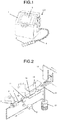
- Fig. 1 is a perspective view showing an inkjet recording device 100.
- the inkjet recording device 100 includes a main body 1, on the outside of which an operation display section 3 is provided, and a printing head 2.
- the main body 1 and the printing head 2 are connected by a conduit 4.
- ink in an ink tank 18 is sucked and pressurized by a pump 25 and discharged from a nozzle 8 as an ink column 7.
- the nozzle 8 includes an electrostrictive element 9. Vibration is applied to the ink at a predetermined frequency to convert the ink column 7 discharged from the nozzle 8 into particles. Consequently, the number of ink particles 10 to be generated is determined by a frequency of an excitation voltage applied to the electrostrictive element 9 and is the same number as the frequency.
- a voltage having magnitude corresponding to printing information is applied to the ink particles 10 by a charging electrode 11, whereby electric charges are given to the ink particles 10.
- the ink particles 10 charged by the charging electrode 11 receive force proportional to a charging amount and deflect, fly toward a printing target object 13, and impact on the printing target object 13.
- an impact position in a deflecting direction of the ink particles 10 changes according to the charging amount.
- a production line moves the printing target object 13 in a direction orthogonal to the deflecting direction. Consequently, it is possible to impact the particles in the direction orthogonal to the deflecting direction as well.
- a character is formed by a plurality of impacted particles to perform printing.
- the ink particles 10 not used for the printing linearly fly between the deflection electrodes 12. After being captured by a gutter 14, the ink particles 10 are collected in the main ink tank 18 through a route.
- the inkjet recording device 100 is installed in, for example, a production line in a factory where foods, drinks, and the like are produced.
- the main body 1 is set in a position where a user can operate the main body 1.
- the printing head 2 is set in a position where the printing head 2 can approach the printing target object 13 fed on the production line such as a belt conveyor 15.
- an encoder 16 that outputs a signal corresponding to the feeding speed to the inkjet recording device 100 and a printing sensor 17 that detects the printing target object 13 and outputs a signal for instructing the inkjet recording device 100 to perform printing are set.
- the encoder 16 and the printing sensor 17 are connected to a not-shown control section in the main body 1.
- the control section controls, according to the signals from the encoder 16 and the printing sensor 17, a charging amount and charging timing for the ink particles 10 discharged from the nozzle 8, causes the ink particles 10, which are charged and deflected while the printing target object 13 passes the vicinity of the printing head 2, to adhere to the printing target object 13, and performs printing.
- Fig. 4 is an explanatory diagram showing an overall route configuration of the inkjet recording device 100.
- the main body 1 includes the main ink tank 18 that stores ink to be circulated.
- the main ink tank 18 includes a liquid level sensor 38 that detects whether the liquid in the main ink tank 18 has reached a reference liquid level, which is an amount appropriate for the liquid in the main ink tank 18 to be stored on the inside of the main ink tank 18.
- the main ink tank 18 is connected to a viscometer 21, which is a drop-type viscometer for measuring the viscosity of ink, via a route 101 for circulating the ink.
- the viscometer 21 is connected to, via a route 102, an electromagnetic valve 22 that performs opening and closing of a route.
- the electromagnetic valve 22 is connected to, via a route 103, the pump 25 served for suction and pumping of ink and a solvent.
- the pump 25 is connected to, via a route 104, a filter 28 for removing foreign matters mixed in the ink.
- the filter 28 is connected to, via a route 105, a pressure reducing valve 30 that adjusts the ink pumped from the pump 25 to pressure appropriate for performing printing.
- the pressure reducing valve 30 is connected to, via the route 106, a pressure sensor 31 for detecting the pressure of the ink.
- the pressure sensor 31 is connected to, via a route 107 passing through the conduit 4, the nozzle 8 provided in the printing head 2 and including a discharge opening for discharging the ink.
- the charging electrode 11 In an ink discharge direction of the nozzle 8, the charging electrode 11 is disposed that charges the ink particles 10 with a charging amount corresponding to character information to be printed with the ink particles 10 discharged from the nozzle 8.
- the deflection electrodes 12 In a flying direction of the ink particles 10 charged by the charging electrode 11, the deflection electrodes 12 are disposed that generate an electric field for deflecting the charged ink particles 10.
- the gutter 14 On the ink flying direction side of the deflection electrodes 12, the gutter 14 is disposed that captures the ink particles 10 linearly flying without being charged and deflected because not used for printing.
- the gutter 14 is connected to, via a route 108 passing through the conduit 4, a filter 29 for removing foreign matters mixed in the ink disposed in the main body 1.
- the filter 29 is connected to, via a route 109, a collection pump 26 that sucks the ink particles 10 captured by the gutter 14.
- the collection pump 26 collects, via a route 110, the sucked ink particles 10 in the main ink tank 18.
- an exhaust opening 32 is provided in the main body 1.
- the exhaust opening 32 is connected to the main ink tank 18 via a route 150.
- a volatilized solvent component in the ink is exhausted to the outside of the main body 1 via the route 150.
- the main body 1 includes a solvent reservoir 20 that stores a solvent for eliminating contamination by the ink, which occurs in the nozzle 8, and adjusting the concentration of the ink.
- the solvent reservoir 20 is connected to, via the route 111, a pump 27 that performs suction and pumping of the solvent.
- the pump 27 is connected to, via a route 112, an electromagnetic valve 24 that performs opening and closing of a route.
- the electromagnetic valve 24 is connected to the main ink tank 18 via a route 113.
- the main body 1 includes an auxiliary ink reservoir 19 that stores ink to be replenished.
- the auxiliary ink reservoir 19 is connected to, via a route 120, an electromagnetic valve 23 that performs opening and closing of a route.
- the electromagnetic valve 23 is connected to the route 103 via a route 121.
- a cartridge-type replenishing liquid bottle 600 is removably attachable to the auxiliary ink reservoir 19 and the solvent reservoir 20. An attaching and removing configuration of the replenishing liquid bottle 600 is explained below.
- Fig. 5 is an example of a structural drawing for connecting the replenishing liquid bottle 600 to the auxiliary ink reservoir 19 or the auxiliary makeup reservoir 20 on the main body 1 side.
- the auxiliary ink reservoir 19 or the makeup reservoir 20 is set in the main body 1.
- a replenishing operation is performed in the inkjet recording device 100.
- the auxiliary ink reservoir 19 and the makeup reservoir 20 have the same bottle drawing-in configuration. Only the auxiliary ink reservoir 19 is explained here.
- the auxiliary ink reservoir 19 includes a liquid replenishment opening 501 and an atmospheric air opening 502.
- the liquid replenishment opening 501 is a connection opening to the replenishing liquid bottle 600.
- a sensor for detecting a liquid level in the auxiliary ink reservoir is attached to the atmospheric air opening 502.
- An adapter 506 connected to the replenishing liquid bottle 600 is provided on the periphery of the liquid replenishment opening 501. Not-shown bosses are provided at left and right both ends of the adapter 506. Lever cams 503 are provided in the bosses. Further, an operation lever 504 is attached to the lever cams 503 as an operation section that operates the lever cams 503. The lever cams 503 are operated by the operation lever 504 to connect the replenishing liquid bottle 600 to the auxiliary ink reservoir 19.
- a lever positioning plate 505 is provided at the lower end of the auxiliary ink reservoir 19.
- the replenishing liquid bottle 600 is fixed and positioned by the operation lever 504 and the lever positioning plate 505 not to topple when the replenishing liquid bottle 600 is connected to the auxiliary ink reservoir 19.
- a connection method for the auxiliary ink reservoir 19 and the replenishing liquid bottle 600 is explained below.
- an operation section that operates the lever cams 503 is the operation lever 504.
- a cam operation section is not limited to this mechanism.
- the cam operation section may be a mechanism that applies, when the replenishing liquid bottle 600 is connected, stress to the replenishing liquid bottle 600 from above the replenishing liquid bottle 600 to operate the cam.
- the cam operation section may be operated as a configuration in which the control section can automatically control the operation of the cam itself.
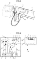
- Fig. 6(a) is an overall view of the replenishing liquid bottle 600.
- Fig. 6(b) is an enlarged view of a connecting section of the replenishing liquid bottle 600 and the auxiliary ink reservoir 19.
- Ink or a solvent is stored in a liquid storing section 601 of the replenishing liquid bottle 600.
- a bottle cap 602 is attached to a bottle opening of the liquid storing section 601.
- Bosses 603 are provided in a part of the liquid storing section 601 and integrated with the liquid storing section 601. The bosses 603 are used when the liquid storing section 601 is connected to the auxiliary ink reservoir 19. Therefore, resin is filled in the insides of the bosses 603 to secure strength of the bosses 603.
- the bottle cap 602 attached to the replenishing liquid bottle 600 forms an opening section in a cap top surface 605. Therefore, when the replenishing liquid bottle 600 is not used, as shown in Fig. 6(b) , intrusion of dust into the inside of the replenishing liquid bottle 600 can be prevented by attaching an over-cap 606.
- a protrusion 607 on the inside of the over-cap 606 is pushed in and fit with a protrusion 604 on the outer side of the bottle cap 602. It is possible to prevent a leak and smell of the remaining ink by attaching the over-cap 606 to the replenishing liquid bottle 600 after use.
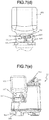
- Fig. 7(a) and Fig. 7(b) are state diagrams before connection to the main body side.
- Fig. 7(a) is a diagram showing a direction in which the replenishing liquid bottle 600 is connected to the auxiliary ink reservoir 19.
- Fig. 7(b) is a diagram in which the replenishing liquid bottle 600 is set in the auxiliary ink reservoir 19.
- the replenishing liquid bottle 600 is disposed on the upper surface of the adapter 506 with the cap top surface 605 facing downward. Thereafter, the replenishing liquid bottle 600 is brought close to the liquid replenishment opening 501.
- a recessed section is provided at a distal end portion of the lever cam 503. It is possible to guide the replenishing liquid bottle 600 to a connectable state by moving the boss 603 along a slope guide 700 that forms one sidewall surface of the recessed section.
- the boss 603 can be temporarily placed on a flat section 701 corresponding to a bottom surface section of the recessed section of the lever cam 503 and positioned.
- the replenishing liquid bottle 600 is brought into a preparation state in which the replenishing liquid bottle 600 is prepared for being drawn into and connected to the auxiliary ink reservoir 19.
- Fig. 7(c) is a state diagram halfway in the connection to the main body side.
- the operation lever 504 is pushed downward. Since the operation lever 504 is connected to the lever cam 503, when the operation lever 504 is pushed downward, it is possible to cause the lever cam 503 to perform a rotating action with a rotating shaft 507 being as an axis.
- a guide groove 704 is provided on the inner side surface of the lever cam 503.
- the guide groove 704 communicates with the other sidewall surface on the opposite side of the slope guide 700 of the recessed section of the lever cam 503.
- the lever cam 503 rotates.
- the boss 603 of the replenishing liquid bottle 600 is guided by the guide groove 704 from the flat section 701 of the recessed section of the lever cam 503 to move along the guide groove 704.
- the guide in the vertical direction is performed by engagement of the boss 603 of the replenishing liquid bottle 600 and the U-shaped groove 702 provided on the wall surface on which the liquid replenishment opening 501 of the adapter 506 is formed.
- the guide in the vertical direction may be performed by engagement of the outer side surface of the bottle cap 602 of the replenishing liquid bottle 600 and the wall inner side surface of the adapter 506.
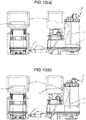
- Figs. 7(d) and 7(e) are state diagrams during connection to the main body side.
- Fig. 7(d) is a detailed structure of a connection state of the replenishing liquid bottle 600 and the auxiliary reservoir 19.
- Fig. 7(e) is an overall view in the connection state of the replenishing liquid bottle 600 and the auxiliary reservoir 19.
- the boss 603 stops at the lower end of the U-shaped groove 702 as shown in Fig. 7(d) .
- the operation lever 504 is positioned by the lever positioning plate 505 as shown in Fig. 7(e) .
- the operation lever 504 may be controlled to automatically operate.
- This embodiment is a configuration example for further accurately and easily carrying out alignment of the replenishing liquid bottle 600 with respect to the auxiliary ink reservoir 19 in addition to the configuration of the first embodiment.
- Fig. 9 is a diagram for explaining connection of the replenishing liquid bottle 600 and the auxiliary ink reservoir 19 in a second embodiment.
- a rib 900 is provided in the auxiliary ink reservoir 19 and a recessed section 901 is provided on a side surface of the replenishing liquid bottle 600.
- the replenishing liquid bottle 600 is set on the upper surface of the liquid replenishment opening 501 in a state in which the bottle cap 602 faces downward.
- the rib 900 interferes with the recessed section 901, it is possible to set the replenishing liquid bottle 600 in a position of a state in which the replenishing liquid bottle 600 can be drawn into the auxiliary ink reservoir 19.
- This embodiment is a configuration example incorporating a lock function of the operation lever 504 at the time when the replenishing liquid bottle 600 is set in the auxiliary ink reservoir 19 in addition to the configuration of the first embodiment.
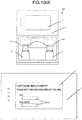
- Fig. 10(a) is a diagram of an unlocked state by the lock mechanism of the operation lever 504.
- Fig. 10(b) is a diagram of a locked state by the lock mechanism of the operation lever 504.
- Fig. 10(c) is a diagram for explaining a locking operation of the lock mechanism of the operation lever 504.
- Fig. 10(d) is a diagram for explaining an unlock code input in the unlocking of the lock mechanism of the operation lever 504.
- a solenoid lock 902 is provided near the lower end portion of the operation lever 504 as the lock mechanism to prevent the operation lever 504 from moving from a predetermined position, for example, a position where the operation lever 504 is fixed by the lever positioning plate 505.
- a setting position of the solenoid lock 902 only has to be a position on the operation lever 504 at the time when the operation lever 504 is positioned by the lever positioning plate 505, that is, only has to be a position where the operation lever 504 can be locked not to be drawn up.
- the solenoid lock 902 is used as the lock mechanism.
- the lock mechanism is not limited to this.
- the lock mechanism in this embodiment prevents the operation lever 504 from moving from the predetermined position.
- the locked state means a state in which the operation lever 504 is unmovable from the predetermined position.
- the unlocked state means a state in which the operation lever 504 is movable from the predetermined position.
- the solenoid lock 902 includes a lock pin 907.
- the lock pin 907 is in a projected state to the operation lever 504 side (the front side) when the solenoid is not energized, and is in a retracted state to the opposite side (the rear side) of the operation lever 504 side when the solenoid is energized.
- the operation lever 504 can be brought into the locked state and, when the solenoid is energized, the operation lever 504 can be brought into the unlocked state.
- a detection result of a liquid-level detection sensor 904 is used for the control of the energization to the solenoid.
- the control section controls not to energize the solenoid. Consequently, when the liquid level is detected, the lock pin 907 is in the projected state to the front.
- the operation lever 504 can be brought into a lockable state.
- the control section determines on the basis of detection information of the liquid-level detection sensor 904 that the energization to the solenoid is possible.
- the unlocking not only the detection result of the liquid-level detection sensor but also an input of an unlock code explained below is a condition for the unlocking.
- the lock pin 907 changes to the retracted state to the back.
- the operation lever 504 can be brought into the unlocked state.
- FIG. 10(d) An unlocking method for the solenoid lock 902 is explained with reference to Fig. 10(d) .
- An image of a screen of a display section on the main body side is shown in Fig. 10(d) .
- a code for unlocking is input on an input screen on the main body side.
- the unlocking is controlled to be performed when the unlock code is correctly input in a state in which a liquid level is not detected by the liquid-level detection sensor 904.
- a code described in a label with code 903, which is stuck to, for example, the side surface of the liquid storage bottle 600, may be set to be used as the unlock code.
- the unlocking of the operation lever 504 is necessary, for example, mainly when the main body 1 is installed, when a cartridge of the ink or the solvent is replaced, when a use period of the ink or the solvent expires, when the ink is deteriorated, and when an ink type is changed.
- unlock code input boxes 909 for the ink and for the solvent are provided on the input screen.
- the user when the user desires to replace the ink cartridge, the user inputs a code described in a label of an ink cartridge that the user desires to attach next.
- the unlocking cannot be performed.
- it is possible to prevent erroneous loading due to a misunderstanding of the ink cartridge and the solvent cartridge.
- the code for the unlocking as described above is set.
- it is possible to appropriately set what kind of a code is used as the code for the unlocking.
- An input method for the lock code is not limited to the method explained above.
- the lock code may be input using communication means when the code input on the main body side is performed.
- the locked state of the operation lever 504 is released based on the detection result in the liquid-level detection sensor 904 in the auxiliary ink reservoir 19 and the input of the unlock code. Therefore, it is possible to prevent a risk that the operation lever 504 is unlocked in the state in which the ink is stored in the replenishing liquid bottle 600 shown in Fig. 10(b) and the ink leaks when the replenishing liquid bottle 600 is removed.
- the operation lever 504 has to be unlocked at timing when the unlocking is impossible, it is possible to open, in the main body 1, a dedicated screen for making it possible to operate the lock pin 907 with a password issued to a maintenance person and unlock the operation lever 504 with button operation.
- the lock pin 907 may be controlled to return to the locked state.
- a setting position of the solenoid lock 902 is in a position where the position of the distal end of the lock pin 907 in the projected state without the energization to the solenoid comes into contact with the operation lever 504 when the operation lever 504 is lowered.
- the lock pin 907 is in the forward projected state in a state in which the solenoid is not energized. However, the lock pin 907 can be retraced backward.
- the lock pin 907 is configured to be pushed out forward by an elastic body such as a spring. Therefore, it is possible to move the position of the distal end of the lock pin 907 by pushing in the lock pin 907 backward.
- the operation lever 504 When the replenishing liquid bottle 600 is connected, the operation lever 504 is pushed down in the arrow direction and comes into contact with the lock pin 907. At this point, since a side of the distal end of the lock pin 907 in contact with the operation lever 504 is taper-shaped, the lock pin 907 moves in the backward retracting direction when the operation lever 504 is inserted. Therefore, it is possible to smoothly insert the operation lever 504 to the depth.
- the operation lever in the unlocking of the operation lever, the detection result in the liquid-level detection sensor 904 in the auxiliary ink reservoir 19 and the input of the unlock code are explained as the conditions.
- the operation lever may be able to be unlocked according to only one of the conditions.
- Fig. 11 is a diagram for explaining the lock mechanism in this embodiment.
- the lever cam 503 interlocking with the operation lever 504 is configured such that the replenishing liquid bottle 600 does not easily come off.
- the replenishing liquid bottle 600 interlocking with the operation lever 504 may be configured to be pressed down.
Landscapes
- Ink Jet (AREA)
Applications Claiming Priority (2)
| Application Number | Priority Date | Filing Date | Title |
|---|---|---|---|
| JP2014011960 | 2014-01-27 | ||
| PCT/JP2014/069638 WO2015111244A1 (ja) | 2014-01-27 | 2014-07-25 | カートリッジ式インクジェット記録装置 |
Publications (3)
| Publication Number | Publication Date |
|---|---|
| EP3100865A1 true EP3100865A1 (de) | 2016-12-07 |
| EP3100865A4 EP3100865A4 (de) | 2017-09-27 |
| EP3100865B1 EP3100865B1 (de) | 2020-07-22 |
Family
ID=53681067
Family Applications (1)
| Application Number | Title | Priority Date | Filing Date |
|---|---|---|---|
| EP14880102.0A Active EP3100865B1 (de) | 2014-01-27 | 2014-07-25 | Patronenartige tintenstrahlaufzeichnungsvorrichtung |
Country Status (5)
| Country | Link |
|---|---|
| US (2) | US9738086B2 (de) |
| EP (1) | EP3100865B1 (de) |
| JP (2) | JP6189975B2 (de) |
| CN (2) | CN105939862B (de) |
| WO (1) | WO2015111244A1 (de) |
Families Citing this family (11)
| Publication number | Priority date | Publication date | Assignee | Title |
|---|---|---|---|---|
| EE01402U1 (et) * | 2016-05-18 | 2017-07-17 | Natufia Labs Oü | Süsteem täitekasseti lukustamiseks ja tühjendamiseks täitekasseti vastuvõtupesas |
| CN111845094B (zh) | 2016-06-10 | 2022-01-11 | 精工爱普生株式会社 | 墨水补充容器 |
| CN207291315U (zh) | 2016-06-10 | 2018-05-01 | 精工爱普生株式会社 | 墨水补充容器和墨水补充系统 |
| JP6938959B2 (ja) * | 2017-02-28 | 2021-09-22 | セイコーエプソン株式会社 | インク補給容器 |
| US10350901B2 (en) | 2016-06-10 | 2019-07-16 | Seiko Epson Corporation | Ink bottle |
| CN111746139B (zh) | 2016-06-10 | 2022-05-13 | 精工爱普生株式会社 | 墨水补充容器 |
| CN105946374B (zh) * | 2016-06-27 | 2018-09-07 | 北京赛腾标识系统股份公司 | 一种便携式移动喷印辅助装置 |
| JP6907559B2 (ja) * | 2017-01-26 | 2021-07-21 | セイコーエプソン株式会社 | インクボトル |
| US10926600B2 (en) * | 2018-06-20 | 2021-02-23 | Volvo Car Corporation | Chassis-based force nullification systems and methods for seated and standing vehicle occupants |
| JP7500225B2 (ja) | 2020-02-28 | 2024-06-17 | キヤノン株式会社 | 液体吐出装置および液体補給容器 |
| JP2025017846A (ja) * | 2023-07-25 | 2025-02-06 | キヤノン株式会社 | 液体吐出装置 |
Family Cites Families (14)
| Publication number | Priority date | Publication date | Assignee | Title |
|---|---|---|---|---|
| US4303929A (en) * | 1980-06-04 | 1981-12-01 | International Business Machines Corporation | Air purging pump for ink jet printers |
| GB9800496D0 (en) * | 1998-01-09 | 1998-03-04 | Domino Printing Sciences Plc | Connection for replacement fluid containers for ink jet printers |
| JP2002245670A (ja) | 2001-02-16 | 2002-08-30 | Fuji Photo Film Co Ltd | 光記録媒体および光記録方法 |
| JP2002254670A (ja) * | 2001-03-02 | 2002-09-11 | Seiko Epson Corp | キャリッジ、およびインクジェット記録装置 |
| JP4234938B2 (ja) * | 2002-02-28 | 2009-03-04 | インテグリス・インコーポレーテッド | フィルターカートリッジ用コネクタ装置 |
| JP2004034336A (ja) * | 2002-06-28 | 2004-02-05 | Fuji Xerox Co Ltd | インク補給装置、サブインクタンク及びインクジェット記録装置 |
| JP3727622B2 (ja) | 2002-09-27 | 2005-12-14 | 株式会社新川 | ワイヤボンディング装置用放電電極 |
| US6773100B2 (en) * | 2002-12-19 | 2004-08-10 | Pitney Bowes Inc. | Insertion/extraction mechanism for an ink cartridge |
| US7543920B2 (en) * | 2004-01-09 | 2009-06-09 | Videojet Technologies Inc. | System and method for connecting an ink bottle to an ink reservoir of an ink jet printing system |
| CN101027187B (zh) * | 2004-01-09 | 2011-07-06 | 录象射流技术公司 | 将墨盒连接到喷墨打印系统的储墨仓的系统和方法 |
| JP4835128B2 (ja) | 2005-11-30 | 2011-12-14 | ブラザー工業株式会社 | リフィルユニット |
| JP2008162207A (ja) * | 2006-12-29 | 2008-07-17 | Brother Ind Ltd | インクジェット記録装置 |
| JP2010173101A (ja) * | 2009-01-27 | 2010-08-12 | Seiko Epson Corp | 液体供給装置及びそれを備えた印刷装置 |
| JP6150720B2 (ja) | 2013-12-13 | 2017-06-21 | 株式会社ミマキエンジニアリング | インク供給ユニット、及び、インクジェット印刷装置 |
-
2014
- 2014-07-25 WO PCT/JP2014/069638 patent/WO2015111244A1/ja not_active Ceased
- 2014-07-25 CN CN201480074225.XA patent/CN105939862B/zh active Active
- 2014-07-25 EP EP14880102.0A patent/EP3100865B1/de active Active
- 2014-07-25 JP JP2015558724A patent/JP6189975B2/ja active Active
- 2014-07-25 CN CN201711113489.3A patent/CN107672319B/zh active Active
- 2014-07-25 US US15/111,619 patent/US9738086B2/en active Active
-
2017
- 2017-07-20 US US15/655,407 patent/US10081196B2/en active Active
- 2017-08-02 JP JP2017149619A patent/JP6515148B2/ja active Active
Also Published As
| Publication number | Publication date |
|---|---|
| US20170313094A1 (en) | 2017-11-02 |
| JP2017189985A (ja) | 2017-10-19 |
| JP6189975B2 (ja) | 2017-08-30 |
| EP3100865B1 (de) | 2020-07-22 |
| EP3100865A4 (de) | 2017-09-27 |
| US20160332455A1 (en) | 2016-11-17 |
| CN107672319B (zh) | 2019-12-31 |
| CN107672319A (zh) | 2018-02-09 |
| CN105939862A (zh) | 2016-09-14 |
| US10081196B2 (en) | 2018-09-25 |
| JP6515148B2 (ja) | 2019-05-15 |
| WO2015111244A1 (ja) | 2015-07-30 |
| US9738086B2 (en) | 2017-08-22 |
| CN105939862B (zh) | 2017-12-05 |
| JPWO2015111244A1 (ja) | 2017-03-23 |
Similar Documents
| Publication | Publication Date | Title |
|---|---|---|
| US10081196B2 (en) | Cartridge-type inkjet recording device | |
| JP6294033B2 (ja) | 液体容器及びそれを備えたインクジェット記録装置 | |
| EP2422987A2 (de) | System und Verfahren zum Auffüllen von Tintenstrahlpatronen | |
| EP3932676A1 (de) | Verfahren und vorrichtung zur wartung eines düsendruckkopfes | |
| US12103311B2 (en) | Ink circuit with several modular units | |
| CN104228348B (zh) | 维护单元以及液体喷射装置 | |
| US10189268B2 (en) | Solvent or ink container plug | |
| US10836163B2 (en) | Print head of an ink jet printer with 2 gutters for recovery, of which one is mobile | |
| US20220203687A1 (en) | Cleaning process for the hydraulic circuit of an ink jet printer | |
| US10994537B2 (en) | Method and device for detecting the correct operation of the nozzles of a print head | |
| CN119894680A (zh) | 用于墨的过滤器 | |
| EP4638134A1 (de) | Druckkopf | |
| JP2015051548A (ja) | 補充用液体容器、及びそれを備えたインクジェット記録装置 | |
| JP2018108737A (ja) | 液体容器及びそれを備えたインクジェット記録装置 |
Legal Events
| Date | Code | Title | Description |
|---|---|---|---|
| PUAI | Public reference made under article 153(3) epc to a published international application that has entered the european phase |
Free format text: ORIGINAL CODE: 0009012 |
|
| STAA | Information on the status of an ep patent application or granted ep patent |
Free format text: STATUS: REQUEST FOR EXAMINATION WAS MADE |
|
| 17P | Request for examination filed |
Effective date: 20160704 |
|
| AK | Designated contracting states |
Kind code of ref document: A1 Designated state(s): AL AT BE BG CH CY CZ DE DK EE ES FI FR GB GR HR HU IE IS IT LI LT LU LV MC MK MT NL NO PL PT RO RS SE SI SK SM TR |
|
| AX | Request for extension of the european patent |
Extension state: BA ME |
|
| DAX | Request for extension of the european patent (deleted) | ||
| A4 | Supplementary search report drawn up and despatched |
Effective date: 20170824 |
|
| RIC1 | Information provided on ipc code assigned before grant |
Ipc: B41J 2/08 20060101ALI20170818BHEP Ipc: B41J 2/17 20060101ALI20170818BHEP Ipc: B41J 2/175 20060101AFI20170818BHEP |
|
| GRAP | Despatch of communication of intention to grant a patent |
Free format text: ORIGINAL CODE: EPIDOSNIGR1 |
|
| STAA | Information on the status of an ep patent application or granted ep patent |
Free format text: STATUS: GRANT OF PATENT IS INTENDED |
|
| INTG | Intention to grant announced |
Effective date: 20200303 |
|
| RIN1 | Information on inventor provided before grant (corrected) |
Inventor name: MATSUSHITA, TAKEHIKO Inventor name: MIYAO, AKIRA Inventor name: YOSHIDA, NAOMICHI |
|
| GRAS | Grant fee paid |
Free format text: ORIGINAL CODE: EPIDOSNIGR3 |
|
| GRAA | (expected) grant |
Free format text: ORIGINAL CODE: 0009210 |
|
| STAA | Information on the status of an ep patent application or granted ep patent |
Free format text: STATUS: THE PATENT HAS BEEN GRANTED |
|
| AK | Designated contracting states |
Kind code of ref document: B1 Designated state(s): AL AT BE BG CH CY CZ DE DK EE ES FI FR GB GR HR HU IE IS IT LI LT LU LV MC MK MT NL NO PL PT RO RS SE SI SK SM TR |
|
| REG | Reference to a national code |
Ref country code: GB Ref legal event code: FG4D |
|
| REG | Reference to a national code |
Ref country code: CH Ref legal event code: EP |
|
| REG | Reference to a national code |
Ref country code: DE Ref legal event code: R096 Ref document number: 602014068151 Country of ref document: DE |
|
| REG | Reference to a national code |
Ref country code: AT Ref legal event code: REF Ref document number: 1293036 Country of ref document: AT Kind code of ref document: T Effective date: 20200815 |
|
| REG | Reference to a national code |
Ref country code: IE Ref legal event code: FG4D |
|
| REG | Reference to a national code |
Ref country code: LT Ref legal event code: MG4D |
|
| REG | Reference to a national code |
Ref country code: AT Ref legal event code: MK05 Ref document number: 1293036 Country of ref document: AT Kind code of ref document: T Effective date: 20200722 |
|
| PG25 | Lapsed in a contracting state [announced via postgrant information from national office to epo] |
Ref country code: ES Free format text: LAPSE BECAUSE OF FAILURE TO SUBMIT A TRANSLATION OF THE DESCRIPTION OR TO PAY THE FEE WITHIN THE PRESCRIBED TIME-LIMIT Effective date: 20200722 Ref country code: GR Free format text: LAPSE BECAUSE OF FAILURE TO SUBMIT A TRANSLATION OF THE DESCRIPTION OR TO PAY THE FEE WITHIN THE PRESCRIBED TIME-LIMIT Effective date: 20201023 Ref country code: NO Free format text: LAPSE BECAUSE OF FAILURE TO SUBMIT A TRANSLATION OF THE DESCRIPTION OR TO PAY THE FEE WITHIN THE PRESCRIBED TIME-LIMIT Effective date: 20201022 Ref country code: HR Free format text: LAPSE BECAUSE OF FAILURE TO SUBMIT A TRANSLATION OF THE DESCRIPTION OR TO PAY THE FEE WITHIN THE PRESCRIBED TIME-LIMIT Effective date: 20200722 Ref country code: SE Free format text: LAPSE BECAUSE OF FAILURE TO SUBMIT A TRANSLATION OF THE DESCRIPTION OR TO PAY THE FEE WITHIN THE PRESCRIBED TIME-LIMIT Effective date: 20200722 Ref country code: FI Free format text: LAPSE BECAUSE OF FAILURE TO SUBMIT A TRANSLATION OF THE DESCRIPTION OR TO PAY THE FEE WITHIN THE PRESCRIBED TIME-LIMIT Effective date: 20200722 Ref country code: LT Free format text: LAPSE BECAUSE OF FAILURE TO SUBMIT A TRANSLATION OF THE DESCRIPTION OR TO PAY THE FEE WITHIN THE PRESCRIBED TIME-LIMIT Effective date: 20200722 Ref country code: PT Free format text: LAPSE BECAUSE OF FAILURE TO SUBMIT A TRANSLATION OF THE DESCRIPTION OR TO PAY THE FEE WITHIN THE PRESCRIBED TIME-LIMIT Effective date: 20201123 Ref country code: AT Free format text: LAPSE BECAUSE OF FAILURE TO SUBMIT A TRANSLATION OF THE DESCRIPTION OR TO PAY THE FEE WITHIN THE PRESCRIBED TIME-LIMIT Effective date: 20200722 Ref country code: BG Free format text: LAPSE BECAUSE OF FAILURE TO SUBMIT A TRANSLATION OF THE DESCRIPTION OR TO PAY THE FEE WITHIN THE PRESCRIBED TIME-LIMIT Effective date: 20201022 |
|
| PG25 | Lapsed in a contracting state [announced via postgrant information from national office to epo] |
Ref country code: PL Free format text: LAPSE BECAUSE OF FAILURE TO SUBMIT A TRANSLATION OF THE DESCRIPTION OR TO PAY THE FEE WITHIN THE PRESCRIBED TIME-LIMIT Effective date: 20200722 Ref country code: LV Free format text: LAPSE BECAUSE OF FAILURE TO SUBMIT A TRANSLATION OF THE DESCRIPTION OR TO PAY THE FEE WITHIN THE PRESCRIBED TIME-LIMIT Effective date: 20200722 Ref country code: RS Free format text: LAPSE BECAUSE OF FAILURE TO SUBMIT A TRANSLATION OF THE DESCRIPTION OR TO PAY THE FEE WITHIN THE PRESCRIBED TIME-LIMIT Effective date: 20200722 Ref country code: IS Free format text: LAPSE BECAUSE OF FAILURE TO SUBMIT A TRANSLATION OF THE DESCRIPTION OR TO PAY THE FEE WITHIN THE PRESCRIBED TIME-LIMIT Effective date: 20201122 |
|
| REG | Reference to a national code |
Ref country code: CH Ref legal event code: PL |
|
| PG25 | Lapsed in a contracting state [announced via postgrant information from national office to epo] |
Ref country code: NL Free format text: LAPSE BECAUSE OF FAILURE TO SUBMIT A TRANSLATION OF THE DESCRIPTION OR TO PAY THE FEE WITHIN THE PRESCRIBED TIME-LIMIT Effective date: 20200722 |
|
| REG | Reference to a national code |
Ref country code: DE Ref legal event code: R097 Ref document number: 602014068151 Country of ref document: DE |
|
| REG | Reference to a national code |
Ref country code: BE Ref legal event code: MM Effective date: 20200731 |
|
| PG25 | Lapsed in a contracting state [announced via postgrant information from national office to epo] |
Ref country code: IT Free format text: LAPSE BECAUSE OF FAILURE TO SUBMIT A TRANSLATION OF THE DESCRIPTION OR TO PAY THE FEE WITHIN THE PRESCRIBED TIME-LIMIT Effective date: 20200722 Ref country code: CZ Free format text: LAPSE BECAUSE OF FAILURE TO SUBMIT A TRANSLATION OF THE DESCRIPTION OR TO PAY THE FEE WITHIN THE PRESCRIBED TIME-LIMIT Effective date: 20200722 Ref country code: DK Free format text: LAPSE BECAUSE OF FAILURE TO SUBMIT A TRANSLATION OF THE DESCRIPTION OR TO PAY THE FEE WITHIN THE PRESCRIBED TIME-LIMIT Effective date: 20200722 Ref country code: CH Free format text: LAPSE BECAUSE OF NON-PAYMENT OF DUE FEES Effective date: 20200731 Ref country code: EE Free format text: LAPSE BECAUSE OF FAILURE TO SUBMIT A TRANSLATION OF THE DESCRIPTION OR TO PAY THE FEE WITHIN THE PRESCRIBED TIME-LIMIT Effective date: 20200722 Ref country code: RO Free format text: LAPSE BECAUSE OF FAILURE TO SUBMIT A TRANSLATION OF THE DESCRIPTION OR TO PAY THE FEE WITHIN THE PRESCRIBED TIME-LIMIT Effective date: 20200722 Ref country code: SM Free format text: LAPSE BECAUSE OF FAILURE TO SUBMIT A TRANSLATION OF THE DESCRIPTION OR TO PAY THE FEE WITHIN THE PRESCRIBED TIME-LIMIT Effective date: 20200722 Ref country code: LU Free format text: LAPSE BECAUSE OF NON-PAYMENT OF DUE FEES Effective date: 20200725 Ref country code: MC Free format text: LAPSE BECAUSE OF FAILURE TO SUBMIT A TRANSLATION OF THE DESCRIPTION OR TO PAY THE FEE WITHIN THE PRESCRIBED TIME-LIMIT Effective date: 20200722 Ref country code: LI Free format text: LAPSE BECAUSE OF NON-PAYMENT OF DUE FEES Effective date: 20200731 |
|
| PLBE | No opposition filed within time limit |
Free format text: ORIGINAL CODE: 0009261 |
|
| STAA | Information on the status of an ep patent application or granted ep patent |
Free format text: STATUS: NO OPPOSITION FILED WITHIN TIME LIMIT |
|
| PG25 | Lapsed in a contracting state [announced via postgrant information from national office to epo] |
Ref country code: AL Free format text: LAPSE BECAUSE OF FAILURE TO SUBMIT A TRANSLATION OF THE DESCRIPTION OR TO PAY THE FEE WITHIN THE PRESCRIBED TIME-LIMIT Effective date: 20200722 Ref country code: BE Free format text: LAPSE BECAUSE OF NON-PAYMENT OF DUE FEES Effective date: 20200731 |
|
| 26N | No opposition filed |
Effective date: 20210423 |
|
| PG25 | Lapsed in a contracting state [announced via postgrant information from national office to epo] |
Ref country code: SK Free format text: LAPSE BECAUSE OF FAILURE TO SUBMIT A TRANSLATION OF THE DESCRIPTION OR TO PAY THE FEE WITHIN THE PRESCRIBED TIME-LIMIT Effective date: 20200722 |
|
| PG25 | Lapsed in a contracting state [announced via postgrant information from national office to epo] |
Ref country code: IE Free format text: LAPSE BECAUSE OF NON-PAYMENT OF DUE FEES Effective date: 20200725 Ref country code: SI Free format text: LAPSE BECAUSE OF FAILURE TO SUBMIT A TRANSLATION OF THE DESCRIPTION OR TO PAY THE FEE WITHIN THE PRESCRIBED TIME-LIMIT Effective date: 20200722 |
|
| REG | Reference to a national code |
Ref country code: NL Ref legal event code: MP Effective date: 20200722 |
|
| PG25 | Lapsed in a contracting state [announced via postgrant information from national office to epo] |
Ref country code: TR Free format text: LAPSE BECAUSE OF FAILURE TO SUBMIT A TRANSLATION OF THE DESCRIPTION OR TO PAY THE FEE WITHIN THE PRESCRIBED TIME-LIMIT Effective date: 20200722 Ref country code: MT Free format text: LAPSE BECAUSE OF FAILURE TO SUBMIT A TRANSLATION OF THE DESCRIPTION OR TO PAY THE FEE WITHIN THE PRESCRIBED TIME-LIMIT Effective date: 20200722 Ref country code: CY Free format text: LAPSE BECAUSE OF FAILURE TO SUBMIT A TRANSLATION OF THE DESCRIPTION OR TO PAY THE FEE WITHIN THE PRESCRIBED TIME-LIMIT Effective date: 20200722 |
|
| PG25 | Lapsed in a contracting state [announced via postgrant information from national office to epo] |
Ref country code: MK Free format text: LAPSE BECAUSE OF FAILURE TO SUBMIT A TRANSLATION OF THE DESCRIPTION OR TO PAY THE FEE WITHIN THE PRESCRIBED TIME-LIMIT Effective date: 20200722 |
|
| PGFP | Annual fee paid to national office [announced via postgrant information from national office to epo] |
Ref country code: GB Payment date: 20250605 Year of fee payment: 12 |
|
| PGFP | Annual fee paid to national office [announced via postgrant information from national office to epo] |
Ref country code: FR Payment date: 20250610 Year of fee payment: 12 |
|
| PGFP | Annual fee paid to national office [announced via postgrant information from national office to epo] |
Ref country code: DE Payment date: 20250528 Year of fee payment: 12 |