EP3100897A1 - Véhicule électrique - Google Patents
Véhicule électrique Download PDFInfo
- Publication number
- EP3100897A1 EP3100897A1 EP15742784.0A EP15742784A EP3100897A1 EP 3100897 A1 EP3100897 A1 EP 3100897A1 EP 15742784 A EP15742784 A EP 15742784A EP 3100897 A1 EP3100897 A1 EP 3100897A1
- Authority
- EP
- European Patent Office
- Prior art keywords
- electric vehicle
- arm portion
- power
- charging head
- charging
- Prior art date
- Legal status (The legal status is an assumption and is not a legal conclusion. Google has not performed a legal analysis and makes no representation as to the accuracy of the status listed.)
- Granted
Links
Images


Classifications
-
- B—PERFORMING OPERATIONS; TRANSPORTING
- B60—VEHICLES IN GENERAL
- B60L—PROPULSION OF ELECTRICALLY-PROPELLED VEHICLES; SUPPLYING ELECTRIC POWER FOR AUXILIARY EQUIPMENT OF ELECTRICALLY-PROPELLED VEHICLES; ELECTRODYNAMIC BRAKE SYSTEMS FOR VEHICLES IN GENERAL; MAGNETIC SUSPENSION OR LEVITATION FOR VEHICLES; MONITORING OPERATING VARIABLES OF ELECTRICALLY-PROPELLED VEHICLES; ELECTRIC SAFETY DEVICES FOR ELECTRICALLY-PROPELLED VEHICLES
- B60L5/00—Current collectors for power supply lines of electrically-propelled vehicles
- B60L5/36—Current collectors for power supply lines of electrically-propelled vehicles with means for collecting current simultaneously from more than one conductor, e.g. from more than one phase
-
- B—PERFORMING OPERATIONS; TRANSPORTING
- B60—VEHICLES IN GENERAL
- B60L—PROPULSION OF ELECTRICALLY-PROPELLED VEHICLES; SUPPLYING ELECTRIC POWER FOR AUXILIARY EQUIPMENT OF ELECTRICALLY-PROPELLED VEHICLES; ELECTRODYNAMIC BRAKE SYSTEMS FOR VEHICLES IN GENERAL; MAGNETIC SUSPENSION OR LEVITATION FOR VEHICLES; MONITORING OPERATING VARIABLES OF ELECTRICALLY-PROPELLED VEHICLES; ELECTRIC SAFETY DEVICES FOR ELECTRICALLY-PROPELLED VEHICLES
- B60L5/00—Current collectors for power supply lines of electrically-propelled vehicles
- B60L5/38—Current collectors for power supply lines of electrically-propelled vehicles for collecting current from conductor rails
-
- B—PERFORMING OPERATIONS; TRANSPORTING
- B60—VEHICLES IN GENERAL
- B60L—PROPULSION OF ELECTRICALLY-PROPELLED VEHICLES; SUPPLYING ELECTRIC POWER FOR AUXILIARY EQUIPMENT OF ELECTRICALLY-PROPELLED VEHICLES; ELECTRODYNAMIC BRAKE SYSTEMS FOR VEHICLES IN GENERAL; MAGNETIC SUSPENSION OR LEVITATION FOR VEHICLES; MONITORING OPERATING VARIABLES OF ELECTRICALLY-PROPELLED VEHICLES; ELECTRIC SAFETY DEVICES FOR ELECTRICALLY-PROPELLED VEHICLES
- B60L53/00—Methods of charging batteries, specially adapted for electric vehicles; Charging stations or on-board charging equipment therefor; Exchange of energy storage elements in electric vehicles
- B60L53/10—Methods of charging batteries, specially adapted for electric vehicles; Charging stations or on-board charging equipment therefor; Exchange of energy storage elements in electric vehicles characterised by the energy transfer between the charging station and the vehicle
- B60L53/14—Conductive energy transfer
- B60L53/16—Connectors, e.g. plugs or sockets, specially adapted for charging electric vehicles
-
- B—PERFORMING OPERATIONS; TRANSPORTING
- B60—VEHICLES IN GENERAL
- B60L—PROPULSION OF ELECTRICALLY-PROPELLED VEHICLES; SUPPLYING ELECTRIC POWER FOR AUXILIARY EQUIPMENT OF ELECTRICALLY-PROPELLED VEHICLES; ELECTRODYNAMIC BRAKE SYSTEMS FOR VEHICLES IN GENERAL; MAGNETIC SUSPENSION OR LEVITATION FOR VEHICLES; MONITORING OPERATING VARIABLES OF ELECTRICALLY-PROPELLED VEHICLES; ELECTRIC SAFETY DEVICES FOR ELECTRICALLY-PROPELLED VEHICLES
- B60L53/00—Methods of charging batteries, specially adapted for electric vehicles; Charging stations or on-board charging equipment therefor; Exchange of energy storage elements in electric vehicles
- B60L53/30—Constructional details of charging stations
- B60L53/35—Means for automatic or assisted adjustment of the relative position of charging devices and vehicles
- B60L53/36—Means for automatic or assisted adjustment of the relative position of charging devices and vehicles by positioning the vehicle
-
- B—PERFORMING OPERATIONS; TRANSPORTING
- B60—VEHICLES IN GENERAL
- B60M—POWER SUPPLY LINES, AND DEVICES ALONG RAILS, FOR ELECTRICALLY- PROPELLED VEHICLES
- B60M1/00—Power supply lines for contact with collector on vehicle
- B60M1/30—Power rails
-
- H—ELECTRICITY
- H02—GENERATION; CONVERSION OR DISTRIBUTION OF ELECTRIC POWER
- H02J—ELECTRIC POWER NETWORKS; CIRCUIT ARRANGEMENTS OR SYSTEMS FOR SUPPLYING OR DISTRIBUTING ELECTRIC POWER; SYSTEMS FOR STORING ELECTRIC ENERGY
- H02J7/00—Circuit arrangements for charging or discharging batteries or for supplying loads from batteries
- H02J7/70—Circuit arrangements for charging or discharging batteries or for supplying loads from batteries characterised by the mechanical construction
- H02J7/751—Circuit arrangements for charging or discharging batteries or for supplying loads from batteries characterised by the mechanical construction concerning the insertion or the connection of the batteries
-
- Y—GENERAL TAGGING OF NEW TECHNOLOGICAL DEVELOPMENTS; GENERAL TAGGING OF CROSS-SECTIONAL TECHNOLOGIES SPANNING OVER SEVERAL SECTIONS OF THE IPC; TECHNICAL SUBJECTS COVERED BY FORMER USPC CROSS-REFERENCE ART COLLECTIONS [XRACs] AND DIGESTS
- Y02—TECHNOLOGIES OR APPLICATIONS FOR MITIGATION OR ADAPTATION AGAINST CLIMATE CHANGE
- Y02T—CLIMATE CHANGE MITIGATION TECHNOLOGIES RELATED TO TRANSPORTATION
- Y02T10/00—Road transport of goods or passengers
- Y02T10/60—Other road transportation technologies with climate change mitigation effect
- Y02T10/70—Energy storage systems for electromobility, e.g. batteries
-
- Y—GENERAL TAGGING OF NEW TECHNOLOGICAL DEVELOPMENTS; GENERAL TAGGING OF CROSS-SECTIONAL TECHNOLOGIES SPANNING OVER SEVERAL SECTIONS OF THE IPC; TECHNICAL SUBJECTS COVERED BY FORMER USPC CROSS-REFERENCE ART COLLECTIONS [XRACs] AND DIGESTS
- Y02—TECHNOLOGIES OR APPLICATIONS FOR MITIGATION OR ADAPTATION AGAINST CLIMATE CHANGE
- Y02T—CLIMATE CHANGE MITIGATION TECHNOLOGIES RELATED TO TRANSPORTATION
- Y02T10/00—Road transport of goods or passengers
- Y02T10/60—Other road transportation technologies with climate change mitigation effect
- Y02T10/7072—Electromobility specific charging systems or methods for batteries, ultracapacitors, supercapacitors or double-layer capacitors
-
- Y—GENERAL TAGGING OF NEW TECHNOLOGICAL DEVELOPMENTS; GENERAL TAGGING OF CROSS-SECTIONAL TECHNOLOGIES SPANNING OVER SEVERAL SECTIONS OF THE IPC; TECHNICAL SUBJECTS COVERED BY FORMER USPC CROSS-REFERENCE ART COLLECTIONS [XRACs] AND DIGESTS
- Y02—TECHNOLOGIES OR APPLICATIONS FOR MITIGATION OR ADAPTATION AGAINST CLIMATE CHANGE
- Y02T—CLIMATE CHANGE MITIGATION TECHNOLOGIES RELATED TO TRANSPORTATION
- Y02T90/00—Enabling technologies or technologies with a potential or indirect contribution to GHG emissions mitigation
- Y02T90/10—Technologies relating to charging of electric vehicles
- Y02T90/12—Electric charging stations
-
- Y—GENERAL TAGGING OF NEW TECHNOLOGICAL DEVELOPMENTS; GENERAL TAGGING OF CROSS-SECTIONAL TECHNOLOGIES SPANNING OVER SEVERAL SECTIONS OF THE IPC; TECHNICAL SUBJECTS COVERED BY FORMER USPC CROSS-REFERENCE ART COLLECTIONS [XRACs] AND DIGESTS
- Y02—TECHNOLOGIES OR APPLICATIONS FOR MITIGATION OR ADAPTATION AGAINST CLIMATE CHANGE
- Y02T—CLIMATE CHANGE MITIGATION TECHNOLOGIES RELATED TO TRANSPORTATION
- Y02T90/00—Enabling technologies or technologies with a potential or indirect contribution to GHG emissions mitigation
- Y02T90/10—Technologies relating to charging of electric vehicles
- Y02T90/14—Plug-in electric vehicles
Definitions
- the present invention relates to an electric vehicle that charges an energy storage device of the electric vehicle by bringing a charging head into contact with power lines through which electrical power is supplied during traveling.
- the present invention has the object of providing an electric vehicle that enables power receiving elements and power lines to stably remain in contact with each other, even in the case that the angle formed by a charging head and the power lines vary due to a variation in the distance between the electric vehicle and the power lines.
- the present invention is characterized by an electric vehicle that charges an energy storage device configured to drive the electric vehicle, by bringing power receiving elements of a charging arm into contact with power lines, which are disposed along a travel path of the electric vehicle together with facing toward a side portion of the electric vehicle, and to which electrical power is supplied, wherein the charging arm comprises an arm portion configured to be deployed, during charging, from the side portion of the electric vehicle toward an outer side in a vehicle transverse direction by rotating the charging arm about a rotary shaft, the power receiving elements are disposed in a charging head configured to be positioned on a distal end of the arm portion, the charging head is set so as to face toward the power lines at an orientation in which a longitudinal direction of the charging head is perpendicular to the power lines in a case where the arm portion is deployed at a predetermined angle of rotation, and the arm portion is deployed up to a first angle of rotation, which is greater than the predetermined angle of rotation.
- the charging arm in the electric vehicle, includes an actuator configured to slide along a slide rail, and a spring damper comprising one end attached rotatably to the arm portion, and another end attached rotatably to the actuator, and the spring damper biases the arm portion in a direction to deploy the arm portion outwardly in the vehicle transverse direction.
- the slide rail is disposed in a longitudinal direction of the electric vehicle.
- the charging head is attached to a distal end of the arm portion through a bracket, to define a predetermined angle between the longitudinal direction of the charging head and a direction in which the arm portion extends.
- the arm portion is deployed to the first angle of rotation that is greater than the predetermined angle of rotation, even in the case that the distance between the electric vehicle and the power lines is varied by the power receiving elements contacting the power lines and the arm portion being returned to the side of the electric vehicle, the power receiving elements and the power lines can stably be kept in contact with each other.
- the spring damper biases the arm portion in a direction to deploy the arm portion outwardly in the vehicle transverse direction, when the arm portion is brought into contact with the power lines and returned to the side of the electric vehicle, the power receiving elements are pressed against the power lines by the biasing force of the spring damper. Consequently, the contact pressure between the power receiving elements and the power lines can be maintained, and electrical power from the power lines can be supplied in a stable manner to the energy storage device.
- the charging head since the charging head is attached to the distal end of the arm portion through a bracket, in such a manner that the longitudinal direction of the charging head and a direction in which the arm portion extends define a predetermined angle, at a time that the arm portion is deployed to the predetermined angle, the charging head can simply be attached to the distal end of the arm portion so that the longitudinal direction thereof faces toward the power lines at a direction perpendicular with respect to the power lines.
- FIG. 1 shows a schematic overall configuration of a contact type charging system 12 when an electric vehicle 10 is viewed from an upper side
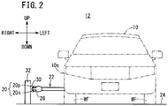
- FIG. 2 shows a schematic overall configuration of the contact type charging system 12 when the electric vehicle 10 is viewed from a front side
- the electric vehicle 10 is a vehicle in which there are mounted an electric motor 14 serving as a drive source, and a driving energy storage device 16 for supplying electrical power to the electric motor 14, and corresponds, for example, to an electric automobile, a hybrid vehicle equipped with an internal combustion engine, and a fuel cell vehicle equipped with a fuel cell.
- the front and rear, left and right, and upper and lower directions will be described in accordance with the directions of the arrows shown in FIGS. 1 and 2 .
- the contact type charging system 12 is constituted at least from power lines 20 made of a conductive material to which electrical power is supplied, and the electric vehicle 10, which is equipped with a charging arm 22 capable of being placed in contact with the power lines 20.
- the charging arm 22 is provided on a side portion 10s on the side of a driver's seat 18 on the right side of the electric vehicle 10, and is disposed between the front wheels WF and the rear wheels WR. In countries in which roads are for right side traveling, the driver's seat 18 generally is located on the left side of the electric vehicle 10, and therefore, the charging arm 22 is disposed on a side portion on the left side of the electric vehicle 10.
- the power lines 20 are arranged along a travel path (road) 24 on which the electric vehicle 10 travels, and are arranged in facing relation to the side portion 10s on the driver's seat 18 side of the electric vehicle 10.
- the power lines 20 are arranged on the side of a central line of the travel path 24.
- the power lines 20 are arranged in the vicinity of the central line and are not disposed respectively in each of the lanes. Further, in the case of a road in which there is a central dividing median, the power lines 20 may be arranged on the median.
- the power lines 20 may be disposed at the length of a specified section.
- the length of the specified section for example, may be set to a length that is capable of charging the electric vehicle 10, so as to be capable of traveling from a position where certain power lines 20 are disposed to the position where next power lines 20 are disposed. While traveling along the power lines 20 on a travel path 24 on which the power lines 20 are arranged, a charging head 26 provided on the distal end of the charging arm 22 of the electric vehicle 10 is extended outwardly in the vehicle transverse direction, and the energy storage device 16 is charged by the charging head 26 coming into contact with the power lines 20.
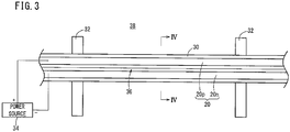
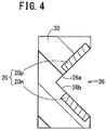
- FIG. 3 is a view showing an installation structure for the power lines 20, and FIG. 4 is a cross-sectional view taken along line IV-IV of FIG. 3 .
- the power lines 20 are retained by a power line retaining unit 30 made of an insulating material, and the power line retaining unit 30 is supported from a rear side thereof by guard posts 32 disposed at predetermined intervals along the travel path 24.
- the guard posts 32 support the power line retaining unit 30 so that the height thereof enables the power lines 20 to come into contact with the distal end of the charging arm 22.
- the power line retaining unit 30 maintains the power lines 20 along the lengthwise direction of the power lines 20.
- a power source 34 supplies electrical power to the power lines 20.
- the power lines 20 include a positive electrode side power line 20p made of a conductive material, and a negative electrode side power line 20n made of a conductive material and arranged below the positive electrode side power line 20p.
- a first voltage which is a high DC voltage
- a second voltage which is a low DC voltage (reference voltage) of a lower direct current than the first voltage, is imposed on the negative electrode side power line 20n from the power source 34.
- a front side of the power line retaining unit 30 is shaped in the form of a V-shaped groove 36 so as to open in the vertical direction.
- the positive electrode side power line 20p is embedded therein so that a front surface thereof is exposed on an upper surface 36a of the V-shaped groove 36
- the negative electrode side power line 20n is embedded therein so that a front surface thereof is exposed on a lower surface 36b of the V-shaped groove 36.
- the voltage imposed on the power lines 20 (20p, 20n) may also be an AC voltage.
- the power lines 20, the power line retaining unit 30, and the power source 34 make up an electrical power supplying device 38 that supplies electrical power to the electric vehicle 10.
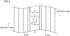
- FIG. 5 is a view showing an example of the electrical power supplying device 38 disposed on a travel path 24.
- a one-side three lane travel path 24, or stated otherwise, a six lane road is illustrated, in which a central median 39 serving as a central line is disposed on the road.
- One of the travel paths 24 is a travel path 24a along which the electric vehicle 10 travels, and the other of the travel paths 24 is a travel path 24b along which an oncoming vehicle travels.
- the central median 39 which serves as a central line, serves to partition the travel path 24a and the travel path 24b.
- power line retaining units 30 that retain the power lines 20 are disposed respectively corresponding to the travel paths 24a, 24b.
- the power line retaining unit 30 that is disposed corresponding to the travel path 24a is disposed on the travel path 24b side of the travel path 24a
- the power line retaining unit 30 that is disposed corresponding to the travel path 24b is disposed on the travel path 24a side of the travel path 24b.
- the power source 34 is disposed between the travel path 24a and the travel path 24b. As shown in FIG. 5 , the power source 34 is disposed on the central median 39. Owing thereto, the power source 34 that supplies power to the power lines 20 disposed on the travel paths 24a, 24b can be used in common.
- a single power source 34 supplies electrical power with respect to the power lines 20 of both of the travel paths 24a, 24b. Consequently, complexity of the electrical wiring from the power source 34 to the power lines 20 of the travel paths 24a, 24b can be suppressed.
- the power line retaining units 30 that retain the power lines 20 of the travel paths 24a, 24b may also be disposed on the central median 39.
- the power line retaining unit 30 corresponding to the travel path 24a is disposed on the side of the travel path 24a
- the power line retaining unit 30 corresponding to the travel path 24b is disposed on the side of the travel path 24b.
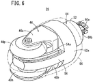
- FIG. 6 is a perspective view of the charging head 26
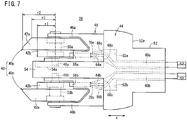
- FIG. 7 is a side view of the charging head 26
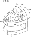
- FIG. 8 is a plan view of the charging head 26.
- the charging head 26 comprises a positive electrode side power receiving element 40p in the form of a roller that contacts the positive electrode side power line 20p of the power lines 20, and a negative electrode side power receiving element 40n in the form of a roller that contacts the negative electrode side power line 20n of the power lines 20.
- the positive electrode side power receiving element 40p and the negative electrode side power receiving element 40n are provided vertically in a pair.
- Power receiving elements 40 (40p, 40n) are disposed on a distal end side of the charging head 26.
- the power receiving elements 40p, 40n are formed from a conductive material. As shown in FIG.
- the power receiving elements 40p, 40n are each of the same structure and shape, and include a first roller member 42a having a substantially frustoconical shape, and a second roller member 42b having a substantially cylindrical shape and disposed on a bottom surface side of the first roller member 42a.
- the first roller member 42a and the second roller member 42b are formed integrally with centers thereof arranged on the same axis (coaxially).
- the cylindrically shaped second roller members 42b have an outer circumferential surface of a first radius r1, and the outer circumferential surface of the first roller members 42a include radii that are larger than the first radius r1. Owing thereto, the first roller members 42a can be placed in contact with respect to the power lines 20, and the circumferential velocity of the outer circumferential surface of the second roller members 42b is smaller in comparison with that of the first roller members 42a. More specifically, the first roller member 42a is substantially in the form of a truncated cone, the bottom surface of which is formed with a circular second radius r2 that is greater than the first radius r1, and the upper surface of which is formed with a circular third radius r3 that is smaller than the second radius r2. Stated otherwise, the outer circumferential surface of the first roller member 42a is formed by the second radius r2 and the third radius r3. The third radius r3 may be either smaller or larger than the first radius r1.
- the power receiving elements 40p, 40n are mounted on the charging head 26 by being separated in a vertically symmetrical manner, such that the second roller members 42b face toward one another mutually. It is possible for the positive electrode side power line 20p and the negative electrode side power line 20n provided in the V-shaped groove 36 to be contacted by the first roller members 42a of the positive electrode side power receiving element 40p and the negative electrode side power receiving element 40n.
- the first roller members 42a may also be formed in a cylindrical columnar shape of the second radius r2. In this case, there is no need for the V-shaped groove 36 to be provided in the power line retaining unit 30.
- the power receiving elements 40p, 40n are axially supported rotatably by a rotary support member 46 that is mounted on a main body portion 44 of the charging head 26.
- the rotary support member 46 includes a first support member 46a that rotatably supports the power receiving element 40p, and a second support member 46b that rotatably supports the power receiving element 40n.
- the first support member 46a includes a support shaft (central shaft) 48a that extends in a vertical direction supporting the power receiving element 40p, and the power receiving element 40p is attached rotatably to the support shaft 48a through a bearing 50a.
- the second support member 46b includes a support shaft (central shaft) 48b that extends in a vertical direction supporting the power receiving element 40n, and the power receiving element 40n is attached rotatably to the support shaft 48b through a bearing 50b.
- the first support member 46a and the second support member 46b have the same shape, and are attached in a vertically symmetrical manner to the main body portion 44.
- wear debris generated by rotation of the power receiving element 40p may fall downwardly and impart an adverse influence on the power receiving element 40n.
- an influence will be effected on the contact state between the power lines 20 and the power receiving element 40n, or that the power receiving element 40p cannot be rotated smoothly, or that an arc may be generated.
- a recessed part 54a is provided, which is recessed a predetermined depth in an upper surface of the partition plate (accommodating section) 54 that is disposed between the power receiving elements 40p, 40n.
- the recessed part 54a is formed around an outer periphery of the partition plate 54. Since wear debris, which is generated by contact friction between the first roller member 42a of the power receiving element 40p and the positive electrode side power line 20p, is accommodated in the recessed part 54a, scattering about of the wear debris that is generated by contact friction between the first roller member 42a of the power receiving element 40p and the positive electrode side power line 20p can be prevented. Accordingly, the occurrence of adverse effects such as insulation defects or the like in peripheral components can be suppressed.
- the recessed part 54a is formed in the partition plate 54 so as to surround the contact position between the power receiving element 40p and the brush 58a. Consequently, since wear debris, which is generated by contact friction between the second roller member 42b of the power receiving element 40p and the brush 58a, is accommodated in the recessed part 54a, scattering about of the wear debris that is generated by contact friction between the second roller member 42b of the power receiving element 40p and the brush 58a can be prevented. Accordingly, the occurrence of adverse effects such as insulation defects or the like in peripheral components can be suppressed.
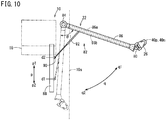
- the charging arm 22 includes, apart from the charging head 26, a bracket 80 to which the charging head 26 is attached, and a slider crank mechanism 82 by which the charging head 26 is moved (rotated) through the bracket 80 in the directions of the arrow q (q1, q2).
- the slider crank mechanism 82 includes the arm portion 86, which is deployed horizontally in a vehicle transverse and outward direction by rotating about a rotary shaft 84 provided on the electric vehicle 10, a slide rail 88, which is mounted along the longitudinal direction of the vehicle body more on an inner side of the vehicle body of the electric vehicle 10 than the arm portion 86, an actuator 90 that slides on the slide rail 88 in the directions of the arrow p (p1, p2), and a spring damper 92, one end of which is attached rotatably to the arm portion 86, and another end of which is attached rotatably to the actuator 90.
- the charging head 26 is attached to the distal end side (a side opposite to the rotary shaft 84) of the arm portion 86 through the bracket 80.
- the spring damper 92 biases the arm portion 86 in a direction to deploy the arm portion 86 outwardly in the vehicle transverse direction.
- the arm portion 86 When the actuator 90 moves on the slide rail 88 in the direction of the arrow p1, the arm portion 86 is rotated about the rotary shaft 84 in the direction of the arrow q1, and the charging head 26 is also moved together therewith in the direction of the arrow q1. As a result, the arm portion 86 opens horizontally about the rotary shaft 84 from a lateral side of the vehicle body of the electric vehicle 10, and the charging head 26 moves to the side of the power lines 20.
- the position of the actuator 90 when the charging head 26 is accommodated (the state shown by the two-dot-dashed lines of FIG. 10 ) is regarded as an initial position d1, and in the case that charging is to be carried out, the actuator 90 is moved from the initial position d1 to a predetermined position d2 along the direction of the arrow p1. Consequently, the arm portion 86 is deployed up to a first angle of rotation ⁇ 1, and the charging head 26 projects (outwardly of the electric vehicle 10) toward the side of the power lines 20 (the state shown by the solid lines of FIG. 10 ).
- the angle of rotation refers to an angle from the state in which the arm portion 86 is accommodated.
- the charging head 26 when the arm portion 86 is deployed up to the first angle of rotation ⁇ 1, the charging head 26 can be placed in contact with the power lines 20, which are separated a first predetermined distance z1 from the side portion 10s on the side of the driver's seat 18 of the electric vehicle 10. Additionally, when the distance to the power lines 20 from the side portion 10s on the side of the driver's seat 18 of the electric vehicle 10 becomes shorter than the first predetermined distance z1, the charging head 26 is pressed by the power lines 20, whereupon the arm portion 86 undergoes rotation in the direction (closing direction) of the arrow q2 in opposition to the biasing force of the spring damper 92. Along therewith, the charging head 26 also is moved in the direction of the arrow q2 (toward the side of the vehicle body).
- the range within which the charging head 26 can be moved in the direction of the arrow q2 is limited.
- the angle of rotation of the arm portion 86 at the time that the spring damper 92 is contracted maximally will be referred to as a second angle of rotation ⁇ 2.
- the arm portion 86 can be rotated within the range of the second angle of rotation ⁇ 2 from the first angle of rotation ⁇ 1.
- the distance between the power lines 20, which are contacted by the power receiving elements 40p, 40n of the charging head 26 when the arm portion 86 is at the second angle of rotation ⁇ 2, and the side portion 10s on the side of the driver's seat 18 of the electric vehicle 10 becomes a second predetermined distance z2 that is shorter than the first predetermined distance z1.
- the angle of rotation of the arm portion 86 does not become smaller than the second angle of rotation ⁇ 2, and therefore, the distance between the power lines 20 and the side portion 10s on the side of the driver's seat 18 of the electric vehicle 10 (also referred to as a "distance between the electric vehicle 10 and the power lines 20) does not become less than the second predetermined distance z2.
- the angle of rotation can be controlled by controlling or interlocking the retraction of the spring damper 92 and movement of the actuator 90.
- the contact pressure between the power lines 20 and the power receiving elements 40p, 40n due to the spring damper 92 can be controlled more finely.
- the rotational range of the arm portion 86 is limited to within a predetermined angular range.
- the contact pressure between the power lines 20 and the power receiving elements 40p, 40n of the charging head 26 can be maintained by the spring damper 92, and thus they can be allowed to contact one another in a stable manner.
- a guideline 100 for guiding the distance between the electric vehicle 10 and the power lines 20 may be disposed on the travel path 24.
- the guideline 100 also constitutes part of the contact type charging system 12.
- the charging head 26 is disposed so that the longitudinal direction of the charging head 26 is perpendicular with respect to the power lines 20 when the rotational angle of the arm portion 86 is at the first angle of rotation ⁇ 1, and the distance between the electric vehicle 10 and the power lines 20 has become the second predetermined distance z2, then the angle ⁇ of the charging head 26 with respect to the power lines 20 becomes excessively small compared to the angles ⁇ 1, ⁇ 2.
- the charging head 26 is disposed so that the longitudinal direction of the charging head 26 is perpendicular with respect to the power lines 20 when the rotational angle of the arm portion 86 is at the second angle of rotation ⁇ 2, and the distance between the electric vehicle 10 and the power lines 20 has become the first predetermined distance z1, then the angle ⁇ of the charging head 26 with respect to the power lines 20 becomes excessively small compared to the angles ⁇ 1, ⁇ 2.
- the charging head 26 by disposing the charging head 26 so that the longitudinal direction of the charging head 26 faces toward the power lines 20 (i.e., so that the charging head 26 and the power lines 20 are disposed face to face) when the rotational angle of the arm portion 86 is at the third angle of rotation ⁇ 3, even if the distance between the electric vehicle 10 and the power lines 20 varies within a range from the first predetermined distance z1 to the second predetermined distance z2, the power receiving elements 40p, 40n of the charging head 26 can stably be placed in contact with the power lines 20.
- the charging head 26 is equipped with the spring members 70a, 70b that press the brushes 58a, 58b toward the side of the power receiving elements 40p, 40n. Owing to this feature, even in the case that the power receiving elements 40p, 40n or the brushes 58a, 58b are abraded and subjected to wear due to contact between the power receiving elements 40p, 40n and the brushes 58a, 58b, the contact state between the power receiving elements 40p, 40n and the brushes 58a, 58b can be maintained by the spring members 70a, 70b.
- the bus bars 60a, 60b that connect the brushes 58a, 58b and the electrical cables 86a, 86b are retained in a slackened state. Owing thereto, the bus bars 60a, 60b can be allowed to follow along with the movement of the brushes 58a, 58b, and thus, the brushes 58a, 58b can be moved toward the side of the power receiving elements 40p, 40n. Consequently, the contact state between the brushes 58a, 58b and the power receiving elements 40p, 40n can be maintained.
- the power receiving elements 40p, 40n are equipped with the first roller members 42a that contact the power lines 20, and the second roller members 42b having the outer circumferential surface of a first radius r1 and which contact the brushes 58a, 58b, and further, the outer circumferential surface of the first roller members 42a include radii that are larger than the first radius r1. Owing thereto, the first roller members 42a can be placed in contact with respect to the power lines 20. Further, the circumferential velocity of the outer circumferential surface of the second roller members 42b is smaller in comparison with that of the first roller members 42a, whereby frictional wear and abrasion between the second roller members 42b and the brushes 58a, 58b can be suppressed.
- the charging arm 22 extends outwardly in the vehicle transverse direction from the side portion 10s on the driver's seat 18 side of the electric vehicle 10, the driver can easily grasp and comprehend the distance between the electric vehicle 10 and the power lines 20, and by steering a non-illustrated steering handle, the contact state between the power lines 20 and the power receiving elements 40p, 40n of the charging arm 22 can suitably be maintained.
- the power source 34 that supplies electrical power to the power lines 20 is disposed between the travel path 24a on which the electric vehicle 10 travels and the travel path 24b on which oncoming vehicles travel, the power source 34 can be used in common with the travel path 24a and the travel path 24b. Consequently, complexity of the electrical wiring from the power source 34 to the power lines 20 of the travel paths 24a, 24b can be suppressed.
- the recessed part 54a which is recessed at a predetermined depth, is formed on the upper surface of the partition plate 54 of the charging head 26, even in the case that the power receiving element 40p or the power line 20 is subjected to frictional wear due to contact between the power receiving element 40p and the power line 20, wear debris therefrom can be accommodated in the recessed part 54a. As a result, the occurrence of adverse effects such as insulation defects or the like in peripheral components by scattering about of such wear debris from the power receiving element 40p or the power line 20 can be suppressed.
- the two bus bars 60aA, 60aA extend from the openings 68aA, 68aA in an upwardly bending manner, and are connected to a brush 58aA through the inside of a first support member 46aA (not shown).
- the two bus bars 60aA, 60aA are retained in a slackened state in the interior of a through hole 64aA of the first support member 46aA (not shown).
- Another recessed part 54aA which is recessed at a predetermined depth around an outer periphery thereof, is formed on the upper surface of the partition plate (accommodating section) 54A.
- Wear debris which is generated by contact friction between a positive electrode side power line 20pA and a power receiving element 40pA, and wear debris, which is generated by contact friction between the power receiving element 40pA and the brush 58aA is accommodated by the recessed part 54aA.
- the communicating state of non-illustrated bus bars 60bA, 60bA is the same as that of the bus bars 60aA, 60aA. More specifically, differently from the above-described embodiment, through holes 62bA are formed horizontally in the interior of the base section 52A, and the cross-sectional areas thereof are of the same size. In addition, a recessed part 110 is formed in a lower surface of the partition plate 54A on the side of openings 68bA, 68bA. The recessed part 110 is formed so that the two bus bars 60bA, 60bA, which extend from the two openings 68bA, 68bA horizontally through the through holes 62bA, will not interfere with the partition plate 54A.
- the two bus bars 60bA, 60bA extend from the openings 68bA, 68bA in an downwardly bending manner, and are connected to a brush 58bA through the inside of a second support member 46bA (not shown). According to the present modification, the two bus bars 60bA, 60bA are retained in a slackened state in the interior of a through hole 64bA of the second support member 46bA (not shown).
- a recess 112 formed in the upper surface of the partition plate 54A is formed for the purpose of receiving a support shaft 48aA therein, and similarly, in the lower surface of the partition plate 54, a recess (not shown) is formed for the purpose of receiving a support shaft 48bA therein.
Landscapes
- Engineering & Computer Science (AREA)
- Mechanical Engineering (AREA)
- Power Engineering (AREA)
- Transportation (AREA)
- Electric Propulsion And Braking For Vehicles (AREA)
- Current-Collector Devices For Electrically Propelled Vehicles (AREA)
- Charge And Discharge Circuits For Batteries Or The Like (AREA)
Applications Claiming Priority (2)
| Application Number | Priority Date | Filing Date | Title |
|---|---|---|---|
| JP2014017508 | 2014-01-31 | ||
| PCT/JP2015/050033 WO2015115122A1 (fr) | 2014-01-31 | 2015-01-05 | Véhicule électrique |
Publications (3)
| Publication Number | Publication Date |
|---|---|
| EP3100897A1 true EP3100897A1 (fr) | 2016-12-07 |
| EP3100897A4 EP3100897A4 (fr) | 2017-08-23 |
| EP3100897B1 EP3100897B1 (fr) | 2019-09-04 |
Family
ID=53756700
Family Applications (1)
| Application Number | Title | Priority Date | Filing Date |
|---|---|---|---|
| EP15742784.0A Active EP3100897B1 (fr) | 2014-01-31 | 2015-01-05 | Véhicule électrique |
Country Status (5)
| Country | Link |
|---|---|
| US (1) | US20170166071A1 (fr) |
| EP (1) | EP3100897B1 (fr) |
| JP (1) | JP6178872B2 (fr) |
| CN (1) | CN105960348B (fr) |
| WO (1) | WO2015115122A1 (fr) |
Cited By (3)
| Publication number | Priority date | Publication date | Assignee | Title |
|---|---|---|---|---|
| WO2019154069A1 (fr) * | 2018-02-06 | 2019-08-15 | 比亚迪股份有限公司 | Dispositif de charge pour véhicule ferroviaire et système de transport ferroviaire |
| CN112008706A (zh) * | 2020-08-31 | 2020-12-01 | 哈尔滨工业大学(深圳) | 一种升降式绳索驱动柔性充电机器人 |
| EP4405204A4 (fr) * | 2021-12-28 | 2025-10-01 | Caterpillar Global Mining Equipment Llc | Système et procédé de support de rails conducteurs surélevés |
Families Citing this family (14)
| Publication number | Priority date | Publication date | Assignee | Title |
|---|---|---|---|---|
| DE102014213831A1 (de) * | 2014-07-16 | 2016-01-21 | Siemens Aktiengesellschaft | Ladevorrichtung für ein elektrisch aufladbares Fahrzeug |
| US11014459B2 (en) | 2015-09-30 | 2021-05-25 | Volvo Truck Corporation | Charging device for a vehicle |
| US10286793B2 (en) * | 2016-02-05 | 2019-05-14 | Faraday & Future Inc. | Autonomous vehicle charging station connection |
| US10071645B2 (en) | 2016-02-05 | 2018-09-11 | Faraday&Future Inc. | Autonomous vehicle charging station connection |
| CN107284276A (zh) * | 2017-07-14 | 2017-10-24 | 尚圣杰 | 一种无限远程续航电动汽车的侧刷充电装置 |
| EA033441B1 (ru) * | 2017-08-03 | 2019-10-31 | Anatoly Eduardovich Yunitsky | Токосъемное устройство путевой структуры транспортной системы |
| CN108928263A (zh) * | 2018-07-12 | 2018-12-04 | 天津益昌电气设备股份有限公司 | 一种毛刷式高速静音电气化铁路输电系统 |
| CN109017374A (zh) * | 2018-07-27 | 2018-12-18 | 南京灵雀智能制造有限公司 | 一种基于公路护栏的连续充电装置 |
| CN108725252A (zh) * | 2018-07-28 | 2018-11-02 | 共享智能铸造产业创新中心有限公司 | 充电支架 |
| US11981221B2 (en) * | 2019-03-20 | 2024-05-14 | Schunk Transit Systems Gmbh | Contact device, vehicle, and charging station |
| DE102020202533A1 (de) * | 2020-02-27 | 2021-09-02 | Siemens Aktiengesellschaft | Ladesystem und Verfahren zum autonomen Laden eines Elektrofahrzeugs |
| CN112918264B (zh) * | 2021-02-01 | 2022-09-27 | 湖南星光速流科技有限责任公司 | 一种受流器 |
| US12377732B2 (en) * | 2021-02-19 | 2025-08-05 | Transportation Ip Holdings, Llc | Electrical shunt apparatus and system |
| RU210271U1 (ru) * | 2021-12-02 | 2022-04-05 | Федеральное государственное бюджетное образовательное учреждение высшего образования "Ульяновский государственный аграрный университет имени П.А. Столыпина" | Токосъёмное устройство |
Family Cites Families (8)
| Publication number | Priority date | Publication date | Assignee | Title |
|---|---|---|---|---|
| JPH02273004A (ja) * | 1989-04-14 | 1990-11-07 | Mitsubishi Agricult Mach Co Ltd | 作業用走行車の架線式自動操行装置 |
| CN1262191A (zh) * | 2000-02-02 | 2000-08-09 | 徐正义 | 双弓四单元多回路电车集电系统 |
| CN201380759Y (zh) * | 2009-04-19 | 2010-01-13 | 李学军 | 电机车集电弓 |
| CN102354889A (zh) * | 2011-09-20 | 2012-02-15 | 江苏江鹤滑线电气有限公司 | 一种滑触式运动导电装置 |
| CN202206014U (zh) * | 2011-09-20 | 2012-04-25 | 江苏江鹤滑线电气有限公司 | 轮式集电器 |
| JP6138425B2 (ja) * | 2012-04-27 | 2017-05-31 | 本田技研工業株式会社 | 電動車両の接触充電方法及び接触充電システム |
| WO2013179740A1 (fr) * | 2012-05-31 | 2013-12-05 | 株式会社日立エンジニアリング・アンド・サービス | Dispositif à pantographe de camion à trolley |
| WO2013179749A1 (fr) * | 2012-05-31 | 2013-12-05 | エドワーズ株式会社 | Moteur à aimants permanents internes destiné à une pompe à vide |
-
2015
- 2015-01-05 CN CN201580006306.0A patent/CN105960348B/zh active Active
- 2015-01-05 US US15/115,560 patent/US20170166071A1/en not_active Abandoned
- 2015-01-05 WO PCT/JP2015/050033 patent/WO2015115122A1/fr not_active Ceased
- 2015-01-05 EP EP15742784.0A patent/EP3100897B1/fr active Active
- 2015-01-05 JP JP2015559837A patent/JP6178872B2/ja active Active
Cited By (5)
| Publication number | Priority date | Publication date | Assignee | Title |
|---|---|---|---|---|
| WO2019154069A1 (fr) * | 2018-02-06 | 2019-08-15 | 比亚迪股份有限公司 | Dispositif de charge pour véhicule ferroviaire et système de transport ferroviaire |
| CN112008706A (zh) * | 2020-08-31 | 2020-12-01 | 哈尔滨工业大学(深圳) | 一种升降式绳索驱动柔性充电机器人 |
| CN112008706B (zh) * | 2020-08-31 | 2022-02-11 | 哈尔滨工业大学(深圳) | 一种升降式绳索驱动柔性充电机器人 |
| EP4405204A4 (fr) * | 2021-12-28 | 2025-10-01 | Caterpillar Global Mining Equipment Llc | Système et procédé de support de rails conducteurs surélevés |
| US12583364B2 (en) | 2021-12-28 | 2026-03-24 | Caterpillar Global Mining Equipment Llc | System and method for supporting elevated power rails |
Also Published As
| Publication number | Publication date |
|---|---|
| EP3100897A4 (fr) | 2017-08-23 |
| EP3100897B1 (fr) | 2019-09-04 |
| JP6178872B2 (ja) | 2017-08-09 |
| US20170166071A1 (en) | 2017-06-15 |
| CN105960348A (zh) | 2016-09-21 |
| CN105960348B (zh) | 2018-03-06 |
| WO2015115122A1 (fr) | 2015-08-06 |
| JPWO2015115122A1 (ja) | 2017-03-23 |
Similar Documents
| Publication | Publication Date | Title |
|---|---|---|
| EP3100897B1 (fr) | Véhicule électrique | |
| EP3427997B1 (fr) | Appareil de charge de contact avec bras de charge et système de charge de contact pour véhicule électrique | |
| WO2015115474A1 (fr) | Véhicule électrique, système de charge par contact et dispositif d'alimentation électrique | |
| JP6138425B2 (ja) | 電動車両の接触充電方法及び接触充電システム | |
| JP2013233037A5 (fr) | ||
| JP6163115B2 (ja) | 電動車両 | |
| JP6460068B2 (ja) | 車両 | |
| JP5759575B2 (ja) | 電動車両及び電動車両の接触充電システム | |
| US20170166084A1 (en) | Power feeding device and contact power feeding system | |
| JP6170448B2 (ja) | 電動車両 | |
| US10566597B2 (en) | Battery wiring module | |
| JP5883464B2 (ja) | 乗用電動車両及び乗用電動車両の接触充電システム | |
| WO2012074095A1 (fr) | Système d'alimentation électrique pour véhicule électrique | |
| KR101380703B1 (ko) | 집전 장치 | |
| JP5759576B2 (ja) | 電動車両及び電動車両の接触充電システム | |
| HK1181009B (en) | Guide rail for track-based vehicle, and traffic system |
Legal Events
| Date | Code | Title | Description |
|---|---|---|---|
| PUAI | Public reference made under article 153(3) epc to a published international application that has entered the european phase |
Free format text: ORIGINAL CODE: 0009012 |
|
| STAA | Information on the status of an ep patent application or granted ep patent |
Free format text: STATUS: REQUEST FOR EXAMINATION WAS MADE |
|
| 17P | Request for examination filed |
Effective date: 20160729 |
|
| AK | Designated contracting states |
Kind code of ref document: A1 Designated state(s): AL AT BE BG CH CY CZ DE DK EE ES FI FR GB GR HR HU IE IS IT LI LT LU LV MC MK MT NL NO PL PT RO RS SE SI SK SM TR |
|
| AX | Request for extension of the european patent |
Extension state: BA ME |
|
| DAX | Request for extension of the european patent (deleted) | ||
| A4 | Supplementary search report drawn up and despatched |
Effective date: 20170726 |
|
| RIC1 | Information provided on ipc code assigned before grant |
Ipc: B60L 11/18 20060101ALI20170720BHEP Ipc: B60L 5/40 20060101ALI20170720BHEP Ipc: B60M 7/00 20060101ALI20170720BHEP Ipc: B60L 5/38 20060101AFI20170720BHEP |
|
| RIC1 | Information provided on ipc code assigned before grant |
Ipc: B60L 5/40 20060101ALI20190201BHEP Ipc: B60M 7/00 20060101ALI20190201BHEP Ipc: B60L 5/38 20060101AFI20190201BHEP |
|
| GRAP | Despatch of communication of intention to grant a patent |
Free format text: ORIGINAL CODE: EPIDOSNIGR1 |
|
| STAA | Information on the status of an ep patent application or granted ep patent |
Free format text: STATUS: GRANT OF PATENT IS INTENDED |
|
| INTG | Intention to grant announced |
Effective date: 20190321 |
|
| GRAS | Grant fee paid |
Free format text: ORIGINAL CODE: EPIDOSNIGR3 |
|
| GRAA | (expected) grant |
Free format text: ORIGINAL CODE: 0009210 |
|
| STAA | Information on the status of an ep patent application or granted ep patent |
Free format text: STATUS: THE PATENT HAS BEEN GRANTED |
|
| AK | Designated contracting states |
Kind code of ref document: B1 Designated state(s): AL AT BE BG CH CY CZ DE DK EE ES FI FR GB GR HR HU IE IS IT LI LT LU LV MC MK MT NL NO PL PT RO RS SE SI SK SM TR |
|
| REG | Reference to a national code |
Ref country code: GB Ref legal event code: FG4D |
|
| REG | Reference to a national code |
Ref country code: CH Ref legal event code: EP |
|
| REG | Reference to a national code |
Ref country code: AT Ref legal event code: REF Ref document number: 1174878 Country of ref document: AT Kind code of ref document: T Effective date: 20190915 |
|
| REG | Reference to a national code |
Ref country code: DE Ref legal event code: R096 Ref document number: 602015037187 Country of ref document: DE |
|
| REG | Reference to a national code |
Ref country code: IE Ref legal event code: FG4D |
|
| REG | Reference to a national code |
Ref country code: NL Ref legal event code: MP Effective date: 20190904 |
|
| REG | Reference to a national code |
Ref country code: LT Ref legal event code: MG4D |
|
| PG25 | Lapsed in a contracting state [announced via postgrant information from national office to epo] |
Ref country code: FI Free format text: LAPSE BECAUSE OF FAILURE TO SUBMIT A TRANSLATION OF THE DESCRIPTION OR TO PAY THE FEE WITHIN THE PRESCRIBED TIME-LIMIT Effective date: 20190904 Ref country code: NO Free format text: LAPSE BECAUSE OF FAILURE TO SUBMIT A TRANSLATION OF THE DESCRIPTION OR TO PAY THE FEE WITHIN THE PRESCRIBED TIME-LIMIT Effective date: 20191204 Ref country code: SE Free format text: LAPSE BECAUSE OF FAILURE TO SUBMIT A TRANSLATION OF THE DESCRIPTION OR TO PAY THE FEE WITHIN THE PRESCRIBED TIME-LIMIT Effective date: 20190904 Ref country code: BG Free format text: LAPSE BECAUSE OF FAILURE TO SUBMIT A TRANSLATION OF THE DESCRIPTION OR TO PAY THE FEE WITHIN THE PRESCRIBED TIME-LIMIT Effective date: 20191204 Ref country code: LT Free format text: LAPSE BECAUSE OF FAILURE TO SUBMIT A TRANSLATION OF THE DESCRIPTION OR TO PAY THE FEE WITHIN THE PRESCRIBED TIME-LIMIT Effective date: 20190904 Ref country code: HR Free format text: LAPSE BECAUSE OF FAILURE TO SUBMIT A TRANSLATION OF THE DESCRIPTION OR TO PAY THE FEE WITHIN THE PRESCRIBED TIME-LIMIT Effective date: 20190904 |
|
| PG25 | Lapsed in a contracting state [announced via postgrant information from national office to epo] |
Ref country code: GR Free format text: LAPSE BECAUSE OF FAILURE TO SUBMIT A TRANSLATION OF THE DESCRIPTION OR TO PAY THE FEE WITHIN THE PRESCRIBED TIME-LIMIT Effective date: 20191205 Ref country code: AL Free format text: LAPSE BECAUSE OF FAILURE TO SUBMIT A TRANSLATION OF THE DESCRIPTION OR TO PAY THE FEE WITHIN THE PRESCRIBED TIME-LIMIT Effective date: 20190904 Ref country code: ES Free format text: LAPSE BECAUSE OF FAILURE TO SUBMIT A TRANSLATION OF THE DESCRIPTION OR TO PAY THE FEE WITHIN THE PRESCRIBED TIME-LIMIT Effective date: 20190904 Ref country code: LV Free format text: LAPSE BECAUSE OF FAILURE TO SUBMIT A TRANSLATION OF THE DESCRIPTION OR TO PAY THE FEE WITHIN THE PRESCRIBED TIME-LIMIT Effective date: 20190904 Ref country code: RS Free format text: LAPSE BECAUSE OF FAILURE TO SUBMIT A TRANSLATION OF THE DESCRIPTION OR TO PAY THE FEE WITHIN THE PRESCRIBED TIME-LIMIT Effective date: 20190904 |
|
| REG | Reference to a national code |
Ref country code: AT Ref legal event code: MK05 Ref document number: 1174878 Country of ref document: AT Kind code of ref document: T Effective date: 20190904 |
|
| PG25 | Lapsed in a contracting state [announced via postgrant information from national office to epo] |
Ref country code: RO Free format text: LAPSE BECAUSE OF FAILURE TO SUBMIT A TRANSLATION OF THE DESCRIPTION OR TO PAY THE FEE WITHIN THE PRESCRIBED TIME-LIMIT Effective date: 20190904 Ref country code: IT Free format text: LAPSE BECAUSE OF FAILURE TO SUBMIT A TRANSLATION OF THE DESCRIPTION OR TO PAY THE FEE WITHIN THE PRESCRIBED TIME-LIMIT Effective date: 20190904 Ref country code: NL Free format text: LAPSE BECAUSE OF FAILURE TO SUBMIT A TRANSLATION OF THE DESCRIPTION OR TO PAY THE FEE WITHIN THE PRESCRIBED TIME-LIMIT Effective date: 20190904 Ref country code: EE Free format text: LAPSE BECAUSE OF FAILURE TO SUBMIT A TRANSLATION OF THE DESCRIPTION OR TO PAY THE FEE WITHIN THE PRESCRIBED TIME-LIMIT Effective date: 20190904 Ref country code: PT Free format text: LAPSE BECAUSE OF FAILURE TO SUBMIT A TRANSLATION OF THE DESCRIPTION OR TO PAY THE FEE WITHIN THE PRESCRIBED TIME-LIMIT Effective date: 20200106 Ref country code: PL Free format text: LAPSE BECAUSE OF FAILURE TO SUBMIT A TRANSLATION OF THE DESCRIPTION OR TO PAY THE FEE WITHIN THE PRESCRIBED TIME-LIMIT Effective date: 20190904 Ref country code: AT Free format text: LAPSE BECAUSE OF FAILURE TO SUBMIT A TRANSLATION OF THE DESCRIPTION OR TO PAY THE FEE WITHIN THE PRESCRIBED TIME-LIMIT Effective date: 20190904 |
|
| PGFP | Annual fee paid to national office [announced via postgrant information from national office to epo] |
Ref country code: DE Payment date: 20200130 Year of fee payment: 6 |
|
| PG25 | Lapsed in a contracting state [announced via postgrant information from national office to epo] |
Ref country code: CZ Free format text: LAPSE BECAUSE OF FAILURE TO SUBMIT A TRANSLATION OF THE DESCRIPTION OR TO PAY THE FEE WITHIN THE PRESCRIBED TIME-LIMIT Effective date: 20190904 Ref country code: SK Free format text: LAPSE BECAUSE OF FAILURE TO SUBMIT A TRANSLATION OF THE DESCRIPTION OR TO PAY THE FEE WITHIN THE PRESCRIBED TIME-LIMIT Effective date: 20190904 Ref country code: IS Free format text: LAPSE BECAUSE OF FAILURE TO SUBMIT A TRANSLATION OF THE DESCRIPTION OR TO PAY THE FEE WITHIN THE PRESCRIBED TIME-LIMIT Effective date: 20200224 Ref country code: SM Free format text: LAPSE BECAUSE OF FAILURE TO SUBMIT A TRANSLATION OF THE DESCRIPTION OR TO PAY THE FEE WITHIN THE PRESCRIBED TIME-LIMIT Effective date: 20190904 |
|
| REG | Reference to a national code |
Ref country code: DE Ref legal event code: R097 Ref document number: 602015037187 Country of ref document: DE |
|
| PGFP | Annual fee paid to national office [announced via postgrant information from national office to epo] |
Ref country code: FR Payment date: 20200123 Year of fee payment: 6 |
|
| PLBE | No opposition filed within time limit |
Free format text: ORIGINAL CODE: 0009261 |
|
| STAA | Information on the status of an ep patent application or granted ep patent |
Free format text: STATUS: NO OPPOSITION FILED WITHIN TIME LIMIT |
|
| PG2D | Information on lapse in contracting state deleted |
Ref country code: IS |
|
| PG25 | Lapsed in a contracting state [announced via postgrant information from national office to epo] |
Ref country code: IS Free format text: LAPSE BECAUSE OF FAILURE TO SUBMIT A TRANSLATION OF THE DESCRIPTION OR TO PAY THE FEE WITHIN THE PRESCRIBED TIME-LIMIT Effective date: 20200105 Ref country code: DK Free format text: LAPSE BECAUSE OF FAILURE TO SUBMIT A TRANSLATION OF THE DESCRIPTION OR TO PAY THE FEE WITHIN THE PRESCRIBED TIME-LIMIT Effective date: 20190904 |
|
| 26N | No opposition filed |
Effective date: 20200605 |
|
| PG25 | Lapsed in a contracting state [announced via postgrant information from national office to epo] |
Ref country code: MC Free format text: LAPSE BECAUSE OF FAILURE TO SUBMIT A TRANSLATION OF THE DESCRIPTION OR TO PAY THE FEE WITHIN THE PRESCRIBED TIME-LIMIT Effective date: 20190904 Ref country code: SI Free format text: LAPSE BECAUSE OF FAILURE TO SUBMIT A TRANSLATION OF THE DESCRIPTION OR TO PAY THE FEE WITHIN THE PRESCRIBED TIME-LIMIT Effective date: 20190904 |
|
| REG | Reference to a national code |
Ref country code: CH Ref legal event code: PL |
|
| GBPC | Gb: european patent ceased through non-payment of renewal fee |
Effective date: 20200105 |
|
| REG | Reference to a national code |
Ref country code: BE Ref legal event code: MM Effective date: 20200131 |
|
| PG25 | Lapsed in a contracting state [announced via postgrant information from national office to epo] |
Ref country code: LU Free format text: LAPSE BECAUSE OF NON-PAYMENT OF DUE FEES Effective date: 20200105 Ref country code: GB Free format text: LAPSE BECAUSE OF NON-PAYMENT OF DUE FEES Effective date: 20200105 |
|
| PG25 | Lapsed in a contracting state [announced via postgrant information from national office to epo] |
Ref country code: BE Free format text: LAPSE BECAUSE OF NON-PAYMENT OF DUE FEES Effective date: 20200131 Ref country code: CH Free format text: LAPSE BECAUSE OF NON-PAYMENT OF DUE FEES Effective date: 20200131 Ref country code: LI Free format text: LAPSE BECAUSE OF NON-PAYMENT OF DUE FEES Effective date: 20200131 |
|
| PG25 | Lapsed in a contracting state [announced via postgrant information from national office to epo] |
Ref country code: IE Free format text: LAPSE BECAUSE OF NON-PAYMENT OF DUE FEES Effective date: 20200105 |
|
| REG | Reference to a national code |
Ref country code: DE Ref legal event code: R119 Ref document number: 602015037187 Country of ref document: DE |
|
| PG25 | Lapsed in a contracting state [announced via postgrant information from national office to epo] |
Ref country code: FR Free format text: LAPSE BECAUSE OF NON-PAYMENT OF DUE FEES Effective date: 20210131 |
|
| PG25 | Lapsed in a contracting state [announced via postgrant information from national office to epo] |
Ref country code: DE Free format text: LAPSE BECAUSE OF NON-PAYMENT OF DUE FEES Effective date: 20210803 |
|
| PG25 | Lapsed in a contracting state [announced via postgrant information from national office to epo] |
Ref country code: TR Free format text: LAPSE BECAUSE OF FAILURE TO SUBMIT A TRANSLATION OF THE DESCRIPTION OR TO PAY THE FEE WITHIN THE PRESCRIBED TIME-LIMIT Effective date: 20190904 Ref country code: MT Free format text: LAPSE BECAUSE OF FAILURE TO SUBMIT A TRANSLATION OF THE DESCRIPTION OR TO PAY THE FEE WITHIN THE PRESCRIBED TIME-LIMIT Effective date: 20190904 Ref country code: CY Free format text: LAPSE BECAUSE OF FAILURE TO SUBMIT A TRANSLATION OF THE DESCRIPTION OR TO PAY THE FEE WITHIN THE PRESCRIBED TIME-LIMIT Effective date: 20190904 |
|
| PG25 | Lapsed in a contracting state [announced via postgrant information from national office to epo] |
Ref country code: MK Free format text: LAPSE BECAUSE OF FAILURE TO SUBMIT A TRANSLATION OF THE DESCRIPTION OR TO PAY THE FEE WITHIN THE PRESCRIBED TIME-LIMIT Effective date: 20190904 |