EP3100908A1 - Scheinwerfersteuerungsvorrichtung und scheinwerfer - Google Patents
Scheinwerfersteuerungsvorrichtung und scheinwerfer Download PDFInfo
- Publication number
- EP3100908A1 EP3100908A1 EP15743713.8A EP15743713A EP3100908A1 EP 3100908 A1 EP3100908 A1 EP 3100908A1 EP 15743713 A EP15743713 A EP 15743713A EP 3100908 A1 EP3100908 A1 EP 3100908A1
- Authority
- EP
- European Patent Office
- Prior art keywords
- headlight
- light source
- light
- controller
- irradiated
- Prior art date
- Legal status (The legal status is an assumption and is not a legal conclusion. Google has not performed a legal analysis and makes no representation as to the accuracy of the status listed.)
- Withdrawn
Links
Images




Classifications
-
- H—ELECTRICITY
- H05—ELECTRIC TECHNIQUES NOT OTHERWISE PROVIDED FOR
- H05B—ELECTRIC HEATING; ELECTRIC LIGHT SOURCES NOT OTHERWISE PROVIDED FOR; CIRCUIT ARRANGEMENTS FOR ELECTRIC LIGHT SOURCES, IN GENERAL
- H05B47/00—Circuit arrangements for operating light sources in general, i.e. where the type of light source is not relevant
- H05B47/10—Controlling the light source
- H05B47/105—Controlling the light source in response to determined parameters
- H05B47/115—Controlling the light source in response to determined parameters by determining the presence or movement of objects or living beings
-
- B—PERFORMING OPERATIONS; TRANSPORTING
- B60—VEHICLES IN GENERAL
- B60Q—ARRANGEMENT OF SIGNALLING OR LIGHTING DEVICES, THE MOUNTING OR SUPPORTING THEREOF OR CIRCUITS THEREFOR, FOR VEHICLES IN GENERAL
- B60Q1/00—Arrangement of optical signalling or lighting devices, the mounting or supporting thereof or circuits therefor
- B60Q1/02—Arrangement of optical signalling or lighting devices, the mounting or supporting thereof or circuits therefor the devices being primarily intended to illuminate the way ahead or to illuminate other areas of way or environments
- B60Q1/04—Arrangement of optical signalling or lighting devices, the mounting or supporting thereof or circuits therefor the devices being primarily intended to illuminate the way ahead or to illuminate other areas of way or environments the devices being headlights
- B60Q1/06—Arrangement of optical signalling or lighting devices, the mounting or supporting thereof or circuits therefor the devices being primarily intended to illuminate the way ahead or to illuminate other areas of way or environments the devices being headlights adjustable, e.g. remotely-controlled from inside vehicle
- B60Q1/08—Arrangement of optical signalling or lighting devices, the mounting or supporting thereof or circuits therefor the devices being primarily intended to illuminate the way ahead or to illuminate other areas of way or environments the devices being headlights adjustable, e.g. remotely-controlled from inside vehicle automatically
- B60Q1/085—Arrangement of optical signalling or lighting devices, the mounting or supporting thereof or circuits therefor the devices being primarily intended to illuminate the way ahead or to illuminate other areas of way or environments the devices being headlights adjustable, e.g. remotely-controlled from inside vehicle automatically due to special conditions, e.g. adverse weather, type of road, badly illuminated road signs or potential dangers
-
- B—PERFORMING OPERATIONS; TRANSPORTING
- B60—VEHICLES IN GENERAL
- B60Q—ARRANGEMENT OF SIGNALLING OR LIGHTING DEVICES, THE MOUNTING OR SUPPORTING THEREOF OR CIRCUITS THEREFOR, FOR VEHICLES IN GENERAL
- B60Q1/00—Arrangement of optical signalling or lighting devices, the mounting or supporting thereof or circuits therefor
- B60Q1/02—Arrangement of optical signalling or lighting devices, the mounting or supporting thereof or circuits therefor the devices being primarily intended to illuminate the way ahead or to illuminate other areas of way or environments
- B60Q1/04—Arrangement of optical signalling or lighting devices, the mounting or supporting thereof or circuits therefor the devices being primarily intended to illuminate the way ahead or to illuminate other areas of way or environments the devices being headlights
- B60Q1/14—Arrangement of optical signalling or lighting devices, the mounting or supporting thereof or circuits therefor the devices being primarily intended to illuminate the way ahead or to illuminate other areas of way or environments the devices being headlights having dimming means
- B60Q1/1415—Dimming circuits
- B60Q1/1423—Automatic dimming circuits, i.e. switching between high beam and low beam due to change of ambient light or light level in road traffic
- B60Q1/143—Automatic dimming circuits, i.e. switching between high beam and low beam due to change of ambient light or light level in road traffic combined with another condition, e.g. using vehicle recognition from camera images or activation of wipers
-
- F—MECHANICAL ENGINEERING; LIGHTING; HEATING; WEAPONS; BLASTING
- F21—LIGHTING
- F21S—NON-PORTABLE LIGHTING DEVICES; SYSTEMS THEREOF; VEHICLE LIGHTING DEVICES SPECIALLY ADAPTED FOR VEHICLE EXTERIORS
- F21S41/00—Illuminating devices specially adapted for vehicle exteriors, e.g. headlamps
- F21S41/30—Illuminating devices specially adapted for vehicle exteriors, e.g. headlamps characterised by reflectors
- F21S41/32—Optical layout thereof
- F21S41/36—Combinations of two or more separate reflectors
-
- B—PERFORMING OPERATIONS; TRANSPORTING
- B60—VEHICLES IN GENERAL
- B60Q—ARRANGEMENT OF SIGNALLING OR LIGHTING DEVICES, THE MOUNTING OR SUPPORTING THEREOF OR CIRCUITS THEREFOR, FOR VEHICLES IN GENERAL
- B60Q2200/00—Special features or arrangements of vehicle headlamps
-
- B—PERFORMING OPERATIONS; TRANSPORTING
- B60—VEHICLES IN GENERAL
- B60Q—ARRANGEMENT OF SIGNALLING OR LIGHTING DEVICES, THE MOUNTING OR SUPPORTING THEREOF OR CIRCUITS THEREFOR, FOR VEHICLES IN GENERAL
- B60Q2300/00—Indexing codes for automatically adjustable headlamps or automatically dimmable headlamps
- B60Q2300/05—Special features for controlling or switching of the light beam
- B60Q2300/054—Variable non-standard intensity, i.e. emission of various beam intensities different from standard intensities, e.g. continuous or stepped transitions of intensity
-
- B—PERFORMING OPERATIONS; TRANSPORTING
- B60—VEHICLES IN GENERAL
- B60Q—ARRANGEMENT OF SIGNALLING OR LIGHTING DEVICES, THE MOUNTING OR SUPPORTING THEREOF OR CIRCUITS THEREFOR, FOR VEHICLES IN GENERAL
- B60Q2300/00—Indexing codes for automatically adjustable headlamps or automatically dimmable headlamps
- B60Q2300/40—Indexing codes relating to other road users or special conditions
- B60Q2300/45—Special conditions, e.g. pedestrians, road signs or potential dangers
-
- F—MECHANICAL ENGINEERING; LIGHTING; HEATING; WEAPONS; BLASTING
- F21—LIGHTING
- F21Y—INDEXING SCHEME ASSOCIATED WITH SUBCLASSES F21K, F21L, F21S and F21V, RELATING TO THE FORM OR THE KIND OF THE LIGHT SOURCES OR OF THE COLOUR OF THE LIGHT EMITTED
- F21Y2115/00—Light-generating elements of semiconductor light sources
- F21Y2115/10—Light-emitting diodes [LED]
-
- H—ELECTRICITY
- H05—ELECTRIC TECHNIQUES NOT OTHERWISE PROVIDED FOR
- H05B—ELECTRIC HEATING; ELECTRIC LIGHT SOURCES NOT OTHERWISE PROVIDED FOR; CIRCUIT ARRANGEMENTS FOR ELECTRIC LIGHT SOURCES, IN GENERAL
- H05B47/00—Circuit arrangements for operating light sources in general, i.e. where the type of light source is not relevant
- H05B47/10—Controlling the light source
- H05B47/105—Controlling the light source in response to determined parameters
- H05B47/115—Controlling the light source in response to determined parameters by determining the presence or movement of objects or living beings
- H05B47/125—Controlling the light source in response to determined parameters by determining the presence or movement of objects or living beings by using cameras
-
- Y—GENERAL TAGGING OF NEW TECHNOLOGICAL DEVELOPMENTS; GENERAL TAGGING OF CROSS-SECTIONAL TECHNOLOGIES SPANNING OVER SEVERAL SECTIONS OF THE IPC; TECHNICAL SUBJECTS COVERED BY FORMER USPC CROSS-REFERENCE ART COLLECTIONS [XRACs] AND DIGESTS
- Y02—TECHNOLOGIES OR APPLICATIONS FOR MITIGATION OR ADAPTATION AGAINST CLIMATE CHANGE
- Y02B—CLIMATE CHANGE MITIGATION TECHNOLOGIES RELATED TO BUILDINGS, e.g. HOUSING, HOUSE APPLIANCES OR RELATED END-USER APPLICATIONS
- Y02B20/00—Energy efficient lighting technologies, e.g. halogen lamps or gas discharge lamps
- Y02B20/40—Control techniques providing energy savings, e.g. smart controller or presence detection
Definitions
- the present disclosure relates to a headlight control device and a headlight.
- the multilight-type headlight aims at suppressing the dazzle of a pedestrian and, at the same time, aims at enabling a driver to make the visual confirmation of a pedestrian satisfactorily.
- the multilight-type headlight includes a pedestrian light specifying unit and an illumination amount controller. Based on position information of a pedestrian acquired from a pedestrian detection sensor, the pedestrian light specifying unit specifies the light to illuminate the pedestrian.
- the illumination amount controller reduces the illumination amount to the upper half of the body of the pedestrian irradiated by the light specified by the pedestrian light specifying unit, as the distance to the pedestrian acquired from the pedestrian detection sensor becomes smaller.
- the multilight-type headlight flashes a pedestrian photographing area, when there is a possibility that distance may approach within a threshold.
- Patent Literature 1 JP-2013-184614A
- the inventors of the present application have found out the following issues regarding the headlight control device and the headlight.
- the above-described multilight-type headlight flashes a pedestrian by use of a spotlight, in order to notify a driver of the presence of the pedestrian at night.
- the multilight-type headlight changes periodically the angle of a pedestrian illumination mirror, from the inside of a pedestrian photographing area to the outside of the pedestrian photographing area and from the outside of the pedestrian photographing area to the inside of the pedestrian photographing area.
- the multilight-type headlight flashes the pedestrian by use of a spotlight in this way.
- the angle of the pedestrian illumination mirror is changed to the outside of the pedestrian photographing area, no light is momentarily irradiated to the pedestrian.
- the object which the driver should confirm visually includes other obstacles than pedestrians, such as parking vehicles.
- the present disclosure is made in view of the above and has an object to provide a headlight control device and a headlight that can irradiate the light to an obstacle so as to be easily confirmed visually by a driver and at the same time can suppress a situation of no light being momentarily irradiated to the obstacle.
- a headlight control device it is possible to irradiate the light to an obstacle so as to be easily confirmed visually by a driver, by setting the area including the obstacle as the intensified illumination area to which the light from the light source is irradiated in a mode different from the peripheral area of the area. Furthermore, it is possible to suppress the situation of no light being momentarily irradiated to the obstacle, by controlling the distribution of the light irradiated from a light source so as to include an illuminated zone and a non-illuminated zone in this intensified illumination area.
- a headlight 10 includes a headlight controller 11, a light source 12, a digital mirror 13, and a front detector 14.
- the headlight 10 is mounted to a front part of a vehicle and illuminates a forward direction of the vehicle when the vehicle runs at night or the like.
- the headlight 10 is also called a headlamp.
- the headlight controller 11 corresponds to a headlight control device.
- the headlight controller 11 is an electronic control unit which includes a processing unit, a storage unit, and an input/output unit, for example.
- the headlight controller 11 controls the headlight 10 and controls a distribution of light irradiated from the light source 12.
- the headlight controller 11 is electrically coupled to the light source 12, the digital mirror 13, and the front detector 14.
- the headlight controller 11 acquires a detection result from the front detector and outputs a control signal to the light source 12 and the digital mirror 13. A processing operation of the headlight controller 11 will be explained in detail later.
- the light source 12 is based on a well-known technology, and can employ a light emitting diode (hereinafter described as an LED), a halogen lamp, a metal halide lamp, etc.
- the light source 12 includes at least one light source for a high beam and at least one light source for a low beam.
- the high beam is upward and is irradiated to a long distance.
- the high beam is horizontally irradiated, and is irradiated to a longer distance than the low beam. Therefore, the high beam can be rephrased as a travelling headlight.
- the low beam is downward and is irradiated to a near distance than the high beam. Therefore, the low beam can be rephrased as a crossing headlight.
- the light source 12 is not limited to this. It suffices that the headlight 10 may include at least one light source 12.
- FIG. 4 is a conceptual drawing illustrating the front of the vehicle when the light source 12 irradiates only the low beam.
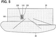
- FIG. 5 is a conceptual drawing illustrating the front of the vehicle when the light source 12 irradiates the low beam and the high beam.
- the symbol 20 in FIGS. 4 and 5 illustrates a high beam area which the light source 12 can irradiate with the high beam
- the symbol 30 illustrates a low beam area which the light source 12 can irradiate with the low beam. Therefore, the available illumination area of the headlight 10 is given by the high beam area 20 and the low beam area 30.
- the area irradiated with the light from the light source 12 is hatched (although not a sectional view), in order to clarify the area irradiated with the light from the light source 12 and the area not irradiated. Furthermore, in the present embodiment, in other drawings such as FIG. 3 in addition to FIGS. 4 and 5 , the area irradiated with the light from the light source 12 is hatched.
- the digital mirror 13 is an array of multiple mirrors 131.
- This digital mirror 13 can be called an MEMS mirror.
- the mirror 131 can be called a micro mirror.
- the MEMS stands for a Micro Electro Mechanical System.
- the mirror 131 can also be called a mirror element and a single mirror body.
- the digital mirror 13 provided with 153 mirrors 131 (9 by 17 pieces) is adopted as an example. That is, the digital mirror 13 is provided with 153 mirrors 131 which are arranged from y1 to y9 vertically and from x1 to x17 horizontally. However, the digital mirror 13 may employ mirrors 131 more than 153 pieces, or mirrors 131 less than 153 pieces.
- Each of the mirrors 131 is configured to switchover between an ON state and an OFF state in response to a control signal from the headlight controller 11.
- Each mirror 131 is configured to reflect the light from the light source 12 and to irradiate the reflected light toward the front of the vehicle, when the mirror is set to the ON state.
- Each mirror 131 is configured not to irradiate the light, which is irradiated from the light source 12, toward the front of the vehicle, when the mirror is set to the OFF state. That is, the headlight controller 11 sets each of the mirrors 131 to the ON state or the OFF state separately, to control the distribution of the light irradiated from the light source 12.
- each mirror 131 changes an angle thereof depending on the ON state or the OFF state.
- a mirror 131 in the ON state is set to an angle which reflects the light, which is irradiated from the light source 12, toward the front of the vehicle.
- a mirror 131 in the OFF state is set to an angle which does not reflect the light, which is irradiated from the light source 12, toward the front of the vehicle. Therefore, the headlight controller 11 performs control of switching between the ON state and the OFF state of each mirror 131, by outputting to the digital mirror 13 a control signal which instructs the angle of each mirror 131.
- the digital mirror 13 refers to a DMD (Digital Micromirror Device) disclosed in Patent Literature 1, for example.
- the present embodiment adopts an example employing the digital mirror 13 to control the distribution of the light irradiated from the light source 12 by the ON state and the OFF state of the mirror 131 in the digital mirror 13.
- the embodiment is not limited to this example.
- the front detector 14 is a device which detects an obstacle existing in front of the vehicle and the position of the obstacle.
- the front detector 14 can employ a camera and an infrared sensor which are well known, for example.
- the front detector 14 detects the presence or absence of an obstacle and the position of the obstacle, by pattern matching using a picture photographed by the camera and a template, and notifies the detection result to the headlight controller 11.
- any of the headlight controller 11 and the front detector 14 can associate the position of the obstacle detected by the front detector 14 with the position of each mirror 131.
- any the headlight controller 11 and the front detector 14 can associate the position of the obstacle detected by the front detector 14 with the position in the illumination area of the light from the light source 12. Therefore, the headlight controller 11 is able to grasp what mirror 131 should be switched to the ON state out of the multiple mirrors 131 in order to illuminate the obstacle detected by the front detector 14 with the light emitted from the light source 12.
- a pedestrian 200 is adopted as an obstacle.
- the obstacle is not limited to a pedestrian. Anything which exists in front of the vehicle with the possibility of disturbing traveling of the vehicle can be adopted as an obstacle.
- a pedestrian, a parking vehicle and an animal except for man can be adopted, for example.
- the headlight controller 11 starts the processing illustrated in the flow chart of FIG. 2 , when the lighting of the light source 12 is instructed. Then, the headlight controller 11 executes the processing repeatedly while the lighting of the light source 12 is instructed, and terminates the processing when the extinction of the light source 12 is instructed.
- the headlight controller 11 may be instructed for the lighting of the light source 12, by means of a manipulation switch operated by an occupant of the vehicle or by means of a light sensor which detects the quantity of light around the vehicle.
- the headlight controller 11 may be instructed for the extinction of the light source 12, by means of the manipulation switch operated by the occupant of the vehicle or by means of the light sensor which detects the quantity of light around the vehicle.
- the manipulation switch and the light sensor are not shown in the drawings.
- the light source is turned on.
- the headlight controller 11 outputs a control signal to instruct the lighting of the light source 12.
- the light source 12 irradiates light responding to this control signal.
- the headlight controller 11 determines the presence or absence of an obstacle.
- the headlight controller 11 determines the presence or absence of a pedestrian 200 serving as an obstacle in front of the vehicle, based on the detection result from the front detector 14. That is, the headlight controller 11 determines whether a pedestrian 200 is present or not, in front of the vehicle. At this time, the headlight controller 11 determines the position of the pedestrian 200 based on the detection result from the front detector 14. Then, when the headlight controller 11 determines that the pedestrian 200 is present, the flow advances to Step S12, and when the headlight controller 11 determines that no pedestrian 200 is present, the flow advances to Step S14. When the headlight controller 11 determines that the pedestrian 200 is present, the headlight controller 11 determines the position of the pedestrian 200.
- the headlight controller 11 sets up an intensified illumination area.
- the headlight controller 11 determines that the pedestrian 200 is present, the headlight controller 11 sets an area covering the pedestrian 200 as an intensified illumination area 100.
- the headlight controller 11 specifies a mirror 131 corresponding to the position of the pedestrian 200 among the multiple mirrors 131, that is, a mirror 131 for illuminating the pedestrian 200 with the light emitted from the light source 12.
- the intensified illumination area is an area to which the light from the light source 12 is irradiated in a manner different than a peripheral area of the area.
- the intensified illumination area can be said to be an area to which the light from the light source 12 is irradiated in an intensified manner so that the driver of the vehicle may easily confirm visually the pedestrian 200.
- the headlight controller 11 sets up the intensified illumination area 100 to keep the pedestrian 200 in the area.
- This intensified illumination area 100 corresponds to four mirrors 131 from x3y2 to x3y5, four mirrors 131 from x4y2 to x4y5, and four mirrors 131 from x5y2 to x5y5, in the digital mirror 13.
- the headlight controller 11 (a control means and a controller) provides intensified illumination to the intensified illumination area 100 by dividing the intensified illumination area 100 into an illuminated zone 110 and a non-illuminated zone 120.
- the headlight controller 11 controls the distribution of the light irradiated from the light source 12 so that the intensified illumination area 100 has the illuminated zone 110 and the non-illuminated zone 120.
- the headlight controller 11 controls the distribution of the light irradiated from the light source 12 so that a checkered pattern for example may be displayed in the intensified illumination area 100 by the illuminated zone 110 and the non-illuminated zone 120.
- the intensified illumination area 100 in which the checkered pattern is displayed refer to FIG. 3 .
- the headlight controller 11 sets six mirrors 131 of: x3y3, x3y5, x4y2, x4y4, x5y3, and x5y5, to the ON state to form the illuminated zone 110.
- the headlight controller 11 sets six mirrors 131 of: x3y2, x3y4, x4y3, x4y5, x5y2, and x5y4, to the OFF state to form the non-illuminated zone 120.
- a typical headlight never irradiates the light so as to display a checkered pattern at the time of lighting. Therefore, it is possible for the headlight controller 11 to highlight the pedestrian 200 by controlling the light distribution so as to display a checkered pattern in the intensified illumination area 100.
- the headlight 10 can display a checkered pattern in the intensified illumination area 100 by setting some mirrors 131 of the multiple mirrors 131 to the ON state and the OFF state. Accordingly, it is possible to highlight the pedestrian 200 easily.
- the embodiment is not limited to this example. It may be also preferable to control the distribution of the light irradiated from the light source 12 so as to include the illuminated zone 110 and the non-illuminated zone 120 in the intensified illumination area 100.
- the headlight controller 11 When the low beam and the high beam are irradiated and when a pedestrian 200 is present in the area 20, the headlight controller 11 provides an intensified illumination as illustrated in FIG. 5 . Even when the low beam is irradiated but the high beam is not irradiated and when a pedestrian 200 is present in the area 20, the headlight controller may provide an intensified illumination as illustrated in FIG. 4 . That is, when the light source 12 is lighting and when a pedestrian 200 is present in the available illumination area of the headlight 10, the headlight controller 11 provides the intensified illumination.
- an intensified illumination is reset. That is, at Step S14, the headlight controller 11 considers that there is no pedestrian 200 to be confirmed visually by the driver and resets the intensified illumination. When the setup of the intensified illumination area 100 has been made and the intensified illumination has been provided, the headlight controller 11 releases the setup of the intensified illumination area 100 and stops the intensified illumination. When the setup of the intensified illumination area 100 is not made and no intensified illumination is provided, the headlight controller 11 returns to Step S11, without performing the setup of the intensified illumination area 100 and without providing an intensified illumination.
- the headlight controller 11 to irradiate the light to the pedestrian 200 so as to be easily confirmed visually by the driver. Furthermore, by controlling the distribution of the light irradiated from the light source 12 so that this intensified illumination area 100 has the illuminated zone 110 and the non-illuminated zone 120, it is possible for the headlight controller 11 to suppress the situation in which no light is momentarily irradiated to the pedestrian 200 as observed in performing the flashing.
- the headlight controller 11 controls the distribution of the light irradiated from the light source 12 so as to form concurrently the illuminated zone 110 and the non-illuminated zone 120 in the intensified illumination area 100. Accordingly, it is possible for the headlight controller 11 to suppress a case where the driver becomes difficult to confirm visually the pedestrian 200 due to no light being momentarily irradiated to the pedestrian 200.
- the headlight controller 11 can irradiate the light to the pedestrian 200 by setting the mirror 131 to the ON state or the OFF state, so as to be easily confirmed visually by the driver. Accordingly, facilitating of the control is expectable compared with the case where flashing is performed by the PWM control. That is, without performing the complicated gradation control, it is possible for the headlight controller 11 to realize the same effect as flashing with the gradation control, simply by the on-off control of the mirror 131.
- the headlight controller 11 may repeat the display in the intensified illumination area 100 periodically.
- the headlight controller 11 sets the mirror 131 which has been set to the ON state in order to form the illuminated zone 110, to the ON state and the OFF state periodically.
- the headlight controller 11 may set the mirror 131 which has been set to the OFF state in order to form the non-illuminated zone 120, to the ON state and the OFF state, periodically. That is, the headlight controller 11 may blink the display such as a checkered pattern in the intensified illumination area 100. In this way, it is possible for the headlight controller 11 to highlight the pedestrian 200 much more than when the display in the intensified illumination area 100 is not repeated periodically.
- the embodiment is not limited to this example.
- the headlight controller 11 may control the illumination intensity of the illuminated zone 110 so that I the illumination intensity of the illuminated zone 110 is lower than the illumination intensity of an area that is irradiated with light from the light source 12 and that is different from the intensified illumination area 100.
- the headlight controller 11 controls the illuminated zone 110 so that the illuminated zone 110 is darker than the area irradiated with the light from the light source 12 in the circumference of the illuminated zone 110.
- the headlight controller 11 controls the illumination intensity of the illuminated zone 110 so that the illumination intensity of the illuminated zone 110 is lower than the illumination intensity of the low beam area 30.
- a method of reducing the illumination intensity of the illuminated zone 110 is not limited particularly.
- the headlight controller 11 switches the mirror 131, which has been set to the ON state in order to form the illuminated zone 110, between the ON state and the OFF state at the speed of the order that the illumination intensity reduces. In this way, the headlight controller 11 is able to suppress the dazzle of the pedestrian 200 and at the same time is able to highlight the pedestrian 200.
- the embodiment is not limited to this example.
- the present embodiment employs the headlight 10 which includes the headlight controller 11, the light source 12, the digital mirror 131, and the front detector 14.
- the headlight 10 can achieve the object, without including the front detector 14. That is, if the headlight controller 11 can acquire the detection result of the front detector 14, the headlight 10 can achieve the object, without including the front detector 14.
- FIG. 6A and FIG. 6B a first modification is explained using FIG. 6A and FIG. 6B .
- the explanation is made using the same symbol as the above-described embodiment for the sake of convenience.
- the headlight controller 11 may control the distribution of the light irradiated from the light source 12 so as to make brighter and darker the outline of the pedestrian 200 periodically in the intensified illumination area 100. That is, the headlight controller 11 may control the distribution of the light irradiated from the light source 12 so as to blink the outline of the pedestrian 200 in the intensified illumination area 100.
- This intensified illumination area 100 corresponds to six mirrors 131 from x3y1 to x3y6, six mirrors 131 from x4y1 to x4y6, and six mirrors 131 from x5y1 to x5y6 in the digital mirror 13.
- the headlight controller 11 switches some mirrors 131 among these mirrors 131 between the ON state and the OFF state, according to the passage of time.
- the headlight controller 11 sets four mirrors 131 of: x4y2 to x4y5, to the ON state to form the illuminated zone 110.
- the headlight controller 11 sets the 14 mirrors 131 of: x3y1 to x3y6, x4y1, x4y6, and x5y1 to x5y6, to the OFF state to form the non-illuminated zone 120.
- the headlight controller 11 when timing t1 changes to timing t2, the headlight controller 11 continue to set the four mirrors 131 of: x4y2 to x4y5, to the ON state to form the illuminated zone 110.
- the headlight controller 11 switches the 14 mirrors 131 of: x3y1 to x3y6, x4y1, x4y6, and x5y1 to x5y6, from the OFF state to the ON state. Accordingly, the headlight controller 11 irradiates the light from the light source 12 to the area which has been the non-illuminated zone 120 at timing t1.
- the headlight controller 11 forms the illuminated zone 110 by setting the 14 mirrors 131 of: x3y1 to x3y6, x4y1, x4y6, and x5y1 to x5y6, to the ON state.
- the headlight controller 11 controls the distribution of the light irradiated from the light source 12 so as to blink the outline of the pedestrian 200, by repeatedly executing the control at timing t1 and the control at timing t2. In this way, it can be said that the headlight controller 11 switches the outline of the pedestrian 200 between the illuminated zone 110 and the non-illuminated zone 120. Also in the first modification, it is possible to produce the similar effect as in the embodiment described above. Furthermore, it is possible for the headlight controller 11 to further highlight the pedestrian 200 by blinking the outline of the pedestrian 200.
- the headlight controller 11 may control the distribution of the light irradiated from the light source 12 so that a geometrical pattern may be displayed in the intensified illumination area 100 with the use of the illuminated zone 110 and the non-illuminated zone 120.
- the case where the headlight controller 11 sets up the same zone as in the above-described embodiment as the intensified illumination area 100 is employed as an example.
- the headlight controller 11 sets six mirrors 131 of: x3y3, x3y4, x4y2, x4y5, x5y3, and x5y4, to the ON state to form the illuminated zone 110.
- the headlight controller 11 sets six mirrors 131 of: x3y2, x3y5, x4y3, x4y4, x5y2, and x5y5, to the OFF state to form the non-illuminated zone 120. Also in the first modification, it is possible to produce the similar effect as in the embodiment described above.
- the headlight controller 11 may repeat the display in the intensified illumination area 100 periodically. Even by the present method, it is possible to produce the similar effect as in the embodiment described above.
- FIG. 8A, FIG. 8B, and FIG. 8C a third modification is explained using FIG. 8A, FIG. 8B, and FIG. 8C .
- the explanation is made using the same symbol as the above-described embodiment for the sake of convenience.
- the headlight controller 11 may move the display in the intensified illumination area 100. That is, the headlight controller 11 controls the distribution of the light irradiated from the light source 12 so that the illuminated zone 110 and the non-illuminated zone 120 may move in the intensified illumination area 100.
- the case where the headlight controller 11 sets up the same zone as in the above-described embodiment as the intensified illumination area 100 is employed as an example.
- the headlight controller 11 sets eight mirrors 131 of: x3y2 to x3y5 and x5y2 to x5y5, to the ON state to form the illuminated zone 110.
- the headlight controller 11 sets four mirrors 131 of: x4y2 to x4y5, to the OFF state to form the non-illuminated zone 120.
- the headlight controller 11 sets eight mirrors 131 of: x4y2 to x4y5 and x5y2 to x5y5, to the ON state to form the illuminated zone 110.
- the headlight controller 11 sets four mirrors 131 of: x3y2 to x3y5, to the OFF state to form the non-illuminated zone 120.
- the headlight controller 11 sets eight mirrors 131 of: x3y2 to x3y5 and x4y2 to x4y5, to the ON state to form the illuminated zone 110.
- the headlight controller 11 sets four mirrors 131 of: x5y2 to x5y5, to the OFF state to form the non-illuminated zone 120.
- the headlight controller 11 controls the distribution of the light irradiated from the light source 12 by repeatedly executing the control at timing t11, the control at timing t12, and the control at timing t13 in rotation, so that the illuminated zone 110 and the non-illuminated zone 120 may move. Also in the third modification, it is possible to produce the similar effect as in the embodiment described above. Furthermore, it is possible for the headlight controller 11 to further highlight the pedestrian 200, by moving the illuminated zone 110 and the non-illuminated zone 120. A movement mode of the illuminated zone 110 and the non-illuminated zone 120 is not limited to this example.
- FIG. 9 a fourth modification is explained using FIG. 9 and FIG. 10 .
- the explanation is made using the same symbol as the above-described embodiment for the sake of convenience.
- the same step number is given to the same processing as in FIG. 2 , and the explanation thereof is omitted.
- the headlight controller 11 may change the distribution of the light irradiated from the light source 12 to the intensified illumination area 100.
- the headlight controller 11 (a specifying means and a specifying unit) specifies the classification of the obstacle, when the presence of the obstacle is determined at Step S11.
- the headlight controller 11 specifies the classification of the obstacle based on the detection result from the front detector 14.
- the front detector 14 determines the classification of the obstacle by pattern matching using the photographed picture and a template. Then, the front detector 14 notifies the headlight controller 11 of the determination result.
- the headlight controller 11 may specify the classification of the obstacle by pattern matching using the template and the picture photographed with a camera serving as the front detector 14.
- a pedestrian 200 and a parking vehicle 210 are employed as an example of an obstacle.
- the obstacle is not limited to the pedestrian 200 and the parking vehicle 210.
- the headlight controller 11 After finishing the processing at Step S12, the headlight controller 11 makes determination at Step S15.
- the headlight controller 11 (a specifying means and a specifying unit) specifies the classification of the obstacle. Then, when it is determined that the obstacle is a pedestrian 200, the headlight controller 11 advances to Step S13a, and when it is determined that the obstacle is a parking vehicle 210, the headlight controller 11 advances to Step S13b. As illustrated in FIG. 10 , when both of the pedestrian 200 and the parking vehicles 210 exist as the obstacle, the headlight controller 11 performs Step S13a and Step S13b in parallel.
- the headlight controller 11 (a controller and a control means) provides the intensified illumination to the intensified illumination area in a first manner corresponding to the pedestrian 200.
- the headlight controller 11 provides the intensified illumination to the intensified illumination area in a second manner corresponding to the parking vehicle 210.
- the pedestrian 200 as the specified result and the first manner, and the second manner as the specified result are associated in advance, and are stored in the storage unit of the headlight controller 11 for example. That is, when the headlight controller 11 specifies the classification of the obstacle at Step S15, the headlight controller 11 can grasp in which manner the intensified illumination is to be provided, by referring to the storage unit for example. In other words, when the headlight controller 11 specifies the classification of the obstacle, the headlight controller 11 can grasp how to set each of the multiple mirrors 131 to the ON state and the OFF state, by referring to the storage unit for example.
- the headlight controller 11 sets up the intensified illumination area 100 to the pedestrian 200 and the intensified illumination area 100 to the parking vehicle 210 is employed as an example.
- the headlight controller 11 controls the light distribution so as to display a checkered pattern in the intensified illumination area 100 to the pedestrian 200, and the headlight controller 11 controls the light distribution so as to display a vertical bar pattern in the intensified illumination area 100 to the parking vehicle 210.
- the intensified illumination area 100 to the pedestrian 200 corresponds to the mirror 131 same as in the embodiment described above.
- the intensified illumination area 100 to the parking vehicle 210 corresponds to six mirrors 131 of: x7y2, x7y3, x8y2, x8y3, x9y2, and x9y3, in the digital mirror 13.
- the headlight controller 11 sets six mirrors 131 of: x3y3, x3y5, x4y2, x4y4, x5y3, and x5y5, to the ON state to form the illuminated zone 110 in the intensified illumination area 100 covering the pedestrian 200.
- the headlight controller 11 sets six mirrors 131 of: x3y2, x3y4, x4y3, x4y5, x5y2, and x5y4, to the OFF state to form the non-illuminated zone 120 in the intensified illumination area 100 covering the pedestrian 200.
- the headlight controller 11 sets two mirrors 131 of: x8y2 and x8y3, to the ON state to form the illuminated zone 110 in the intensified illumination area 100 covering the parking vehicle 210.
- the headlight controller 11 sets four mirrors 131 of: x7y2, x7y3, x9y2, and x9y3, to the OFF state to form the non-illuminated zone 120 in the intensified illumination area 100 covering the parking vehicle 210.
- the headlight controller 11 may notify the driver of the classification of the obstacle.
- the modification is not limited to what is described above.
- the obstacle may be classified into three or more kinds of classification.
- the manner of the intensified illumination corresponding to each classification can also employ the manner explained in the first to third modifications.
- the headlight controller 11 may control the light distribution so as to display what is explained in the first modification in the intensified illumination area 100 to the pedestrian 200, and may control the light distribution so as to display a checkered pattern in the intensified illumination area 100 to the parking vehicle 210.
- FIG. 11 The front detector in the fifth modification is the same as in the embodiment described above, and accordingly the same symbol is used.
- a headlight 10a includes a headlight controller l1a, an LED array 12a, and a front detector 14. That is, the headlight 10a includes the LED array 12a instead of the light source 12 and the digital mirror 13.
- the LED array 12a is based on the well-known technology, and it includes multiple LEDs as a light source.
- the LED is a light emitting element.
- the light emitting element can employ a laser diode, etc.
- the headlight controller 11a (a control means and a controller) controls the distribution of the light irradiated from the LED, by turning on and off each of the LEDs individually. That is, the headlight controller 11a turns on and off each of the LEDs individually to control the light distribution in the same manner as in the headlight controller 11.
- the headlight controller 11a turns on and off each of the LEDs individually. Accordingly, it is possible to adjust the illumination intensity more easily than by the headlight controller 11.
- the headlight controller 11a can perform control more easily than the headlight controller 11, in controlling the illuminated zone 110 so that the illuminated zone 110 is darker than the region irradiated with the light from the LED array 12a in the surroundings of the illuminated zone 110.
- the embodiment described above and the first to fifth modifications adopt examples in which the distribution of the light irradiated from the light source is controlled by the digital mirror 13 or the LED array 12a.
- the embodiment and the modifications of the present disclosure are not limited to these examples.
- other device than the digital mirror 13 or the LED array 12a may be employed.
Landscapes
- Engineering & Computer Science (AREA)
- Mechanical Engineering (AREA)
- General Engineering & Computer Science (AREA)
- Lighting Device Outwards From Vehicle And Optical Signal (AREA)
Applications Claiming Priority (2)
| Application Number | Priority Date | Filing Date | Title |
|---|---|---|---|
| JP2014016914A JP6264909B2 (ja) | 2014-01-31 | 2014-01-31 | 前照灯制御装置及び前照灯 |
| PCT/JP2015/000323 WO2015115083A1 (ja) | 2014-01-31 | 2015-01-26 | 前照灯制御装置及び前照灯 |
Publications (2)
| Publication Number | Publication Date |
|---|---|
| EP3100908A1 true EP3100908A1 (de) | 2016-12-07 |
| EP3100908A4 EP3100908A4 (de) | 2017-10-25 |
Family
ID=53756664
Family Applications (1)
| Application Number | Title | Priority Date | Filing Date |
|---|---|---|---|
| EP15743713.8A Withdrawn EP3100908A4 (de) | 2014-01-31 | 2015-01-26 | Scheinwerfersteuerungsvorrichtung und scheinwerfer |
Country Status (5)
| Country | Link |
|---|---|
| US (1) | US9815400B2 (de) |
| EP (1) | EP3100908A4 (de) |
| JP (1) | JP6264909B2 (de) |
| CN (1) | CN105939892B (de) |
| WO (1) | WO2015115083A1 (de) |
Cited By (5)
| Publication number | Priority date | Publication date | Assignee | Title |
|---|---|---|---|---|
| EP3517363A4 (de) * | 2016-10-24 | 2019-10-23 | Mazda Motor Corporation | Fahrzeugscheinwerfersteuerungsvorrichtung |
| EP3398812A4 (de) * | 2015-12-28 | 2019-11-13 | Toppan Printing Co., Ltd. | Abtastscheinwerfer und verfahren und programm für abtastscheinwerfer |
| WO2021148196A1 (de) * | 2020-01-24 | 2021-07-29 | Audi Ag | Verfahren zur beleuchtung eines fahrzeugumfeldes und kraftfahrzeug |
| EP3156283B1 (de) * | 2014-06-13 | 2022-04-06 | Toyota Jidosha Kabushiki Kaisha | Fahrzeugbeleuchtungsvorrichtung |
| FR3119009A1 (fr) * | 2021-01-21 | 2022-07-22 | Psa Automobiles Sa | Procédé de commande d’un projecteur de véhicule automobile |
Families Citing this family (15)
| Publication number | Priority date | Publication date | Assignee | Title |
|---|---|---|---|---|
| JP5955356B2 (ja) * | 2014-08-01 | 2016-07-20 | 株式会社豊田中央研究所 | 照明装置 |
| FR3042844A1 (fr) * | 2015-09-14 | 2017-04-28 | Valeo Vision | Systeme d'eclairage pour vehicules automobiles |
| US10180224B2 (en) * | 2016-07-26 | 2019-01-15 | Texas Instruments Incorporated | Quasi-sparse optical illumination |
| JP6278217B1 (ja) * | 2016-10-24 | 2018-02-14 | マツダ株式会社 | 車両用ヘッドライト制御装置 |
| JP6923310B2 (ja) * | 2016-11-29 | 2021-08-18 | 株式会社小糸製作所 | 車両用ランプの点灯制御装置 |
| JP6839006B2 (ja) * | 2017-03-21 | 2021-03-03 | 株式会社デンソー | 車両の運転支援装置及び運転支援方法 |
| JP6557843B1 (ja) * | 2018-12-05 | 2019-08-14 | パナソニックIpマネジメント株式会社 | 車両の制御装置、制御システム、及び制御プログラム |
| JP7159843B2 (ja) * | 2018-12-17 | 2022-10-25 | 市光工業株式会社 | 配光可変型前照灯 |
| JP7260341B2 (ja) * | 2019-03-06 | 2023-04-18 | スタンレー電気株式会社 | 車両用灯具の制御装置、車両用灯具の制御方法、車両用灯具システム |
| CN110077313B (zh) * | 2019-05-20 | 2020-11-27 | 北京经纬恒润科技有限公司 | 一种汽车前照灯系统及控制方法 |
| CN110303979A (zh) * | 2019-07-12 | 2019-10-08 | 爱驰汽车有限公司 | 前照灯的控制方法、系统、电子设备和存储介质 |
| FR3099541B1 (fr) * | 2019-07-31 | 2024-09-20 | Valeo Vision | Procede de contrôle d’un dispositif lumineux apte a emettre deux faisceaux lumineux pixelises de resolutions differentes |
| KR102245384B1 (ko) * | 2019-09-30 | 2021-04-28 | 현대모비스 주식회사 | 차량용 헤드램프의 빔패턴 제어장치 및 그 방법 |
| JP7285188B2 (ja) * | 2019-10-08 | 2023-06-01 | 株式会社Subaru | 車両の乗員監視装置、および車両の乗員保護システム |
| CN116257015B (zh) * | 2023-03-22 | 2023-08-11 | 杭州亿达时科技发展有限公司 | 一种基于大数据的舞台追光灯智能控制系统 |
Family Cites Families (15)
| Publication number | Priority date | Publication date | Assignee | Title |
|---|---|---|---|---|
| JP4433887B2 (ja) * | 2003-07-01 | 2010-03-17 | 日産自動車株式会社 | 車両用外界認識装置 |
| JP4881255B2 (ja) * | 2007-08-13 | 2012-02-22 | 株式会社小糸製作所 | 車両用前照灯 |
| US8017898B2 (en) * | 2007-08-17 | 2011-09-13 | Magna Electronics Inc. | Vehicular imaging system in an automatic headlamp control system |
| JP5151452B2 (ja) * | 2007-12-19 | 2013-02-27 | 株式会社豊田中央研究所 | 情報表示装置 |
| DE102009026571A1 (de) * | 2009-05-29 | 2010-12-02 | Robert Bosch Gmbh | Verfahren und Vorrichtung zur Fahrzeug gestützten Beleuchtung bei unzureichend beleuchteten Verkehrsumgebungen |
| JP5415237B2 (ja) * | 2009-11-25 | 2014-02-12 | 株式会社小糸製作所 | 車両用前照灯システム |
| DE202010006097U1 (de) * | 2009-12-22 | 2010-08-05 | Automotive Lighting Reutlingen Gmbh | Lichtmodul für einen Kraftfahrzeugscheinwerfer |
| EP2602154B1 (de) * | 2010-08-06 | 2016-03-30 | Toyota Jidosha Kabushiki Kaisha | Vorrichtung und verfahren zur steuerung der lichtverteilung bei einem fahrzeug |
| DE102011081382A1 (de) * | 2011-08-23 | 2013-02-28 | Robert Bosch Gmbh | Verfahren und Vorrichtung zum Ändern einer Lichtaussendung zumindest eines Scheinwerfers eines Fahrzeugs |
| KR20130047214A (ko) * | 2011-10-31 | 2013-05-08 | 현대자동차주식회사 | 스팟 램프유닛, 상기 스팟 램프유닛이 구비된 헤드라이트 시스템 및 이를 이용한 전방 조명방법 |
| JP6180093B2 (ja) | 2012-02-24 | 2017-08-16 | 株式会社小糸製作所 | 前照灯装置および前照灯制御システム |
| JP5831302B2 (ja) * | 2012-03-08 | 2015-12-09 | トヨタ自動車株式会社 | 多光式ヘッドライト |
| JP5907384B2 (ja) * | 2012-06-27 | 2016-04-26 | スタンレー電気株式会社 | 車両用前照灯 |
| JP5992278B2 (ja) * | 2012-09-20 | 2016-09-14 | スタンレー電気株式会社 | 車両用前照灯の点灯制御装置、車両用前照灯システム |
| JP2014184851A (ja) * | 2013-03-22 | 2014-10-02 | Toyota Central R&D Labs Inc | 照射装置 |
-
2014
- 2014-01-31 JP JP2014016914A patent/JP6264909B2/ja not_active Expired - Fee Related
-
2015
- 2015-01-26 US US15/103,960 patent/US9815400B2/en active Active
- 2015-01-26 WO PCT/JP2015/000323 patent/WO2015115083A1/ja not_active Ceased
- 2015-01-26 CN CN201580006443.4A patent/CN105939892B/zh not_active Expired - Fee Related
- 2015-01-26 EP EP15743713.8A patent/EP3100908A4/de not_active Withdrawn
Cited By (6)
| Publication number | Priority date | Publication date | Assignee | Title |
|---|---|---|---|---|
| EP3156283B1 (de) * | 2014-06-13 | 2022-04-06 | Toyota Jidosha Kabushiki Kaisha | Fahrzeugbeleuchtungsvorrichtung |
| EP3398812A4 (de) * | 2015-12-28 | 2019-11-13 | Toppan Printing Co., Ltd. | Abtastscheinwerfer und verfahren und programm für abtastscheinwerfer |
| EP3517363A4 (de) * | 2016-10-24 | 2019-10-23 | Mazda Motor Corporation | Fahrzeugscheinwerfersteuerungsvorrichtung |
| WO2021148196A1 (de) * | 2020-01-24 | 2021-07-29 | Audi Ag | Verfahren zur beleuchtung eines fahrzeugumfeldes und kraftfahrzeug |
| US12358416B2 (en) | 2020-01-24 | 2025-07-15 | Audi Ag | Method for illuminating vehicle surroundings, and motor vehicle |
| FR3119009A1 (fr) * | 2021-01-21 | 2022-07-22 | Psa Automobiles Sa | Procédé de commande d’un projecteur de véhicule automobile |
Also Published As
| Publication number | Publication date |
|---|---|
| JP6264909B2 (ja) | 2018-01-24 |
| EP3100908A4 (de) | 2017-10-25 |
| US20160368413A1 (en) | 2016-12-22 |
| JP2015143065A (ja) | 2015-08-06 |
| WO2015115083A1 (ja) | 2015-08-06 |
| CN105939892B (zh) | 2018-11-06 |
| CN105939892A (zh) | 2016-09-14 |
| US9815400B2 (en) | 2017-11-14 |
Similar Documents
| Publication | Publication Date | Title |
|---|---|---|
| US9815400B2 (en) | Headlight control device and headlight | |
| JP6372376B2 (ja) | 前照灯制御装置 | |
| US9732926B2 (en) | Illumination system for generating a boundary between a shaded area and an irradiated area | |
| US9156397B2 (en) | Lighting apparatus for vehicle and method of controlling a headlamp | |
| JP5831302B2 (ja) | 多光式ヘッドライト | |
| JP4240110B2 (ja) | 車両用照明装置、車両用照明制御方法、及び車両用照明制御プログラム | |
| JP2015009570A (ja) | 前照灯制御装置 | |
| JP2008149809A (ja) | 車両用照明装置 | |
| JP4872611B2 (ja) | 車両用照明装置 | |
| JP2009154615A (ja) | 車両用照明装置 | |
| JP2013109911A (ja) | 照明装置 | |
| JP2021054397A (ja) | 車両用ヘッドランプのビームパターン制御装置およびその方法 | |
| JP2015174551A (ja) | 車両用ヘッドライトシステム | |
| US20150003100A1 (en) | Light-emitting apparatus and vehicle headlamp system | |
| JP2016083987A (ja) | 車両用照明装置、車載システム | |
| JP2013060140A (ja) | 前照灯装置 | |
| JP7084392B2 (ja) | 車両用灯具システム、車両用灯具の制御装置及び車両用灯具の制御方法 | |
| JP2020501248A (ja) | 幾何学的特性を決定する照明システムならびに運転支援システムおよびその方法 | |
| JP2006011671A (ja) | 車載周辺状況検出装置 | |
| JP7052165B2 (ja) | 前照灯制御装置 | |
| CN109562721B (zh) | 确定用于车辆照明灯的光源的控制参数的方法 | |
| JP7442528B2 (ja) | 車両用灯具システム、車両用灯具の制御装置および車両用灯具の制御方法 | |
| US11850992B2 (en) | Lighting device | |
| JP4735555B2 (ja) | 車両用照明装置 | |
| JP4835374B2 (ja) | 車両用照明装置 |
Legal Events
| Date | Code | Title | Description |
|---|---|---|---|
| PUAI | Public reference made under article 153(3) epc to a published international application that has entered the european phase |
Free format text: ORIGINAL CODE: 0009012 |
|
| STAA | Information on the status of an ep patent application or granted ep patent |
Free format text: STATUS: REQUEST FOR EXAMINATION WAS MADE |
|
| 17P | Request for examination filed |
Effective date: 20160620 |
|
| AK | Designated contracting states |
Kind code of ref document: A1 Designated state(s): AL AT BE BG CH CY CZ DE DK EE ES FI FR GB GR HR HU IE IS IT LI LT LU LV MC MK MT NL NO PL PT RO RS SE SI SK SM TR |
|
| AX | Request for extension of the european patent |
Extension state: BA ME |
|
| DAX | Request for extension of the european patent (deleted) | ||
| A4 | Supplementary search report drawn up and despatched |
Effective date: 20170925 |
|
| RIC1 | Information provided on ipc code assigned before grant |
Ipc: B60Q 1/08 20060101AFI20170919BHEP |
|
| STAA | Information on the status of an ep patent application or granted ep patent |
Free format text: STATUS: EXAMINATION IS IN PROGRESS |
|
| 17Q | First examination report despatched |
Effective date: 20200513 |
|
| STAA | Information on the status of an ep patent application or granted ep patent |
Free format text: STATUS: THE APPLICATION HAS BEEN WITHDRAWN |
|
| 18W | Application withdrawn |
Effective date: 20200923 |