EP3100932B1 - Appareils de recouvrement d'interstice de garniture intérieure pour véhicules automobiles et procédés de fabrication de ceux-ci - Google Patents
Appareils de recouvrement d'interstice de garniture intérieure pour véhicules automobiles et procédés de fabrication de ceux-ci Download PDFInfo
- Publication number
- EP3100932B1 EP3100932B1 EP16172239.2A EP16172239A EP3100932B1 EP 3100932 B1 EP3100932 B1 EP 3100932B1 EP 16172239 A EP16172239 A EP 16172239A EP 3100932 B1 EP3100932 B1 EP 3100932B1
- Authority
- EP
- European Patent Office
- Prior art keywords
- substrate
- gap
- openings
- covering
- hider
- Prior art date
- Legal status (The legal status is an assumption and is not a legal conclusion. Google has not performed a legal analysis and makes no representation as to the accuracy of the status listed.)
- Active
Links
Images


Classifications
-
- B—PERFORMING OPERATIONS; TRANSPORTING
- B60—VEHICLES IN GENERAL
- B60R—VEHICLES, VEHICLE FITTINGS, OR VEHICLE PARTS, NOT OTHERWISE PROVIDED FOR
- B60R21/00—Arrangements or fittings on vehicles for protecting or preventing injuries to occupants or pedestrians in case of accidents or other traffic risks
- B60R21/02—Occupant safety arrangements or fittings, e.g. crash pads
- B60R21/04—Padded linings for the vehicle interior ; Energy absorbing structures associated with padded or non-padded linings
- B60R21/05—Padded linings for the vehicle interior ; Energy absorbing structures associated with padded or non-padded linings associated with the steering wheel, steering hand lever or steering column
-
- B—PERFORMING OPERATIONS; TRANSPORTING
- B62—LAND VEHICLES FOR TRAVELLING OTHERWISE THAN ON RAILS
- B62D—MOTOR VEHICLES; TRAILERS
- B62D1/00—Steering controls, i.e. means for initiating a change of direction of the vehicle
- B62D1/02—Steering controls, i.e. means for initiating a change of direction of the vehicle vehicle-mounted
- B62D1/16—Steering columns
- B62D1/18—Steering columns yieldable or adjustable, e.g. tiltable
-
- B—PERFORMING OPERATIONS; TRANSPORTING
- B60—VEHICLES IN GENERAL
- B60R—VEHICLES, VEHICLE FITTINGS, OR VEHICLE PARTS, NOT OTHERWISE PROVIDED FOR
- B60R13/00—Elements for body-finishing, identifying, or decorating; Arrangements or adaptations for advertising purposes
- B60R13/02—Internal Trim mouldings ; Internal Ledges; Wall liners for passenger compartments; Roof liners
-
- B—PERFORMING OPERATIONS; TRANSPORTING
- B60—VEHICLES IN GENERAL
- B60R—VEHICLES, VEHICLE FITTINGS, OR VEHICLE PARTS, NOT OTHERWISE PROVIDED FOR
- B60R13/00—Elements for body-finishing, identifying, or decorating; Arrangements or adaptations for advertising purposes
- B60R13/02—Internal Trim mouldings ; Internal Ledges; Wall liners for passenger compartments; Roof liners
- B60R13/0256—Dashboard liners
-
- B—PERFORMING OPERATIONS; TRANSPORTING
- B60—VEHICLES IN GENERAL
- B60W—CONJOINT CONTROL OF VEHICLE SUB-UNITS OF DIFFERENT TYPE OR DIFFERENT FUNCTION; CONTROL SYSTEMS SPECIALLY ADAPTED FOR HYBRID VEHICLES; ROAD VEHICLE DRIVE CONTROL SYSTEMS FOR PURPOSES NOT RELATED TO THE CONTROL OF A PARTICULAR SUB-UNIT
- B60W10/00—Conjoint control of vehicle sub-units of different type or different function
- B60W10/04—Conjoint control of vehicle sub-units of different type or different function including control of propulsion units
- B60W10/06—Conjoint control of vehicle sub-units of different type or different function including control of propulsion units including control of combustion engines
-
- B—PERFORMING OPERATIONS; TRANSPORTING
- B60—VEHICLES IN GENERAL
- B60W—CONJOINT CONTROL OF VEHICLE SUB-UNITS OF DIFFERENT TYPE OR DIFFERENT FUNCTION; CONTROL SYSTEMS SPECIALLY ADAPTED FOR HYBRID VEHICLES; ROAD VEHICLE DRIVE CONTROL SYSTEMS FOR PURPOSES NOT RELATED TO THE CONTROL OF A PARTICULAR SUB-UNIT
- B60W10/00—Conjoint control of vehicle sub-units of different type or different function
- B60W10/10—Conjoint control of vehicle sub-units of different type or different function including control of change-speed gearings
-
- B—PERFORMING OPERATIONS; TRANSPORTING
- B60—VEHICLES IN GENERAL
- B60W—CONJOINT CONTROL OF VEHICLE SUB-UNITS OF DIFFERENT TYPE OR DIFFERENT FUNCTION; CONTROL SYSTEMS SPECIALLY ADAPTED FOR HYBRID VEHICLES; ROAD VEHICLE DRIVE CONTROL SYSTEMS FOR PURPOSES NOT RELATED TO THE CONTROL OF A PARTICULAR SUB-UNIT
- B60W10/00—Conjoint control of vehicle sub-units of different type or different function
- B60W10/18—Conjoint control of vehicle sub-units of different type or different function including control of braking systems
- B60W10/182—Conjoint control of vehicle sub-units of different type or different function including control of braking systems including control of parking brakes
-
- B—PERFORMING OPERATIONS; TRANSPORTING
- B60—VEHICLES IN GENERAL
- B60W—CONJOINT CONTROL OF VEHICLE SUB-UNITS OF DIFFERENT TYPE OR DIFFERENT FUNCTION; CONTROL SYSTEMS SPECIALLY ADAPTED FOR HYBRID VEHICLES; ROAD VEHICLE DRIVE CONTROL SYSTEMS FOR PURPOSES NOT RELATED TO THE CONTROL OF A PARTICULAR SUB-UNIT
- B60W30/00—Purposes of road vehicle drive control systems not related to the control of a particular sub-unit, e.g. of systems using conjoint control of vehicle sub-units
- B60W30/18—Propelling the vehicle
-
- B—PERFORMING OPERATIONS; TRANSPORTING
- B62—LAND VEHICLES FOR TRAVELLING OTHERWISE THAN ON RAILS
- B62D—MOTOR VEHICLES; TRAILERS
- B62D1/00—Steering controls, i.e. means for initiating a change of direction of the vehicle
- B62D1/02—Steering controls, i.e. means for initiating a change of direction of the vehicle vehicle-mounted
- B62D1/16—Steering columns
- B62D1/18—Steering columns yieldable or adjustable, e.g. tiltable
- B62D1/187—Steering columns yieldable or adjustable, e.g. tiltable with tilt adjustment; with tilt and axial adjustment
-
- B—PERFORMING OPERATIONS; TRANSPORTING
- B60—VEHICLES IN GENERAL
- B60R—VEHICLES, VEHICLE FITTINGS, OR VEHICLE PARTS, NOT OTHERWISE PROVIDED FOR
- B60R13/00—Elements for body-finishing, identifying, or decorating; Arrangements or adaptations for advertising purposes
- B60R13/02—Internal Trim mouldings ; Internal Ledges; Wall liners for passenger compartments; Roof liners
- B60R2013/0293—Connection or positioning of adjacent panels
-
- B—PERFORMING OPERATIONS; TRANSPORTING
- B60—VEHICLES IN GENERAL
- B60W—CONJOINT CONTROL OF VEHICLE SUB-UNITS OF DIFFERENT TYPE OR DIFFERENT FUNCTION; CONTROL SYSTEMS SPECIALLY ADAPTED FOR HYBRID VEHICLES; ROAD VEHICLE DRIVE CONTROL SYSTEMS FOR PURPOSES NOT RELATED TO THE CONTROL OF A PARTICULAR SUB-UNIT
- B60W2510/00—Input parameters relating to a particular sub-units
- B60W2510/06—Combustion engines, Gas turbines
-
- B—PERFORMING OPERATIONS; TRANSPORTING
- B60—VEHICLES IN GENERAL
- B60W—CONJOINT CONTROL OF VEHICLE SUB-UNITS OF DIFFERENT TYPE OR DIFFERENT FUNCTION; CONTROL SYSTEMS SPECIALLY ADAPTED FOR HYBRID VEHICLES; ROAD VEHICLE DRIVE CONTROL SYSTEMS FOR PURPOSES NOT RELATED TO THE CONTROL OF A PARTICULAR SUB-UNIT
- B60W2510/00—Input parameters relating to a particular sub-units
- B60W2510/10—Change speed gearings
- B60W2510/1005—Transmission ratio engaged
- B60W2510/101—Transmission neutral state
-
- B—PERFORMING OPERATIONS; TRANSPORTING
- B60—VEHICLES IN GENERAL
- B60W—CONJOINT CONTROL OF VEHICLE SUB-UNITS OF DIFFERENT TYPE OR DIFFERENT FUNCTION; CONTROL SYSTEMS SPECIALLY ADAPTED FOR HYBRID VEHICLES; ROAD VEHICLE DRIVE CONTROL SYSTEMS FOR PURPOSES NOT RELATED TO THE CONTROL OF A PARTICULAR SUB-UNIT
- B60W2540/00—Input parameters relating to occupants
-
- B—PERFORMING OPERATIONS; TRANSPORTING
- B60—VEHICLES IN GENERAL
- B60W—CONJOINT CONTROL OF VEHICLE SUB-UNITS OF DIFFERENT TYPE OR DIFFERENT FUNCTION; CONTROL SYSTEMS SPECIALLY ADAPTED FOR HYBRID VEHICLES; ROAD VEHICLE DRIVE CONTROL SYSTEMS FOR PURPOSES NOT RELATED TO THE CONTROL OF A PARTICULAR SUB-UNIT
- B60W2710/00—Output or target parameters relating to a particular sub-units
- B60W2710/02—Clutches
- B60W2710/021—Clutch engagement state
Definitions
- the present disclosure relates generally to interior trim for motor vehicles, and more particularly to interior trim gap covering apparatuses for motor vehicles to cover a gap, for example, that exposes a steering column or the like, and methods for making such interior trim gap covering apparatuses.
- Motor vehicles typically include an instrument panel and a steering column that extends through an opening in the instrument panel.
- this opening must be large enough to provide for the full tilt of the steering wheel, which leaves a gap between the edge of the instrument panel opening and the steering column.
- a closeout, or boot generally surrounds the steering column for preventing such access to the instrument panel while still allowing for full travel and tilt of the steering wheel.
- An additional requirement is that the steering column be able to translate a specified axial distance upon impact by the occupant, such as in a frontal impact.
- a thin hinge part is formed in an almost rectangular direction with an axial direction of a steering column.
- This hinge part is connected to the rear end surface part of the cover body, while another thin hinge part for folding the forming part in parallel with the thin hinge part is formed in an intermediate part of the forming part, and an engaging part is formed in the side of a tip end part of the forming part.
- interior trim gap coverings for motor vehicles that avoid creasing and/or wrinkling, for example, from moving and positioning for full travel and tilt of a steering wheel, and methods for making such interior trim gap coverings.
- interior trim gap covering for motor vehicles that allow a steering column to translate a specified axial distance, such as during a frontal impact, without the interior trim gap covering breaking apart, and methods for making such interior trim gap coverings.
- an interior trim gap covering apparatus for a motor vehicle comprises a first gap hider member.
- the first gap hider member comprises a substrate having a forward edge and a rearward edge and a plurality of openings formed therethrough extending between the forward and rearward edges to facilitate the substrate deforming in response to an applied force.
- a flexible covering overlies the substrate.
- a method of making an interior trim gap covering apparatus for a motor vehicle comprises the steps of forming a plurality of openings through a substrate extending between a forward edge and a rearward edge of the substrate.
- the openings are configured to facilitate the substrate deforming in response to an applied force.
- the substrate is covered with a flexible covering to form a gap hider member
- the exemplary embodiments taught herein provide an interior trim gap covering apparatus for covering a gap that exposes, for example, a portion of a steering column and/or an instrument panel of a motor vehicle.
- the interior trim gap covering apparatus comprises a first gap hider member.
- the first gap hider member comprises a substrate with a forward edge and a rearward edge. A plurality of openings is formed through the substrate extending between the forward and rearward edges.
- the openings allow or otherwise facilitate the substrate deforming, e.g., elastically deforming and/or plastically deforming, in response to an applied force, such as when the steering column translates generally towards the instrument panel a specified axial distance upon impact by an occupant (e.g., during a frontal impact).
- a flexible covering overlies the substrate.
- the flexible covering is supported by the substrate to avoid creasing and/or wrinkling, for example, from moving and positioning for full travel and tilt of a steering wheel that is operatively coupled to the steering column.
- the flexible covering covers the openings in the substrate to help further hide the gap that may otherwise be visible through the openings, and additionally, is sufficiently flexible to move with the substrate when the substrate deforms without breaking in response to the applied force.
- FIG. 1 is a perspective view of an instrument panel 10, a steering column 12, and an inner gap hider member 14 of an interior trim gap covering apparatus 16 for a motor vehicle in accordance with an exemplary embodiment.
- FIG. 2 is a perspective view of the instrument panel 10 and the interior trim gap covering apparatus 16 including the inner gap hider member 14 and an outer gap hider member 15, and
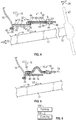
- FIG. 4 is a sectional side view of the instrument panel 10 and the interior trim gap covering apparatus 16 depicted in FIG. 2 along line 4-4 in accordance with an exemplary embodiment.
- the instrument panel 10 has a cavity 18 below a cluster bezel 19 through which the steering column 12 extends for coupling to a structure (not shown) under the instrument panel 10.
- the cavity 18 is sized to allow for tilt (indicated by arrows 20) and full travel along an axial direction (indicated by double headed arrow 22) of a steering wheel 23 (shown in dashed lines) that is operatively coupled to the steering column 12 as well as for unimpeded translational movement of the steering column 12 along the axial direction 22 for a specified axial distance during a vehicle collision.
- a gap 24 that exposes the steering column 12 and a lower opening portion 26 of the instrument panel 10.
- the inner and outer gap hider members 14 and 15 are positioned adjacent to each other in which the outer gap hider member partially overlaps the inner gap hider member 14 to cover or otherwise obstruct a vehicle occupant's view 28 of the gap 24.
- the inner and outer gap hider members are free to move (e.g., translate) relative to one another generally along an axis 30 that may be parallel or at a slight angle (e.g., about 30° or less) relative to the axial direction 22 to advantageously cover the gap 24 while allowing for full travel and tilt of the steering wheel 23.
- the inner gap hider member 14 comprises a rigid substrate 32 and an outer covering 34 that overlies the rigid substrate 32.
- the rigid substrate 32 may be formed, for example, via injection molding of a polymeric material such as polypropylene (PP), polycarbonate (PC), ABS, styrene maleic anhydride (SMA), polyamide (PA), polyester (PE), or the like. Additionally, the polymeric material may be unfilled, filled, or compounded to help provide sufficient structure for rigidly supporting the outer covering 34. Other polymeric materials for molding plastic substrates known to those skilled in the art may also be used.
- the outer covering 34 may be a coating, such as a decorative paint, a skin material such as a polyvinyl chloride (PVC)/vinyl skin, a thermoplastic olefin (TPO) skin, a polyurethane (PU or TPU) skin, or the like and/or a laminate structure such as a foam layer with an overlying skin material to provide an aesthetical outer surface.
- the inner gap hider member 14 is attached or otherwise operatively coupled to the instrument panel 10 over the lower opening portion 26, for example, via a molded-in feature 36 or the like that extends from a generally vertical leg portion 33 of the inner gap hider member 14.
- the inner gap hider member 14 advantageously has an "L" cross-sectional shape in which a generally horizontal leg portion 35 extends from the generally vertical leg portion 33 towards the steering wheel 23 to partially cover the gap 24.
- FIG. 3 is a rear perspective view of the outer gap hider member 15 of the interior trim gap covering apparatus 16 in accordance with an exemplary embodiment.
- the outer gap hider member 15 comprises a substrate 40 and a flexible covering 42 that overlies the substrate 40.
- the substrate 40 has a forward edge 44 and a rearward edge 46 and may, for example, have an arcuate panel-like shape for radially positioning around the steering column 12.
- openings 48 Formed through the substrate 40 are openings 48 that extend between the forward and rearward edges 44 and 46. As will be discussed in further detail below, the openings 48 facilitate the substrate 40 deforming in response to an applied force.
- the openings 48 are configured as elongated openings such as slots 50, or may have an alternative shape, such as, for example, a diamond-shaped opening 52 (indicated by dashed line) to advantageously facilitate the substrate 40 deforming.
- the openings 48 have a length (indicated by double headed arrow 54) of from about 10 to about 50 mm and a width (indicated by arrows 56) of from about 5 to about 12 mm to advantageously facilitate the substrate 40 deforming.
- the openings 48 are arranged as a plurality of juxtaposed elongated openings that are spaced apart from each other a distance (indicated by double headed arrow 58) of from about 10 to about 30 mm to advantageously facilitate the substrate 40 deforming.
- the substrate 40 is formed of a semi-rigid polymeric material such as polypropylene (PP) that allows for some elastic and/or plastic deformation without breaking.
- the semi-rigid polymeric material may be formed into a sheet having a thickness of from about 0.75 to about 2.5 mm and subsequently die cut, for example, to form the openings 48 through the substrate 40.
- the flexible covering 42 comprises an outer skin 60.
- the outer skin 60 may be formed from a PVC/vinyl skin, a TPO skin, a polyurethane PU or TPU skin, or the like.
- the flexible covering 42 may further comprise a foam layer 62 that is disposed under the outer skin 60.
- the foam layer 62 may be integrally formed with the outer skin 60 such as via a co-extrusion process to form a bi-laminate or multi-laminate structure, or alternatively, may be a separate layer from the outer skin 60.
- the flexible covering 42 is sown (via stitching 63) or otherwise attached to the substrate 40 proximate the forward and rearward edges 44 and 46.
- the outer gap hider member 15 further includes a steering wheel shroud 64 that is coupled to the substrate 40 and that is operatively couple to a steering column 12.
- the steering wheel shroud 64 has molded posts 66 (e.g., which may be configured as heat stakes if desired) that extend through openings 68 in the substrate 40 to couple the steering wheel shroud 64 to the substrate 40.
- the steering wheel shroud 64 may be molded using a polymeric material such as PP, PC, ABS, PA, PE, or the like and decorated using, for example, a molded-in color and/or pigment or a decorative paint.
- FIG. 5 is a sectional side view of the instrument panel 10 and the interior trim gap covering apparatus 16 similar to the depiction in FIG. 4 but illustrating the interior trim gap covering apparatus 16 deforming in response to an applied force (indicated by arrow 70).
- the substrate 40 elastically and/or plastically deforms in response to the applied force 70, such as when the steering column 12 translates generally towards the instrument panel 10 a specified axial distance during a frontal impact, for example.
- the openings 48 locally weaken a center section of the substrate 40 so that when the applied force 70 is translated, for example, through the steering wheel shroud 64 to the substrate 40, the area(s) of the substrate 40 surrounding the openings 48 can bend and/or otherwise deform to help reduce stresses from concentrating in various areas of the substrate 40 and/or other areas of the outer gap hider member 15 to help prevent breakage of the outer gap hider member 15 and/or to allow the steering column 12 to collapse beyond its travel position without restriction from a rigid trim component(s).
- the flexible covering 42 is sufficiently flexible to move and flex with corresponding movement and deformation of the substrate 40.
- a method of forming an interior trim gap covering apparatus for a motor vehicle comprises the steps of forming (step 100) a plurality of openings through a substrate extending between a forward edge and a rearward edge of the substrate.
- the openings are configured to facilitate the substrate deforming in response to an applied force.
- the substrate is covered (step 102) with a flexible covering to form a gap hider member.
Landscapes
- Engineering & Computer Science (AREA)
- Mechanical Engineering (AREA)
- Chemical & Material Sciences (AREA)
- Combustion & Propulsion (AREA)
- Transportation (AREA)
- Automation & Control Theory (AREA)
- Vehicle Interior And Exterior Ornaments, Soundproofing, And Insulation (AREA)
- Instrument Panels (AREA)
- Steering Controls (AREA)
Claims (14)
- Dispositif de recouvrement d'espace de garniture intérieure (16) pour recouvrir un espace qui expose une partie d'une colonne de direction et/ou d'un tableau de bord d'un véhicule automobile, l'appareil comprenant:un premier élément de cache d'espace (14) comprenant:
une enveloppe de volant de direction (64) et un substrat (40), dans lequel l'enveloppe de volant de direction est couplée au substrat et est configurée pour se coupler de manière opérationnelle à une colonne de direction (12),dans lequel le substrat a un bord avant (44) et un bord arrière (46) et une pluralité d'ouvertures (48) formés à travers ceux-ci s'étendant entre les bords avant et arrière pour faciliter la déformation du substrat en réponse à une force appliquée; etdans lequel une couverture souple (42) recouvre le substrat. - Appareil selon la revendication 1, dans lequel les ouvertures sont configurées comme des ouvertures en forme de losange.
- Appareil selon la revendication 1, dans lequel les ouvertures sont configurées comme des fentes.
- Appareil selon la revendication 1, dans lequel les ouvertures sont configurées comme une pluralité d'ouvertures allongées juxtaposées.
- Appareil selon la revendication 1, dans lequel le revêtement souple comprend une peau externe (60).
- Appareil selon la revendication 5, dans lequel le revêtement flexible comprend en outre une couche de mousse (62) qui est disposée entre la peau externe et le substrat.
- Appareil selon la revendication 1, comprenant en outre un second élément de cache d'espace (15) qui est configuré pour se positionner adjacent au premier élément de cache d'espace et se déplacer par rapport au premier élément de cache d'espace généralement le long d'un axe.
- Appareil selon la revendication 7, dans lequel le second élément de cache d'espace est configuré pour être couplé de manière opérationnelle à un tableau de bord (10) et le premier élément de cache est configuré pour être couplé de façon opérationnelle à la colonne de direction et le premier et le second éléments de cache d'espace sont configurés en coopération pour couvrir l'espace qui expose une partie de la colonne de direction et/ou du tableau de bord.
- L'appareil de la revendication 7, dans lequel le second élément de cache d'espace comprend;
un substrat rigide (32); et
un revêtement extérieur (34) recouvrant le substrat rigide. - Appareil selon la revendication 1, dans lequel les ouvertures ont chacune une longueur d'environ 10 à environ 50 mm.
- Appareil selon la revendication 1, dans lequel les ouvertures ont chacune une largeur d'environ 5 à environ 12 mm.
- Appareil selon la revendication 1, dans lequel les ouvertures sont espacées les unes des autres d'une distance d'environ 10 à environ 30 mm.
- Appareil selon la revendication 1, dans lequel le substrat a une épaisseur d'environ 0,75 à environ 2,5 mm.
- Procédé (100) de recouvrement d'espace de garniture intérieure pour recouvrir un espace qui expose une partie d'une colonne de direction et/ou d'un tableau de bord d'un véhicule automobile, le procédé comprenant les étapes consistant à:former (102) une pluralité d'ouvertures à travers un substrat s'étendant entre un bord avant et un bord arrière du substrat, dans lequel les ouvertures sont configurées pour faciliter la déformation du substrat en réponse à une force appliquée; etrecouvrir (104) le substrat avec un revêtement souple pour former un élément de cache d'espace;dans lequel l'élément de cache d'espace comprend une enveloppe de volant de direction et le substrat, dans lequel l'enveloppe de volant de direction est couplée au substrat et est configurée pour se coupler de manière opérationnelle à une colonne de direction.
Applications Claiming Priority (1)
| Application Number | Priority Date | Filing Date | Title |
|---|---|---|---|
| US14/729,638 US9566928B2 (en) | 2015-06-03 | 2015-06-03 | Interior trim gap covering apparatuses for motor vehicles and methods for making the same |
Publications (3)
| Publication Number | Publication Date |
|---|---|
| EP3100932A1 EP3100932A1 (fr) | 2016-12-07 |
| EP3100932A8 EP3100932A8 (fr) | 2018-05-23 |
| EP3100932B1 true EP3100932B1 (fr) | 2018-09-26 |
Family
ID=57450906
Family Applications (1)
| Application Number | Title | Priority Date | Filing Date |
|---|---|---|---|
| EP16172239.2A Active EP3100932B1 (fr) | 2015-06-03 | 2016-05-31 | Appareils de recouvrement d'interstice de garniture intérieure pour véhicules automobiles et procédés de fabrication de ceux-ci |
Country Status (4)
| Country | Link |
|---|---|
| US (1) | US9566928B2 (fr) |
| EP (1) | EP3100932B1 (fr) |
| CN (1) | CN205819305U (fr) |
| BR (1) | BR102016012760B1 (fr) |
Families Citing this family (13)
| Publication number | Priority date | Publication date | Assignee | Title |
|---|---|---|---|---|
| JP6406716B2 (ja) * | 2016-03-07 | 2018-10-17 | 本田技研工業株式会社 | コラムブラインド装置 |
| FR3078038B1 (fr) * | 2018-02-20 | 2020-03-13 | Faurecia Interieur Industrie | Element de garnissage comprenant une surface externe deformable par deux elements d'actionnement |
| JP6833747B2 (ja) * | 2018-03-13 | 2021-02-24 | 株式会社豊田自動織機 | 車両の間隙遮蔽構造 |
| FR3085645B1 (fr) | 2018-09-11 | 2021-04-09 | Psa Automobiles Sa | Ensemble formant une gaine d’habillage de colonne de direction et vehicule presentant une telle gaine |
| FR3100788B1 (fr) * | 2019-09-16 | 2021-12-17 | Renault Sas | Element d’habillage d’une colonne de direction de vehicule automobile |
| FR3105122B1 (fr) * | 2019-12-23 | 2022-01-07 | Faurecia Interieur Ind | Elément de garnissage pour véhicule comprenant une couture et un élément de protection de la couture |
| JP7272990B2 (ja) * | 2020-04-09 | 2023-05-12 | トヨタ自動車株式会社 | コラムカバーユニット |
| DE102020111495A1 (de) | 2020-04-28 | 2021-10-28 | Audi Aktiengesellschaft | Vorrichtung zur Abdeckung eines Spalts zwischen einer Instrumententafel und einer Lenksäule und Kraftfahrzeug |
| US11577608B2 (en) * | 2020-09-11 | 2023-02-14 | Manuel Martinez | Dashboard cover sheet |
| US11707985B2 (en) | 2020-10-01 | 2023-07-25 | Ford Global Technologies, Llc | Steering column induced break away |
| JP7440451B2 (ja) | 2021-03-31 | 2024-02-28 | トヨタ自動車株式会社 | 自動車 |
| JP7440450B2 (ja) * | 2021-03-31 | 2024-02-28 | トヨタ自動車株式会社 | 自動車 |
| US12559047B2 (en) * | 2023-01-11 | 2026-02-24 | Ford Global Technologies, Llc | Shrouds for stowable steering columns |
Family Cites Families (17)
| Publication number | Priority date | Publication date | Assignee | Title |
|---|---|---|---|---|
| JPS60226357A (ja) | 1984-04-24 | 1985-11-11 | Nissan Motor Co Ltd | コラムカバ− |
| JPS6325679U (fr) | 1986-08-04 | 1988-02-19 | ||
| DE4337721C1 (de) | 1993-11-05 | 1995-02-23 | Bayerische Motoren Werke Ag | Spaltabdeckung an einer verstellbaren Lenksäule eines Kraftfahrzeugs |
| US5813288A (en) * | 1996-08-08 | 1998-09-29 | Chrysler Corporation | Steering column close-out boot |
| DE19644170C2 (de) * | 1996-10-24 | 2001-02-22 | Opel Adam Ag | Verkleidung für eine axial und in der Höhe verstellbare Lenksäule |
| CA2462024A1 (fr) | 2001-10-04 | 2003-04-10 | James Richard Lytle | Tableau de bord presentant un carter renfermant la colonne de direction souple et procede d'assemblage |
| DE10242966B3 (de) | 2002-09-17 | 2004-06-03 | Dr.Ing.H.C. F. Porsche Ag | Flexible Spaltabdeckung zwischen einer verstellbaren Lenksäule eines Kraftfahrzeuges und einer Armaturentafel |
| JP2008254480A (ja) | 2007-04-02 | 2008-10-23 | Calsonic Kansei Corp | ステアリングコラム部中見得防止構造 |
| JP4988471B2 (ja) * | 2007-07-31 | 2012-08-01 | 日本プラスト株式会社 | 車両の内装構造 |
| JP5137743B2 (ja) | 2008-08-25 | 2013-02-06 | ダイキョーニシカワ株式会社 | エアバッグドア及びその製造方法 |
| DE102008054359A1 (de) | 2008-11-03 | 2010-05-06 | Bayerische Motoren Werke Aktiengesellschaft | Spaltabdeckung an einer verstellbaren Lenksäule eines Kraftfahrzeugs |
| JP5686529B2 (ja) | 2010-05-07 | 2015-03-18 | 本田技研工業株式会社 | 車両用ステアリング遮蔽装置の取付方法及び車両用ステアリング遮蔽装置 |
| US8567815B2 (en) | 2011-09-08 | 2013-10-29 | Faurecia Interior Systems, Inc. | Limiting energy leakage during laser scoring of vehicle airbag coverings |
| FR2982571B1 (fr) * | 2011-11-14 | 2013-12-20 | Peugeot Citroen Automobiles Sa | Piece de garnissage d'une colonne de direction de vehicule automobile |
| KR101962466B1 (ko) | 2012-09-28 | 2019-03-26 | 현대모비스 주식회사 | 자동차 |
| DE102012023944A1 (de) | 2012-12-06 | 2014-06-12 | Audi Ag | Anordnung zur Spaltabdeckung für einen veränderlichen Spalt an einer verstellbaren Lenksäule eines Fahrzeugs |
| US9463723B2 (en) * | 2014-04-07 | 2016-10-11 | Ford Global Technologies, Llc | Armrest substrate having detachable elongated support bands |
-
2015
- 2015-06-03 US US14/729,638 patent/US9566928B2/en active Active
-
2016
- 2016-05-31 EP EP16172239.2A patent/EP3100932B1/fr active Active
- 2016-06-03 BR BR102016012760-2A patent/BR102016012760B1/pt active IP Right Grant
- 2016-06-03 CN CN201620529527.8U patent/CN205819305U/zh active Active
Non-Patent Citations (1)
| Title |
|---|
| None * |
Also Published As
| Publication number | Publication date |
|---|---|
| US9566928B2 (en) | 2017-02-14 |
| CN205819305U (zh) | 2016-12-21 |
| US20160355145A1 (en) | 2016-12-08 |
| EP3100932A1 (fr) | 2016-12-07 |
| BR102016012760A2 (pt) | 2016-12-06 |
| BR102016012760B1 (pt) | 2023-02-28 |
| EP3100932A8 (fr) | 2018-05-23 |
Similar Documents
| Publication | Publication Date | Title |
|---|---|---|
| EP3100932B1 (fr) | Appareils de recouvrement d'interstice de garniture intérieure pour véhicules automobiles et procédés de fabrication de ceux-ci | |
| US8297674B2 (en) | Vehicle interior trim panel | |
| CN101570140B (zh) | 仪表板和遮蔽部件 | |
| US8186709B2 (en) | Vehicle interior trim panel | |
| US9102298B2 (en) | Foam-in-place interior panels having integrated airbag doors including substrates with airbag chute-door assemblies for motor vehicles | |
| US8297645B2 (en) | Vehicle interior trim panel | |
| US7922189B1 (en) | Vehicle grip assist handle | |
| US8303010B2 (en) | Vehicle interior trim panel | |
| EP2853450B1 (fr) | Panneau de finition de groupe d'instruments | |
| CN110171365B (zh) | 包括具有信息显示装置的可变形外表面的饰件 | |
| EP2569188B1 (fr) | Ensemble intérieur de véhicule | |
| EP2460696A1 (fr) | Lignes de rupture amélioré pour couvercle de module de coussin gonflable | |
| US9073508B1 (en) | Driver airbag to steering wheel gap reduction | |
| CN214355850U (zh) | 用于车辆的车顶内衬 | |
| US10137854B2 (en) | Headliner assembly for a vehicle and a vehicle system using the same | |
| GB2428222A (en) | Trim panel with rupture line | |
| US7150488B2 (en) | Instrument panel having flexible steering wheel column closeout | |
| EP2783923B1 (fr) | Boîtier d'airbag | |
| US20090115228A1 (en) | Vehicle roof | |
| EP1963142A1 (fr) | Panneau de garniture pour l'interieur d'un vehicule a moteur et procede de fabrication d'un tel panneau de garniture | |
| JP7811759B2 (ja) | 乗物用把持部材 | |
| JP2005313727A (ja) | 車両の内装部材とステアリングコラムとの隙間遮蔽構造 | |
| GB2335257A (en) | A cowl arrangement for a vehicle steering column |
Legal Events
| Date | Code | Title | Description |
|---|---|---|---|
| PUAI | Public reference made under article 153(3) epc to a published international application that has entered the european phase |
Free format text: ORIGINAL CODE: 0009012 |
|
| STAA | Information on the status of an ep patent application or granted ep patent |
Free format text: STATUS: THE APPLICATION HAS BEEN PUBLISHED |
|
| AK | Designated contracting states |
Kind code of ref document: A1 Designated state(s): AL AT BE BG CH CY CZ DE DK EE ES FI FR GB GR HR HU IE IS IT LI LT LU LV MC MK MT NL NO PL PT RO RS SE SI SK SM TR |
|
| AX | Request for extension of the european patent |
Extension state: BA ME |
|
| STAA | Information on the status of an ep patent application or granted ep patent |
Free format text: STATUS: REQUEST FOR EXAMINATION WAS MADE |
|
| 17P | Request for examination filed |
Effective date: 20170419 |
|
| RBV | Designated contracting states (corrected) |
Designated state(s): AL AT BE BG CH CY CZ DE DK EE ES FI FR GB GR HR HU IE IS IT LI LT LU LV MC MK MT NL NO PL PT RO RS SE SI SK SM TR |
|
| RIC1 | Information provided on ipc code assigned before grant |
Ipc: B62D 1/187 20060101AFI20180227BHEP |
|
| GRAP | Despatch of communication of intention to grant a patent |
Free format text: ORIGINAL CODE: EPIDOSNIGR1 |
|
| STAA | Information on the status of an ep patent application or granted ep patent |
Free format text: STATUS: GRANT OF PATENT IS INTENDED |
|
| INTG | Intention to grant announced |
Effective date: 20180426 |
|
| GRAS | Grant fee paid |
Free format text: ORIGINAL CODE: EPIDOSNIGR3 |
|
| GRAA | (expected) grant |
Free format text: ORIGINAL CODE: 0009210 |
|
| STAA | Information on the status of an ep patent application or granted ep patent |
Free format text: STATUS: THE PATENT HAS BEEN GRANTED |
|
| AK | Designated contracting states |
Kind code of ref document: B1 Designated state(s): AL AT BE BG CH CY CZ DE DK EE ES FI FR GB GR HR HU IE IS IT LI LT LU LV MC MK MT NL NO PL PT RO RS SE SI SK SM TR |
|
| REG | Reference to a national code |
Ref country code: GB Ref legal event code: FG4D |
|
| REG | Reference to a national code |
Ref country code: CH Ref legal event code: EP |
|
| REG | Reference to a national code |
Ref country code: AT Ref legal event code: REF Ref document number: 1045654 Country of ref document: AT Kind code of ref document: T Effective date: 20181015 |
|
| REG | Reference to a national code |
Ref country code: IE Ref legal event code: FG4D |
|
| REG | Reference to a national code |
Ref country code: DE Ref legal event code: R096 Ref document number: 602016005904 Country of ref document: DE |
|
| REG | Reference to a national code |
Ref country code: NL Ref legal event code: MP Effective date: 20180926 |
|
| PG25 | Lapsed in a contracting state [announced via postgrant information from national office to epo] |
Ref country code: FI Free format text: LAPSE BECAUSE OF FAILURE TO SUBMIT A TRANSLATION OF THE DESCRIPTION OR TO PAY THE FEE WITHIN THE PRESCRIBED TIME-LIMIT Effective date: 20180926 Ref country code: BG Free format text: LAPSE BECAUSE OF FAILURE TO SUBMIT A TRANSLATION OF THE DESCRIPTION OR TO PAY THE FEE WITHIN THE PRESCRIBED TIME-LIMIT Effective date: 20181226 Ref country code: NO Free format text: LAPSE BECAUSE OF FAILURE TO SUBMIT A TRANSLATION OF THE DESCRIPTION OR TO PAY THE FEE WITHIN THE PRESCRIBED TIME-LIMIT Effective date: 20181226 Ref country code: RS Free format text: LAPSE BECAUSE OF FAILURE TO SUBMIT A TRANSLATION OF THE DESCRIPTION OR TO PAY THE FEE WITHIN THE PRESCRIBED TIME-LIMIT Effective date: 20180926 Ref country code: LT Free format text: LAPSE BECAUSE OF FAILURE TO SUBMIT A TRANSLATION OF THE DESCRIPTION OR TO PAY THE FEE WITHIN THE PRESCRIBED TIME-LIMIT Effective date: 20180926 Ref country code: GR Free format text: LAPSE BECAUSE OF FAILURE TO SUBMIT A TRANSLATION OF THE DESCRIPTION OR TO PAY THE FEE WITHIN THE PRESCRIBED TIME-LIMIT Effective date: 20181227 |
|
| REG | Reference to a national code |
Ref country code: LT Ref legal event code: MG4D |
|
| PG25 | Lapsed in a contracting state [announced via postgrant information from national office to epo] |
Ref country code: LV Free format text: LAPSE BECAUSE OF FAILURE TO SUBMIT A TRANSLATION OF THE DESCRIPTION OR TO PAY THE FEE WITHIN THE PRESCRIBED TIME-LIMIT Effective date: 20180926 Ref country code: AL Free format text: LAPSE BECAUSE OF FAILURE TO SUBMIT A TRANSLATION OF THE DESCRIPTION OR TO PAY THE FEE WITHIN THE PRESCRIBED TIME-LIMIT Effective date: 20180926 Ref country code: HR Free format text: LAPSE BECAUSE OF FAILURE TO SUBMIT A TRANSLATION OF THE DESCRIPTION OR TO PAY THE FEE WITHIN THE PRESCRIBED TIME-LIMIT Effective date: 20180926 |
|
| REG | Reference to a national code |
Ref country code: AT Ref legal event code: MK05 Ref document number: 1045654 Country of ref document: AT Kind code of ref document: T Effective date: 20180926 |
|
| PG25 | Lapsed in a contracting state [announced via postgrant information from national office to epo] |
Ref country code: ES Free format text: LAPSE BECAUSE OF FAILURE TO SUBMIT A TRANSLATION OF THE DESCRIPTION OR TO PAY THE FEE WITHIN THE PRESCRIBED TIME-LIMIT Effective date: 20180926 Ref country code: IS Free format text: LAPSE BECAUSE OF FAILURE TO SUBMIT A TRANSLATION OF THE DESCRIPTION OR TO PAY THE FEE WITHIN THE PRESCRIBED TIME-LIMIT Effective date: 20190126 Ref country code: PL Free format text: LAPSE BECAUSE OF FAILURE TO SUBMIT A TRANSLATION OF THE DESCRIPTION OR TO PAY THE FEE WITHIN THE PRESCRIBED TIME-LIMIT Effective date: 20180926 Ref country code: CZ Free format text: LAPSE BECAUSE OF FAILURE TO SUBMIT A TRANSLATION OF THE DESCRIPTION OR TO PAY THE FEE WITHIN THE PRESCRIBED TIME-LIMIT Effective date: 20180926 Ref country code: EE Free format text: LAPSE BECAUSE OF FAILURE TO SUBMIT A TRANSLATION OF THE DESCRIPTION OR TO PAY THE FEE WITHIN THE PRESCRIBED TIME-LIMIT Effective date: 20180926 Ref country code: AT Free format text: LAPSE BECAUSE OF FAILURE TO SUBMIT A TRANSLATION OF THE DESCRIPTION OR TO PAY THE FEE WITHIN THE PRESCRIBED TIME-LIMIT Effective date: 20180926 Ref country code: RO Free format text: LAPSE BECAUSE OF FAILURE TO SUBMIT A TRANSLATION OF THE DESCRIPTION OR TO PAY THE FEE WITHIN THE PRESCRIBED TIME-LIMIT Effective date: 20180926 Ref country code: NL Free format text: LAPSE BECAUSE OF FAILURE TO SUBMIT A TRANSLATION OF THE DESCRIPTION OR TO PAY THE FEE WITHIN THE PRESCRIBED TIME-LIMIT Effective date: 20180926 |
|
| PG25 | Lapsed in a contracting state [announced via postgrant information from national office to epo] |
Ref country code: SM Free format text: LAPSE BECAUSE OF FAILURE TO SUBMIT A TRANSLATION OF THE DESCRIPTION OR TO PAY THE FEE WITHIN THE PRESCRIBED TIME-LIMIT Effective date: 20180926 Ref country code: PT Free format text: LAPSE BECAUSE OF FAILURE TO SUBMIT A TRANSLATION OF THE DESCRIPTION OR TO PAY THE FEE WITHIN THE PRESCRIBED TIME-LIMIT Effective date: 20190126 Ref country code: SK Free format text: LAPSE BECAUSE OF FAILURE TO SUBMIT A TRANSLATION OF THE DESCRIPTION OR TO PAY THE FEE WITHIN THE PRESCRIBED TIME-LIMIT Effective date: 20180926 |
|
| REG | Reference to a national code |
Ref country code: DE Ref legal event code: R097 Ref document number: 602016005904 Country of ref document: DE |
|
| PG25 | Lapsed in a contracting state [announced via postgrant information from national office to epo] |
Ref country code: DK Free format text: LAPSE BECAUSE OF FAILURE TO SUBMIT A TRANSLATION OF THE DESCRIPTION OR TO PAY THE FEE WITHIN THE PRESCRIBED TIME-LIMIT Effective date: 20180926 |
|
| PLBE | No opposition filed within time limit |
Free format text: ORIGINAL CODE: 0009261 |
|
| STAA | Information on the status of an ep patent application or granted ep patent |
Free format text: STATUS: NO OPPOSITION FILED WITHIN TIME LIMIT |
|
| 26N | No opposition filed |
Effective date: 20190627 |
|
| PG25 | Lapsed in a contracting state [announced via postgrant information from national office to epo] |
Ref country code: SI Free format text: LAPSE BECAUSE OF FAILURE TO SUBMIT A TRANSLATION OF THE DESCRIPTION OR TO PAY THE FEE WITHIN THE PRESCRIBED TIME-LIMIT Effective date: 20180926 |
|
| REG | Reference to a national code |
Ref country code: CH Ref legal event code: PL |
|
| PG25 | Lapsed in a contracting state [announced via postgrant information from national office to epo] |
Ref country code: MC Free format text: LAPSE BECAUSE OF FAILURE TO SUBMIT A TRANSLATION OF THE DESCRIPTION OR TO PAY THE FEE WITHIN THE PRESCRIBED TIME-LIMIT Effective date: 20180926 Ref country code: LI Free format text: LAPSE BECAUSE OF NON-PAYMENT OF DUE FEES Effective date: 20190531 Ref country code: CH Free format text: LAPSE BECAUSE OF NON-PAYMENT OF DUE FEES Effective date: 20190531 |
|
| REG | Reference to a national code |
Ref country code: BE Ref legal event code: MM Effective date: 20190531 |
|
| PG25 | Lapsed in a contracting state [announced via postgrant information from national office to epo] |
Ref country code: LU Free format text: LAPSE BECAUSE OF NON-PAYMENT OF DUE FEES Effective date: 20190531 |
|
| PG25 | Lapsed in a contracting state [announced via postgrant information from national office to epo] |
Ref country code: TR Free format text: LAPSE BECAUSE OF FAILURE TO SUBMIT A TRANSLATION OF THE DESCRIPTION OR TO PAY THE FEE WITHIN THE PRESCRIBED TIME-LIMIT Effective date: 20180926 |
|
| PG25 | Lapsed in a contracting state [announced via postgrant information from national office to epo] |
Ref country code: IE Free format text: LAPSE BECAUSE OF NON-PAYMENT OF DUE FEES Effective date: 20190531 |
|
| PG25 | Lapsed in a contracting state [announced via postgrant information from national office to epo] |
Ref country code: BE Free format text: LAPSE BECAUSE OF NON-PAYMENT OF DUE FEES Effective date: 20190531 |
|
| GBPC | Gb: european patent ceased through non-payment of renewal fee |
Effective date: 20200531 |
|
| PG25 | Lapsed in a contracting state [announced via postgrant information from national office to epo] |
Ref country code: GB Free format text: LAPSE BECAUSE OF NON-PAYMENT OF DUE FEES Effective date: 20200531 |
|
| PG25 | Lapsed in a contracting state [announced via postgrant information from national office to epo] |
Ref country code: CY Free format text: LAPSE BECAUSE OF FAILURE TO SUBMIT A TRANSLATION OF THE DESCRIPTION OR TO PAY THE FEE WITHIN THE PRESCRIBED TIME-LIMIT Effective date: 20180926 |
|
| PG25 | Lapsed in a contracting state [announced via postgrant information from national office to epo] |
Ref country code: SE Free format text: LAPSE BECAUSE OF NON-PAYMENT OF DUE FEES Effective date: 20180926 |
|
| PG25 | Lapsed in a contracting state [announced via postgrant information from national office to epo] |
Ref country code: MT Free format text: LAPSE BECAUSE OF FAILURE TO SUBMIT A TRANSLATION OF THE DESCRIPTION OR TO PAY THE FEE WITHIN THE PRESCRIBED TIME-LIMIT Effective date: 20180926 Ref country code: HU Free format text: LAPSE BECAUSE OF FAILURE TO SUBMIT A TRANSLATION OF THE DESCRIPTION OR TO PAY THE FEE WITHIN THE PRESCRIBED TIME-LIMIT; INVALID AB INITIO Effective date: 20160531 |
|
| PGFP | Annual fee paid to national office [announced via postgrant information from national office to epo] |
Ref country code: DE Payment date: 20210421 Year of fee payment: 6 |
|
| PG25 | Lapsed in a contracting state [announced via postgrant information from national office to epo] |
Ref country code: MK Free format text: LAPSE BECAUSE OF FAILURE TO SUBMIT A TRANSLATION OF THE DESCRIPTION OR TO PAY THE FEE WITHIN THE PRESCRIBED TIME-LIMIT Effective date: 20180926 |
|
| REG | Reference to a national code |
Ref country code: DE Ref legal event code: R119 Ref document number: 602016005904 Country of ref document: DE |
|
| PG25 | Lapsed in a contracting state [announced via postgrant information from national office to epo] |
Ref country code: DE Free format text: LAPSE BECAUSE OF NON-PAYMENT OF DUE FEES Effective date: 20221201 |
|
| P01 | Opt-out of the competence of the unified patent court (upc) registered |
Effective date: 20230518 |
|
| PGFP | Annual fee paid to national office [announced via postgrant information from national office to epo] |
Ref country code: IT Payment date: 20250423 Year of fee payment: 10 |
|
| PGFP | Annual fee paid to national office [announced via postgrant information from national office to epo] |
Ref country code: FR Payment date: 20250424 Year of fee payment: 10 |