EP3100933B1 - Rotationsbewegungsvorrichtung - Google Patents
Rotationsbewegungsvorrichtung Download PDFInfo
- Publication number
- EP3100933B1 EP3100933B1 EP16172094.1A EP16172094A EP3100933B1 EP 3100933 B1 EP3100933 B1 EP 3100933B1 EP 16172094 A EP16172094 A EP 16172094A EP 3100933 B1 EP3100933 B1 EP 3100933B1
- Authority
- EP
- European Patent Office
- Prior art keywords
- groove
- protrusion
- holder
- case
- protrusions
- Prior art date
- Legal status (The legal status is an assumption and is not a legal conclusion. Google has not performed a legal analysis and makes no representation as to the accuracy of the status listed.)
- Not-in-force
Links
- 238000004804 winding Methods 0.000 claims description 24
- 238000006243 chemical reaction Methods 0.000 description 16
- 125000006850 spacer group Chemical group 0.000 description 4
- 230000007423 decrease Effects 0.000 description 1
- 238000006073 displacement reaction Methods 0.000 description 1
- 238000004519 manufacturing process Methods 0.000 description 1
- 239000002184 metal Substances 0.000 description 1
- 238000000034 method Methods 0.000 description 1
Images


Classifications
-
- B—PERFORMING OPERATIONS; TRANSPORTING
- B62—LAND VEHICLES FOR TRAVELLING OTHERWISE THAN ON RAILS
- B62D—MOTOR VEHICLES; TRAILERS
- B62D1/00—Steering controls, i.e. means for initiating a change of direction of the vehicle
- B62D1/02—Steering controls, i.e. means for initiating a change of direction of the vehicle vehicle-mounted
- B62D1/16—Steering columns
-
- B—PERFORMING OPERATIONS; TRANSPORTING
- B62—LAND VEHICLES FOR TRAVELLING OTHERWISE THAN ON RAILS
- B62D—MOTOR VEHICLES; TRAILERS
- B62D5/00—Power-assisted or power-driven steering
- B62D5/001—Mechanical components or aspects of steer-by-wire systems, not otherwise provided for in this maingroup
- B62D5/005—Mechanical components or aspects of steer-by-wire systems, not otherwise provided for in this maingroup means for generating torque on steering wheel or input member, e.g. feedback
-
- G—PHYSICS
- G05—CONTROLLING; REGULATING
- G05G—CONTROL DEVICES OR SYSTEMS INSOFAR AS CHARACTERISED BY MECHANICAL FEATURES ONLY
- G05G5/00—Means for preventing, limiting or returning the movements of parts of a control mechanism, e.g. locking controlling member
- G05G5/05—Means for returning or tending to return controlling members to an inoperative or neutral position, e.g. by providing return springs or resilient end-stops
-
- G—PHYSICS
- G05—CONTROLLING; REGULATING
- G05G—CONTROL DEVICES OR SYSTEMS INSOFAR AS CHARACTERISED BY MECHANICAL FEATURES ONLY
- G05G1/00—Controlling members, e.g. knobs or handles; Assemblies or arrangements thereof; Indicating position of controlling members
- G05G1/08—Controlling members for hand actuation by rotary movement, e.g. hand wheels
-
- G—PHYSICS
- G05—CONTROLLING; REGULATING
- G05G—CONTROL DEVICES OR SYSTEMS INSOFAR AS CHARACTERISED BY MECHANICAL FEATURES ONLY
- G05G5/00—Means for preventing, limiting or returning the movements of parts of a control mechanism, e.g. locking controlling member
- G05G5/03—Means for enhancing the operator's awareness of arrival of the controlling member at a command or datum position; Providing feel, e.g. means for creating a counterforce
Definitions
- This disclosure relates to a rotational operation device that uses a torsion coil spring to generate an operational reaction force.
- Japanese Laid-Open Patent Publication No. 2014-41469 describes a prior art example of a rotational operation device.
- the rotational operation device described in the publication includes a steering shaft, a holder, a torsion coil spring, and a case.
- the steering shaft rotates integrally with a steering wheel.
- the holder is fixed to the steering shaft.
- the torsion coil spring is fitted onto the steering shaft.
- the case accommodates the holder and the torsion coil spring.
- the torsion coil spring includes two protrusions that are located at opposite ends of the coil.
- the case supports one of the two protrusions in an immovable manner.
- the holder supports the other one of the two protrusions.
- Rotation of the steering shaft applies force to the protrusion supported by the holder and twists the torsion coil spring.
- the twisting force is transmitted as an operational reaction force to the steering wheel. This allows the user to perceive the operational reaction force.
- One embodiment is a rotational operation device including a rotation shaft, a holder, a torsion coil spring, and a case.
- the rotation shaft is rotated when an operation member is rotated.
- the holder is fixed to the rotation shaft.
- the torsion coil spring includes a coil and two protrusions.
- the rotation shaft is inserted through the coil, and the two protrusions are located at opposite ends of the coil.
- the case accommodates the holder and the torsion coil spring.
- the holder and the case are configured to twist the coil when the rotation shaft is rotated by restricting movement of one of the protrusions with the case and pushing the other one of the protrusions in a rotation direction of the rotation shaft with the holder.
- the case includes a first groove that receives the one of the protrusions.
- the holder includes a second groove that receives the other one of the protrusions.
- the two protrusions are spaced apart in an axial direction of the rotation shaft by an interval that is invariable and set by a fixed length between the first groove of the case and the second groove of the holder.
- the fixed length is set to a distance that produces a gap between windings of the coil when the torsion coil spring is in a load-free state, with the two protrusions supported by the first and second grooves.
- Fig. 1 illustrates a steering device 1 that is one example of a rotational operation device.
- the steering device 1 includes a plate 11 fixed to a vehicle body (not illustrated).
- the plate 11 includes a plate hole 12.
- a cylindrical case 13 is fixed to the front surface of the plate 11.
- the cylindrical case 13 extends in the front-rear direction of the steering device 1.
- the cylindrical case 13 is coaxial with the plate hole 12.
- the front end of the cylindrical case 13 includes a flange 14 having a diameter that gradually increases toward the front.
- a spring stopper 15 projects from the inner surface of the cylindrical case 13.
- the spring stopper 15 extends in the axial direction of the cylindrical case 13.
- the inner surface of the cylindrical case 13 includes a first rotation restriction projection 18 and a second rotation restriction projection 19. As illustrated in Fig.
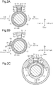
- the spring stopper 15 when viewing the cylindrical case 13 from the front in the axial direction, the spring stopper 15 is located at the twelve o'clock position, the first rotation restriction projection 18 is located at the ten o'clock position, and the second rotation restriction projection 19 is located at the two o'clock position.
- the first rotation restriction projection 18 is located at a position separated by 100° in the clockwise direction from the six o'clock position
- the second rotation restriction projection 19 is located at a position separated by 100° in the counterclockwise direction from the six o'clock position.
- a cover 16 is fixed to the flange 14.
- the cover 16 includes a cover hole 17 that is coaxial with the cylindrical case 13.
- a post-shaped steering shaft 21 is inserted through the plate hole 12 of the plate 11, the cylindrical case 13, and the cover hole 17 of the cover 16.
- the steering shaft 21 is rotationally supported by a plate bearing 22, which is received in the plate hole 12, and a cover bearing 27, which is received in the cover hole 17.
- a steering wheel 20, which is operable by a user, is coupled to the front end of the steering shaft 21.
- the steering wheel 20 corresponds to an operation member, and the steering shaft 21 corresponds to a rotation shaft.
- a gear 31, a holder 32, a rotation stopper 33, and a retaining ring 34 are fitted onto the steering shaft 21 between the cover bearing 27 and the plate bearing 22.
- a rotary damper 35 which is rotationally supported by the flange 14 of the cylindrical case 13, is engaged with the gear 31.
- the rotary damper 35 reduces the rotation speed of the gear 31 and the steering shaft 21.
- the holder 32 includes a cylindrical holder body 32a and a semi-cylindrical step 32b, which is continuous with the rear surface of the holder body 32a.
- the holder body 32a is fitted onto the steering shaft 21. Accordingly, the holder 32 rotates integrally with the steering shaft 21.
- a holder piece 36 extends from the rear side of the semi-cylindrical step 32 in the axial direction of the cylindrical case 13. As illustrated in Fig. 2A , the holder piece 36 is located between the spring stopper 15 and the steering shaft 21 in the vertical direction of the steering device 1 (radial direction of steering shaft 21).
- the holder piece 36 has a dimension in the lateral direction (direction of tangent on outer circumferential surface of steering shaft 21) that is set to be the same as the dimension of the spring stopper 15 in the lateral direction.
- the steering shaft 21 includes a reference position set in alignment with the laterally central part of the holder piece 36 and the laterally central part of the spring stopper 15.
- the rotation stopper 33 is generally cylindrical and rotatable relative to the steering shaft 21. As illustrated in Fig. 2C , a restriction projection 37 projects in the radial direction from the outer circumferential surface of the rotation stopper 33.
- the rotation stopper 33 is arranged so that the first and second rotation restriction projections 18 and 19 are located in the rotation path of the restriction projection 37. Further, the restriction projection 37 is located in the rotation path of the semi-cylindrical step 32b.
- the restriction projection 37 is located at a position separated from the first rotation restriction projection 18 in the counterclockwise direction and separated from the second rotation restriction projection 19 in the clockwise direction.
- the holder 32 rotates and the semi-cylindrical step 32b contacts the restriction projection 37.
- the semi-cylindrical step 32b of the holder 32 pushes the restriction projection 37 and rotates the rotation stopper 33.
- the steering shaft 21 can be rotated to a position where the restriction projection 37, which is pushed by the holder 32, contacts the first rotation restriction projection 18 or the second rotation restriction projection 19.
- the gear 31, the holder 32, and the rotation stopper 33 are in contact with one another in this order in the axial direction.
- the retaining ring 34 restricts axial displacement of the gear 31, the holder 32, and the rotation stopper 33 relative to the steering shaft 21.
- a cylindrical spacer 41 is fitted onto the steering shaft 21 between the retaining ring 34 and the plate bearing 22.
- a torsion spring 42 is fitted onto the spacer 41.
- the torsion spring 42 is formed from a coil of a metal wire wound into a spiral form.
- the torsion spring 42 corresponds to a torsion coil spring.
- the spacer 41 is located between the steering shaft 21 and the torsion spring 42 and prevents contact of the steering shaft 21 with the torsion spring 42.
- the torsion spring 42 includes a coil 43 and first and second protrusions 44 and 45, which are located at the two opposite ends of the coil 43.
- the first protrusion 44 is located at the side closer to the plate 11
- the second protrusion 45 is located at the side closer to the steering wheel 20.
- the first and second protrusions 44 and 45 are upwardly bent parallel to each other. Referring to Fig. 2A , as viewed from the front of the steering shaft 21, the first protrusion 44 is located at the clockwise side of the holder piece 36 and the spring stopper 15. Further, the first protrusion 44 contacts the right surfaces of the holder piece 36 and the spring stopper 15.
- the second protrusion 45 is located at the counterclockwise side of the holder piece 36 and the spring stopper 15. Further, the second protrusion 45 is in contact with the left surfaces of the holder piece 36 and the spring stopper 15.
- the right surface of the spring stopper 15 includes a first groove 51, and the left surface of the holder piece 36 includes a second groove 52.
- the left surface of the spring stopper 15 includes a third groove 53, and the right surface of the holder piece 36 includes a fourth groove 54.
- the first groove 51 in the right surface of the spring stopper 15 and the fourth groove 54 in the right surface of the holder piece 36 define a first cooperative groove that supports the first protrusion 44.
- the third groove 53 in the left surface of the spring stopper 15 and the second groove 52 in the left surface of the holder piece 36 define a second cooperative groove that supports the second protrusion 45.
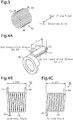
- the distance between the first cooperative groove (51 and 54) and the second cooperative groove (53 and 52) in the axial direction defines a fixed length P that sets the pitch of the windings of the coil 43 in a load-free state (initial state).
- the fixed length P is set to a distance that produces gaps between the windings of the coil 43 when the torsion spring 42 is in the load-free state, with the first and second protrusions 44 and 45 supported by the first and second cooperative grooves.
- the interval L between the first and second protrusions 44 and 45 of the torsion spring 42 in the axial direction is set to the fixed length P between the first and second cooperative grooves.
- the interval L between the first and second protrusions 44 and 45 is invariable and equal to the fixed length P between the first and second cooperative grooves. This restricts axial movement of the first and second protrusions 44 and 45 of the torsion spring 42.
- the holder 32 when the steering shaft 21 is rotated in the counterclockwise direction, the holder 32 is rotated integrally with the steering shaft 21 in the counterclockwise direction.
- the holder piece 36 is also rotated in the counterclockwise direction.
- the left surface of the holder piece 36 is in contact with the second protrusion 45. Accordingly, the holder piece 36 pushes and moves the second protrusion 45 in the counterclockwise direction.
- the torsion spring 42 stores elastic force as the holder piece 36 rotates in the counterclockwise direction. That is, the coil 43 is twisted when the second protrusion 45 of the torsion spring 42 moves in the counterclockwise direction.
- the twisting force is transmitted to the steering wheel 20 as an operational reactive force. This allows the user to perceive the operation reaction force.
- the first protrusion 44 is received in the first cooperative groove, which is defined by the first groove 51 and the fourth groove 54
- the second protrusion 45 is received in the second cooperative groove, which is defined by the third groove 53 and the second groove 52.
- the torsion spring 42 is in a load-free state (initial state), and gaps extend between the windings of the coil 43.
- the interval L between the first protrusion 44 and the second protrusion 45 is invariable and set by the fixed length P between the first cooperative groove and the second cooperative groove.
- the interval L between the first protrusion 44 and the second protrusion 45 is invariable even when the coil 43 is twisted. As the twisting of the coil 43 increases the number of windings, the gaps between the windings gradually become smaller while the interval L remains the same.
- the spring stopper 15 restricts movement of the second protrusion 45, which remains in the third groove 53. Further, the holder piece 36 pushes the first protrusion 44, which remains in the fourth groove 54. Gaps become smaller between the windings of the coil 43. When the gaps are eliminated and frictional force is generated, the frictional force is added to the operational reaction force. Thus, referring to Fig. 5 , subsequent to the generation of the frictional force, the operational reaction force increases at a higher rate as the rotational angle (absolute value) of the steering shaft 21 increases.
- the present embodiment has the advantages described below.
- the gaps between the windings of the coil 43 may be changed when the torsion spring 42 is in a load-free state.
- the steering shaft 21 needs to be rotated by a larger rotation angle until the windings contact one another and generate frictional force. This increases the rotational angle at which the gradient changes in the graph of Fig. 5 .
- a smaller gap between the windings decreases the rotational angle at which the gradient changes in the graph of Fig. 5 .
- the fixed length P illustrated in Fig. 4A may be changed. This will also change the changing point of the operational reaction force (position where gradient changes in graph of Fig. 5 ).
- One or more further cooperative grooves may be set in addition to the first and second cooperative grooves. In such a case, selection of the fixed length P or the gap between windings in the initial state (i.e., load-free state) allows for adjustment of the changing point of the operational reaction force.
- the third groove 53 and the fourth groove 54 may be omitted.
- the spring stopper 15 restricts movement of the first protrusion 44, which remains in the first groove 51, and the holder piece 36 pushes the second protrusion 45, which remains in the second groove 52.
- the first groove 51 and the second groove 52 may be omitted, and the third groove 53 and the fourth groove 54 may be used when restricting the rotation direction of the steering shaft 21 to one direction.
- the gaps between the windings do not have to be constant.
- the gaps between the windings may be intentionally changed for design reasons or differ within the range of manufacturing tolerances.
- the application of the rotational operation device is not limited to the steering device 1.
- the rotational operation device may be applied to a rotary switch.
- the rotary switch includes, for example, a rotational dial (structure corresponding to steering wheel 20) for adjusting the lighting, temperature, or volume.
- a rotational dial structure corresponding to steering wheel 20
- the torsion spring 42 is twisted in accordance with the rotation of a dial rotation shaft (structure corresponding to steering shaft 21), and an operational reaction force (spring force and frictional force) is transmitted to the dial.
Landscapes
- Engineering & Computer Science (AREA)
- Chemical & Material Sciences (AREA)
- Combustion & Propulsion (AREA)
- Transportation (AREA)
- Mechanical Engineering (AREA)
- Physics & Mathematics (AREA)
- General Physics & Mathematics (AREA)
- Automation & Control Theory (AREA)
- Springs (AREA)
- Steering Controls (AREA)
- Mechanical Control Devices (AREA)
Claims (4)
- Drehbetriebsvorrichtung (1) für eine Lenkvorrichtung oder einen Drehschalter, die Folgendes aufweist:eine Drehwelle (21), die gedreht wird, wenn ein Betriebsbauteil (20) gedreht wird;eine Halterung (32), die an der Drehwelle (21) befestigt ist;eine Torsionsspiralfeder (42), die eine Spirale (43) und zwei Vorsprünge (44, 45) aufweist, die an entgegengesetzten Enden der Spirale (43) angeordnet sind, wobei die Drehwelle (21) durch die Spirale (43) eingesetzt ist; undein Gehäuse (13), das die Halterung (32) und die Torsionsspiralfeder (42) aufnimmt, wobeidie Halterung (32) und das Gehäuse (13) gestaltet sind, um die Spirale (43) zu verdrehen, wenn die Drehwelle (21) gedreht wird, indem eine Bewegung eines Vorsprungs der Vorsprünge (44, 45) mit dem Gehäuse (13) verhindert wird und der andere Vorsprung der Vorsprünge (44, 45) in eine Drehrichtung der Drehwelle (21) mit der Halterung (32) gedrängt wird,die Drehbetriebsvorrichtung (1) dadurch gekennzeichnet ist, dass:das Gehäuse (13) eine erste Nut (51/53) aufweist, die gestaltet ist, um den einen Vorsprung der Vorsprünge (44, 45) aufzunehmen;die Halterung (32) eine zweite Nut (52/54) aufweist, die gestaltet ist, um den anderen Vorsprung der Vorsprünge (44, 45) aufzunehmen;die zwei Vorsprünge (44, 45) in einer axialen Richtung der Drehwelle (21) um einen Abstand (L) voneinander beabstandet sind, der unveränderlich ist und durch eine fixierte Länge (P) zwischen der ersten Nut (51/53) des Gehäuses (13) und der zweiten Nut (52/54) der Halterung (32) festgelegt ist; unddie fixierte Länge (P) mit einer Distanz festgelegt ist, die einen Spalt zwischen Wicklungen der Spirale (43) erzeugt, wenn die Torsionsspiralfeder (42) in einem lastfreien Zustand ist, wobei die zwei Vorsprünge (44, 45) durch die erste Nut und die zweite Nut gestützt sind.
- Drehbetriebsvorrichtung (1) nach Anspruch 1, wobei:die zwei Vorsprünge (44, 45) einen ersten Vorsprung (44) und einen zweiten Vorsprung (45) aufweisen;das Gehäuse (13) Folgendes aufweist:die erste Nut (51), die gestaltet ist, um den ersten Vorsprung (44) aufzunehmen, undeine dritte Nut (53), die gestaltet ist, um den zweiten Vorsprung (45) aufzunehmen;die Halterung (32) Folgendes aufweist:die zweite Nut (52), die gestaltet ist, um den zweiten Vorsprung (45) aufzunehmen, undeine vierte Nut (54), die gestaltet ist, um den ersten Vorsprung (44) aufzunehmen;die Halterung (32) und das Gehäuse (13) so gestaltet sind, dass, wenn die Drehwelle (21) in eine Vorwärtsrichtung gedreht wird, die Halterung (32) den zweiten Vorsprung (45) mit der zweiten Nut (52) hält und den zweiten Vorsprung (45) in die Vorwärtsrichtung drängt, während das Gehäuse (13) den ersten Vorsprung (44) mit der ersten Nut (51) hält und eine Bewegung des ersten Vorsprungs (44) verhindert; unddie Halterung (32) und das Gehäuse (13) so gestaltet sind, dass, wenn die Drehwelle (21) in eine Rückwärtsrichtung gedreht wird, die Halterung (32) den ersten Vorsprung (44) mit der vierten Nut (54) hält und den ersten Vorsprung (44) in die Rückwärtsrichtung drängt, während das Gehäuse (13) den zweiten Vorsprung (45) mit der dritten Nut (53) hält und eine Bewegung des zweiten Vorsprungs (45) verhindert.
- Drehbetriebsvorrichtung (1) nach Anspruch 2, wobei:die Halterung (32) und das Gehäuse (13) so gestaltet sind, dass, wenn die Drehwelle (21) in die Vorwärtsrichtung gedreht wird, der erste Vorsprung (44) von der vierten Nut (54) der Halterung (32) getrennt wird und der zweite Vorsprung (45) von der dritten Nut (53) des Gehäuses (13) getrennt wird; unddie Halterung (32) und das Gehäuse (13) so gestaltet sind, dass, wenn die Drehwelle (21) in die Rückwärtsrichtung gedreht wird, der zweite Vorsprung (45) von der zweiten Nut (52) der Halterung (32) getrennt wird und der erste Vorsprung (44) von der ersten Nut (51) des Gehäuses (13) getrennt wird.
- Drehbetriebsvorrichtung (1) nach Anspruch 2 oder 3, wobeidie erste Nut (51) des Gehäuses (13) und die vierte Nut (54) der Halterung (32) eine erste zusammenwirkende Nut definieren, die den ersten Vorsprung (44) stützt, wenn die Torsionsspiralfeder (42) in dem lastfreien Zustand ist, unddie dritte Nut (53) des Gehäuses (13) und die zweite Nut (52) der Halterung (32) einen zweiten zusammenwirkenden Bereich definieren, der den zweiten Vorsprung (45) stützt, wenn die Torsionsspiralfeder (42) in dem lastfreien Zustand ist.
Applications Claiming Priority (1)
| Application Number | Priority Date | Filing Date | Title |
|---|---|---|---|
| JP2015114806A JP2017004099A (ja) | 2015-06-05 | 2015-06-05 | 回転操作装置 |
Publications (2)
| Publication Number | Publication Date |
|---|---|
| EP3100933A1 EP3100933A1 (de) | 2016-12-07 |
| EP3100933B1 true EP3100933B1 (de) | 2017-10-04 |
Family
ID=56101304
Family Applications (1)
| Application Number | Title | Priority Date | Filing Date |
|---|---|---|---|
| EP16172094.1A Not-in-force EP3100933B1 (de) | 2015-06-05 | 2016-05-31 | Rotationsbewegungsvorrichtung |
Country Status (3)
| Country | Link |
|---|---|
| US (1) | US9878732B2 (de) |
| EP (1) | EP3100933B1 (de) |
| JP (1) | JP2017004099A (de) |
Cited By (1)
| Publication number | Priority date | Publication date | Assignee | Title |
|---|---|---|---|---|
| DE102023114084A1 (de) * | 2023-05-30 | 2024-12-05 | Schaeffler Technologies AG & Co. KG | Force Feedback Modul für Lenkeinrichtung und Lenkeinrichtung mit Force-Feedback-Modul |
Families Citing this family (28)
| Publication number | Priority date | Publication date | Assignee | Title |
|---|---|---|---|---|
| EP2907730B1 (de) | 2014-01-29 | 2017-09-06 | Steering Solutions IP Holding Corporation | Erkennung von Händen am Lenkrad |
| JP6018161B2 (ja) * | 2014-11-27 | 2016-11-02 | 株式会社東海理化電機製作所 | 回転操作装置 |
| DE102016110791A1 (de) | 2015-06-15 | 2016-12-15 | Steering Solutions Ip Holding Corporation | Gestensteuerung für ein einfahrbares Lenkrad |
| US10112639B2 (en) | 2015-06-26 | 2018-10-30 | Steering Solutions Ip Holding Corporation | Vehicle steering arrangement and method of making same |
| US10029725B2 (en) * | 2015-12-03 | 2018-07-24 | Steering Solutions Ip Holding Corporation | Torque feedback system for a steer-by-wire vehicle, vehicle having steering column, and method of providing feedback in vehicle |
| US10496102B2 (en) | 2016-04-11 | 2019-12-03 | Steering Solutions Ip Holding Corporation | Steering system for autonomous vehicle |
| DE102017108692B4 (de) | 2016-04-25 | 2024-09-26 | Steering Solutions Ip Holding Corporation | Steuerung einer elektrischen Servolenkung unter Verwendung von Systemzustandsvorhersagen |
| US10160477B2 (en) | 2016-08-01 | 2018-12-25 | Steering Solutions Ip Holding Corporation | Electric power steering column assembly |
| US10384708B2 (en) | 2016-09-12 | 2019-08-20 | Steering Solutions Ip Holding Corporation | Intermediate shaft assembly for steer-by-wire steering system |
| US10399591B2 (en) | 2016-10-03 | 2019-09-03 | Steering Solutions Ip Holding Corporation | Steering compensation with grip sensing |
| US10239552B2 (en) * | 2016-10-14 | 2019-03-26 | Steering Solutions Ip Holding Corporation | Rotation control assembly for a steering column |
| US10481602B2 (en) | 2016-10-17 | 2019-11-19 | Steering Solutions Ip Holding Corporation | Sensor fusion for autonomous driving transition control |
| US10310605B2 (en) | 2016-11-15 | 2019-06-04 | Steering Solutions Ip Holding Corporation | Haptic feedback for steering system controls |
| US10780915B2 (en) | 2016-12-07 | 2020-09-22 | Steering Solutions Ip Holding Corporation | Vehicle steering system having a user experience based automated driving to manual driving transition system and method |
| KR102660330B1 (ko) * | 2017-02-23 | 2024-04-24 | 에이치엘만도 주식회사 | 조향휠 회전제한장치 |
| US10449927B2 (en) | 2017-04-13 | 2019-10-22 | Steering Solutions Ip Holding Corporation | Steering system having anti-theft capabilities |
| JP2019064399A (ja) * | 2017-09-29 | 2019-04-25 | 株式会社Subaru | ステアリング装置 |
| JP6393858B1 (ja) * | 2018-06-12 | 2018-09-19 | 株式会社ショーワ | 舵角規制装置 |
| JP6596613B1 (ja) * | 2018-06-12 | 2019-10-23 | 株式会社ショーワ | ステアバイワイヤ式ステアリング装置及び車両 |
| JP6596614B1 (ja) * | 2018-06-12 | 2019-10-23 | 株式会社ショーワ | ステアバイワイヤ式ステアリング装置及び車両 |
| GB2575995B (en) * | 2018-07-31 | 2023-02-15 | Zf Automotive Uk Ltd | Steering column assemblies |
| DE102019210096A1 (de) * | 2019-07-09 | 2021-01-14 | Thyssenkrupp Ag | Lenksäule für ein Kraftfahrzeug |
| US11459013B2 (en) * | 2019-07-11 | 2022-10-04 | Steering Solutions Ip Holding Corporation | Steering column turning torque adjustment device |
| DE102019120205A1 (de) * | 2019-07-25 | 2021-01-28 | Zf Automotive Germany Gmbh | Drehungsbegrenzer, Lenkungssystem sowie Verfahren zum Begrenzen einer Drehbewegung bei einem Lenkungssystem |
| US11204082B2 (en) | 2020-01-17 | 2021-12-21 | Steering Solutions Ip Holding Corporation | Steer by wire rotational travel stop |
| CN112026904B (zh) * | 2020-09-25 | 2021-08-10 | 马鞍山贺辉信息科技有限公司 | 一种新能源汽车用方向盘结构及其使用方法 |
| FR3151825B1 (fr) * | 2023-07-31 | 2025-07-18 | Robert Bosch Automotive Steering Vendome | Ensemble d’entrainement d’une colonne de direction avec un dispositif de butee angulaire de fin de course |
| US12351249B1 (en) * | 2024-03-08 | 2025-07-08 | Steering Solutions Ip Holding Corporation | Steer-by-wire rotational travel stop |
Family Cites Families (11)
| Publication number | Priority date | Publication date | Assignee | Title |
|---|---|---|---|---|
| JP3529637B2 (ja) | 1998-08-05 | 2004-05-24 | 光洋精工株式会社 | 車両の操舵装置 |
| WO2008120231A2 (en) * | 2007-03-29 | 2008-10-09 | Tata Motors Limited | Device for steering returnability and centering for a vehicle and method of its assembly |
| FR2938822B1 (fr) * | 2008-11-21 | 2010-12-31 | Eurocopter France | Verin rotatif a loi d'effort integree et procede de reduction du jeu d'un tel verin rotatif. |
| JP5825519B2 (ja) | 2011-12-26 | 2015-12-02 | 株式会社ジェイテクト | 操舵装置 |
| JP5898538B2 (ja) * | 2012-03-21 | 2016-04-06 | ダイキョーニシカワ株式会社 | 筒状部材の嵌合構造 |
| JP6081737B2 (ja) | 2012-08-22 | 2017-02-15 | 株式会社東海理化電機製作所 | 回転操作装置 |
| JP6117603B2 (ja) | 2013-04-25 | 2017-04-19 | 株式会社東海理化電機製作所 | 反力発生装置 |
| DE102014008933A1 (de) * | 2014-06-17 | 2015-12-17 | Leopold Kostal Gmbh & Co. Kg | Einrichtung zum Befestigen eines Mantelrohrschaltermoduls an dem Mantelrohr einer Lenkspindel eines Kraftfahrzeugs |
| JP6010092B2 (ja) * | 2014-11-27 | 2016-10-19 | 株式会社東海理化電機製作所 | 回転操作装置 |
| JP6018161B2 (ja) * | 2014-11-27 | 2016-11-02 | 株式会社東海理化電機製作所 | 回転操作装置 |
| JP2017140901A (ja) * | 2016-02-09 | 2017-08-17 | 株式会社東海理化電機製作所 | ステアリング装置 |
-
2015
- 2015-06-05 JP JP2015114806A patent/JP2017004099A/ja active Pending
-
2016
- 2016-05-23 US US15/161,730 patent/US9878732B2/en not_active Expired - Fee Related
- 2016-05-31 EP EP16172094.1A patent/EP3100933B1/de not_active Not-in-force
Non-Patent Citations (1)
| Title |
|---|
| None * |
Cited By (1)
| Publication number | Priority date | Publication date | Assignee | Title |
|---|---|---|---|---|
| DE102023114084A1 (de) * | 2023-05-30 | 2024-12-05 | Schaeffler Technologies AG & Co. KG | Force Feedback Modul für Lenkeinrichtung und Lenkeinrichtung mit Force-Feedback-Modul |
Also Published As
| Publication number | Publication date |
|---|---|
| US9878732B2 (en) | 2018-01-30 |
| JP2017004099A (ja) | 2017-01-05 |
| US20160355207A1 (en) | 2016-12-08 |
| EP3100933A1 (de) | 2016-12-07 |
Similar Documents
| Publication | Publication Date | Title |
|---|---|---|
| EP3100933B1 (de) | Rotationsbewegungsvorrichtung | |
| JP5914312B2 (ja) | 回転操作型電子部品 | |
| EP2684771B1 (de) | Zahnstangentragevorrichtung und Lenksystem damit | |
| US20170225704A1 (en) | Steering device | |
| US20170047178A1 (en) | Spring ring for an indexed rotary switch and indexed rotary switch | |
| WO2014196620A1 (ja) | 雌端子 | |
| JP6720930B2 (ja) | 絞り弁装置 | |
| US20190337554A1 (en) | Electric power steering system | |
| US20200141475A1 (en) | Ball screw device | |
| KR20170045373A (ko) | 합성 수지제의 미끄럼 베어링 | |
| WO2019044150A1 (ja) | レンズ鏡筒及びカムフォロア | |
| JP4452154B2 (ja) | モータ | |
| EP3226100A1 (de) | Rotationsbewegungsvorrichtung | |
| US20210018067A1 (en) | Reduction gear and gear motor | |
| JP2010183709A (ja) | モータ | |
| KR102803691B1 (ko) | 회전 커넥터 장치 | |
| EP3226099A1 (de) | Rotationsbewegungsvorrichtung | |
| CN116066533B (zh) | 限位机构 | |
| JP6510908B2 (ja) | 減速機付モータ | |
| JP5324164B2 (ja) | 逆入力防止クラッチ | |
| JP6653223B2 (ja) | パワーステアリング装置 | |
| CN219827637U (zh) | 摩擦机构和齿轮马达 | |
| JP2012116337A (ja) | ステアリング装置の伸縮軸機構 | |
| JP2015224774A (ja) | トルクリミッター | |
| CN111452584A (zh) | 车用空调控制器 |
Legal Events
| Date | Code | Title | Description |
|---|---|---|---|
| PUAI | Public reference made under article 153(3) epc to a published international application that has entered the european phase |
Free format text: ORIGINAL CODE: 0009012 |
|
| AK | Designated contracting states |
Kind code of ref document: A1 Designated state(s): AL AT BE BG CH CY CZ DE DK EE ES FI FR GB GR HR HU IE IS IT LI LT LU LV MC MK MT NL NO PL PT RO RS SE SI SK SM TR |
|
| AX | Request for extension of the european patent |
Extension state: BA ME |
|
| 17P | Request for examination filed |
Effective date: 20170220 |
|
| RBV | Designated contracting states (corrected) |
Designated state(s): AL AT BE BG CH CY CZ DE DK EE ES FI FR GB GR HR HU IE IS IT LI LT LU LV MC MK MT NL NO PL PT RO RS SE SI SK SM TR |
|
| RIC1 | Information provided on ipc code assigned before grant |
Ipc: G05G 5/03 20080401ALN20170407BHEP Ipc: B62D 1/16 20060101ALN20170407BHEP Ipc: B62D 5/00 20060101AFI20170407BHEP |
|
| GRAP | Despatch of communication of intention to grant a patent |
Free format text: ORIGINAL CODE: EPIDOSNIGR1 |
|
| INTG | Intention to grant announced |
Effective date: 20170609 |
|
| RIC1 | Information provided on ipc code assigned before grant |
Ipc: G05G 5/03 20080401ALN20170529BHEP Ipc: B62D 5/00 20060101AFI20170529BHEP Ipc: B62D 1/16 20060101ALN20170529BHEP |
|
| GRAS | Grant fee paid |
Free format text: ORIGINAL CODE: EPIDOSNIGR3 |
|
| GRAA | (expected) grant |
Free format text: ORIGINAL CODE: 0009210 |
|
| AK | Designated contracting states |
Kind code of ref document: B1 Designated state(s): AL AT BE BG CH CY CZ DE DK EE ES FI FR GB GR HR HU IE IS IT LI LT LU LV MC MK MT NL NO PL PT RO RS SE SI SK SM TR |
|
| REG | Reference to a national code |
Ref country code: GB Ref legal event code: FG4D |
|
| REG | Reference to a national code |
Ref country code: CH Ref legal event code: EP |
|
| REG | Reference to a national code |
Ref country code: AT Ref legal event code: REF Ref document number: 933708 Country of ref document: AT Kind code of ref document: T Effective date: 20171015 |
|
| REG | Reference to a national code |
Ref country code: IE Ref legal event code: FG4D |
|
| REG | Reference to a national code |
Ref country code: DE Ref legal event code: R096 Ref document number: 602016000506 Country of ref document: DE |
|
| REG | Reference to a national code |
Ref country code: NL Ref legal event code: MP Effective date: 20171004 |
|
| REG | Reference to a national code |
Ref country code: LT Ref legal event code: MG4D |
|
| REG | Reference to a national code |
Ref country code: AT Ref legal event code: MK05 Ref document number: 933708 Country of ref document: AT Kind code of ref document: T Effective date: 20171004 |
|
| PG25 | Lapsed in a contracting state [announced via postgrant information from national office to epo] |
Ref country code: NL Free format text: LAPSE BECAUSE OF FAILURE TO SUBMIT A TRANSLATION OF THE DESCRIPTION OR TO PAY THE FEE WITHIN THE PRESCRIBED TIME-LIMIT Effective date: 20171004 |
|
| PG25 | Lapsed in a contracting state [announced via postgrant information from national office to epo] |
Ref country code: NO Free format text: LAPSE BECAUSE OF FAILURE TO SUBMIT A TRANSLATION OF THE DESCRIPTION OR TO PAY THE FEE WITHIN THE PRESCRIBED TIME-LIMIT Effective date: 20180104 Ref country code: FI Free format text: LAPSE BECAUSE OF FAILURE TO SUBMIT A TRANSLATION OF THE DESCRIPTION OR TO PAY THE FEE WITHIN THE PRESCRIBED TIME-LIMIT Effective date: 20171004 Ref country code: SE Free format text: LAPSE BECAUSE OF FAILURE TO SUBMIT A TRANSLATION OF THE DESCRIPTION OR TO PAY THE FEE WITHIN THE PRESCRIBED TIME-LIMIT Effective date: 20171004 Ref country code: ES Free format text: LAPSE BECAUSE OF FAILURE TO SUBMIT A TRANSLATION OF THE DESCRIPTION OR TO PAY THE FEE WITHIN THE PRESCRIBED TIME-LIMIT Effective date: 20171004 Ref country code: LT Free format text: LAPSE BECAUSE OF FAILURE TO SUBMIT A TRANSLATION OF THE DESCRIPTION OR TO PAY THE FEE WITHIN THE PRESCRIBED TIME-LIMIT Effective date: 20171004 |
|
| PG25 | Lapsed in a contracting state [announced via postgrant information from national office to epo] |
Ref country code: IS Free format text: LAPSE BECAUSE OF FAILURE TO SUBMIT A TRANSLATION OF THE DESCRIPTION OR TO PAY THE FEE WITHIN THE PRESCRIBED TIME-LIMIT Effective date: 20180204 Ref country code: HR Free format text: LAPSE BECAUSE OF FAILURE TO SUBMIT A TRANSLATION OF THE DESCRIPTION OR TO PAY THE FEE WITHIN THE PRESCRIBED TIME-LIMIT Effective date: 20171004 Ref country code: GR Free format text: LAPSE BECAUSE OF FAILURE TO SUBMIT A TRANSLATION OF THE DESCRIPTION OR TO PAY THE FEE WITHIN THE PRESCRIBED TIME-LIMIT Effective date: 20180105 Ref country code: AT Free format text: LAPSE BECAUSE OF FAILURE TO SUBMIT A TRANSLATION OF THE DESCRIPTION OR TO PAY THE FEE WITHIN THE PRESCRIBED TIME-LIMIT Effective date: 20171004 Ref country code: LV Free format text: LAPSE BECAUSE OF FAILURE TO SUBMIT A TRANSLATION OF THE DESCRIPTION OR TO PAY THE FEE WITHIN THE PRESCRIBED TIME-LIMIT Effective date: 20171004 Ref country code: BG Free format text: LAPSE BECAUSE OF FAILURE TO SUBMIT A TRANSLATION OF THE DESCRIPTION OR TO PAY THE FEE WITHIN THE PRESCRIBED TIME-LIMIT Effective date: 20180104 Ref country code: RS Free format text: LAPSE BECAUSE OF FAILURE TO SUBMIT A TRANSLATION OF THE DESCRIPTION OR TO PAY THE FEE WITHIN THE PRESCRIBED TIME-LIMIT Effective date: 20171004 |
|
| REG | Reference to a national code |
Ref country code: DE Ref legal event code: R097 Ref document number: 602016000506 Country of ref document: DE |
|
| PG25 | Lapsed in a contracting state [announced via postgrant information from national office to epo] |
Ref country code: CZ Free format text: LAPSE BECAUSE OF FAILURE TO SUBMIT A TRANSLATION OF THE DESCRIPTION OR TO PAY THE FEE WITHIN THE PRESCRIBED TIME-LIMIT Effective date: 20171004 Ref country code: SK Free format text: LAPSE BECAUSE OF FAILURE TO SUBMIT A TRANSLATION OF THE DESCRIPTION OR TO PAY THE FEE WITHIN THE PRESCRIBED TIME-LIMIT Effective date: 20171004 Ref country code: DK Free format text: LAPSE BECAUSE OF FAILURE TO SUBMIT A TRANSLATION OF THE DESCRIPTION OR TO PAY THE FEE WITHIN THE PRESCRIBED TIME-LIMIT Effective date: 20171004 Ref country code: EE Free format text: LAPSE BECAUSE OF FAILURE TO SUBMIT A TRANSLATION OF THE DESCRIPTION OR TO PAY THE FEE WITHIN THE PRESCRIBED TIME-LIMIT Effective date: 20171004 |
|
| PLBE | No opposition filed within time limit |
Free format text: ORIGINAL CODE: 0009261 |
|
| STAA | Information on the status of an ep patent application or granted ep patent |
Free format text: STATUS: NO OPPOSITION FILED WITHIN TIME LIMIT |
|
| PG25 | Lapsed in a contracting state [announced via postgrant information from national office to epo] |
Ref country code: IT Free format text: LAPSE BECAUSE OF FAILURE TO SUBMIT A TRANSLATION OF THE DESCRIPTION OR TO PAY THE FEE WITHIN THE PRESCRIBED TIME-LIMIT Effective date: 20171004 Ref country code: SM Free format text: LAPSE BECAUSE OF FAILURE TO SUBMIT A TRANSLATION OF THE DESCRIPTION OR TO PAY THE FEE WITHIN THE PRESCRIBED TIME-LIMIT Effective date: 20171004 Ref country code: PL Free format text: LAPSE BECAUSE OF FAILURE TO SUBMIT A TRANSLATION OF THE DESCRIPTION OR TO PAY THE FEE WITHIN THE PRESCRIBED TIME-LIMIT Effective date: 20171004 |
|
| 26N | No opposition filed |
Effective date: 20180705 |
|
| PG25 | Lapsed in a contracting state [announced via postgrant information from national office to epo] |
Ref country code: SI Free format text: LAPSE BECAUSE OF FAILURE TO SUBMIT A TRANSLATION OF THE DESCRIPTION OR TO PAY THE FEE WITHIN THE PRESCRIBED TIME-LIMIT Effective date: 20171004 |
|
| REG | Reference to a national code |
Ref country code: DE Ref legal event code: R119 Ref document number: 602016000506 Country of ref document: DE |
|
| REG | Reference to a national code |
Ref country code: BE Ref legal event code: MM Effective date: 20180531 |
|
| PG25 | Lapsed in a contracting state [announced via postgrant information from national office to epo] |
Ref country code: MC Free format text: LAPSE BECAUSE OF FAILURE TO SUBMIT A TRANSLATION OF THE DESCRIPTION OR TO PAY THE FEE WITHIN THE PRESCRIBED TIME-LIMIT Effective date: 20171004 |
|
| REG | Reference to a national code |
Ref country code: CH Ref legal event code: PK Free format text: BERICHTIGUNGEN |
|
| RIC2 | Information provided on ipc code assigned after grant |
Ipc: G05G 5/03 20080401ALN20170529BHEP Ipc: B62D 1/16 20060101ALN20170529BHEP Ipc: B62D 5/00 20060101AFI20170529BHEP |
|
| REG | Reference to a national code |
Ref country code: IE Ref legal event code: MM4A |
|
| PG25 | Lapsed in a contracting state [announced via postgrant information from national office to epo] |
Ref country code: LU Free format text: LAPSE BECAUSE OF NON-PAYMENT OF DUE FEES Effective date: 20180531 |
|
| PG25 | Lapsed in a contracting state [announced via postgrant information from national office to epo] |
Ref country code: IE Free format text: LAPSE BECAUSE OF NON-PAYMENT OF DUE FEES Effective date: 20180531 Ref country code: FR Free format text: LAPSE BECAUSE OF NON-PAYMENT OF DUE FEES Effective date: 20180531 Ref country code: DE Free format text: LAPSE BECAUSE OF NON-PAYMENT OF DUE FEES Effective date: 20181201 |
|
| PG25 | Lapsed in a contracting state [announced via postgrant information from national office to epo] |
Ref country code: BE Free format text: LAPSE BECAUSE OF NON-PAYMENT OF DUE FEES Effective date: 20180531 |
|
| REG | Reference to a national code |
Ref country code: CH Ref legal event code: PL |
|
| PG25 | Lapsed in a contracting state [announced via postgrant information from national office to epo] |
Ref country code: MT Free format text: LAPSE BECAUSE OF NON-PAYMENT OF DUE FEES Effective date: 20180531 Ref country code: LI Free format text: LAPSE BECAUSE OF NON-PAYMENT OF DUE FEES Effective date: 20190531 Ref country code: CH Free format text: LAPSE BECAUSE OF NON-PAYMENT OF DUE FEES Effective date: 20190531 |
|
| PG25 | Lapsed in a contracting state [announced via postgrant information from national office to epo] |
Ref country code: TR Free format text: LAPSE BECAUSE OF FAILURE TO SUBMIT A TRANSLATION OF THE DESCRIPTION OR TO PAY THE FEE WITHIN THE PRESCRIBED TIME-LIMIT Effective date: 20171004 |
|
| PG25 | Lapsed in a contracting state [announced via postgrant information from national office to epo] |
Ref country code: PT Free format text: LAPSE BECAUSE OF FAILURE TO SUBMIT A TRANSLATION OF THE DESCRIPTION OR TO PAY THE FEE WITHIN THE PRESCRIBED TIME-LIMIT Effective date: 20171004 |
|
| PG25 | Lapsed in a contracting state [announced via postgrant information from national office to epo] |
Ref country code: RO Free format text: LAPSE BECAUSE OF FAILURE TO SUBMIT A TRANSLATION OF THE DESCRIPTION OR TO PAY THE FEE WITHIN THE PRESCRIBED TIME-LIMIT Effective date: 20171004 Ref country code: HU Free format text: LAPSE BECAUSE OF FAILURE TO SUBMIT A TRANSLATION OF THE DESCRIPTION OR TO PAY THE FEE WITHIN THE PRESCRIBED TIME-LIMIT; INVALID AB INITIO Effective date: 20160531 Ref country code: MK Free format text: LAPSE BECAUSE OF NON-PAYMENT OF DUE FEES Effective date: 20171004 Ref country code: CY Free format text: LAPSE BECAUSE OF FAILURE TO SUBMIT A TRANSLATION OF THE DESCRIPTION OR TO PAY THE FEE WITHIN THE PRESCRIBED TIME-LIMIT Effective date: 20171004 |
|
| PG25 | Lapsed in a contracting state [announced via postgrant information from national office to epo] |
Ref country code: AL Free format text: LAPSE BECAUSE OF FAILURE TO SUBMIT A TRANSLATION OF THE DESCRIPTION OR TO PAY THE FEE WITHIN THE PRESCRIBED TIME-LIMIT Effective date: 20171004 |
|
| GBPC | Gb: european patent ceased through non-payment of renewal fee |
Effective date: 20200531 |
|
| PG25 | Lapsed in a contracting state [announced via postgrant information from national office to epo] |
Ref country code: GB Free format text: LAPSE BECAUSE OF NON-PAYMENT OF DUE FEES Effective date: 20200531 |