EP3100943A1 - Flotteurs destines a former un ponton en tant que fondation destinee a recevoir des plateformes, etc., systeme de couplage de tels flotteurs, installation de ponton a partir de tels flotteurs et procede de couplage de tels flotteurs - Google Patents
Flotteurs destines a former un ponton en tant que fondation destinee a recevoir des plateformes, etc., systeme de couplage de tels flotteurs, installation de ponton a partir de tels flotteurs et procede de couplage de tels flotteurs Download PDFInfo
- Publication number
- EP3100943A1 EP3100943A1 EP16168838.7A EP16168838A EP3100943A1 EP 3100943 A1 EP3100943 A1 EP 3100943A1 EP 16168838 A EP16168838 A EP 16168838A EP 3100943 A1 EP3100943 A1 EP 3100943A1
- Authority
- EP
- European Patent Office
- Prior art keywords
- coupling
- wedge
- carrier
- guide groove
- floats
- Prior art date
- Legal status (The legal status is an assumption and is not a legal conclusion. Google has not performed a legal analysis and makes no representation as to the accuracy of the status listed.)
- Withdrawn
Links
- 230000008878 coupling Effects 0.000 title claims abstract description 92
- 238000010168 coupling process Methods 0.000 title claims abstract description 92
- 238000005859 coupling reaction Methods 0.000 title claims abstract description 92
- 238000000034 method Methods 0.000 title claims abstract description 13
- 238000009434 installation Methods 0.000 title 2
- 230000009182 swimming Effects 0.000 claims abstract description 3
- 238000004382 potting Methods 0.000 claims description 10
- 239000000463 material Substances 0.000 claims description 9
- 229910000831 Steel Inorganic materials 0.000 claims description 6
- 125000006850 spacer group Chemical group 0.000 claims description 6
- 239000010959 steel Substances 0.000 claims description 6
- 230000000295 complement effect Effects 0.000 claims description 4
- 239000011440 grout Substances 0.000 claims description 4
- 239000000969 carrier Substances 0.000 claims description 3
- 238000003780 insertion Methods 0.000 claims description 3
- 230000037431 insertion Effects 0.000 claims description 3
- 238000009966 trimming Methods 0.000 claims description 3
- 238000007654 immersion Methods 0.000 claims description 2
- 238000003825 pressing Methods 0.000 claims description 2
- 238000003466 welding Methods 0.000 description 2
- 230000003750 conditioning effect Effects 0.000 description 1
- 238000005260 corrosion Methods 0.000 description 1
- 230000007797 corrosion Effects 0.000 description 1
- 239000004570 mortar (masonry) Substances 0.000 description 1
- 229920001084 poly(chloroprene) Polymers 0.000 description 1
- XLYOFNOQVPJJNP-UHFFFAOYSA-N water Substances O XLYOFNOQVPJJNP-UHFFFAOYSA-N 0.000 description 1
Images





Classifications
-
- B—PERFORMING OPERATIONS; TRANSPORTING
- B63—SHIPS OR OTHER WATERBORNE VESSELS; RELATED EQUIPMENT
- B63B—SHIPS OR OTHER WATERBORNE VESSELS; EQUIPMENT FOR SHIPPING
- B63B35/00—Vessels or similar floating structures specially adapted for specific purposes and not otherwise provided for
- B63B35/34—Pontoons
- B63B35/38—Rigidly-interconnected pontoons
Definitions
- the present invention relates to a floating body, in particular Wegponton, for forming a pontoon as a foundation for receiving platforms, buildings or technical equipment, etc., comprising a, preferably rectangular, bottom plate and approximately vertical side walls, wherein in at least one of the side walls, in particular in a corner region, an approximately vertical guide groove is arranged. Furthermore, the present invention relates to a coupling system for coupling floats, in particular floating pontoons, a pontoon system of individual floats and a method for coupling a plurality of floats, in particular floating pontoons.
- the object of the present invention is thus to eliminate, or at least reduce, at least one of the disadvantages mentioned in the prior art.
- this object is achieved in the floating body of the type mentioned above in that on the inside of the guide groove at least one wedge-shaped surface is formed, which extends in the longitudinal direction of the guide groove.
- the wedge-shaped surface can extend only over part of the length of the guide groove.
- the guide groove can be embedded in concrete.
- this object is achieved by a coupling system for coupling floats, especially floating pontoons, according to one of claims 1 to 4 with coupling carriers for insertion into the guide grooves to form a pontoon system, characterized in that on the inside or Outer side of each coupling carrier is formed at least one complementary wedge-shaped surface for forming respective mutually opposed double wedges with a respective wedge-shaped surface on the inside of a guide groove for frictional fixation and for pressing against each other of two adjacent floats when inserted into a guide coupling carrier.
- the floats can be pressed against each other both in direct and in indirect contact.
- this object is achieved by a pontoon of individual floats, especially floating pontoons, according to one of claims 1 to 4 as a foundation for receiving platforms, buildings or technical equipment, etc., wherein the floats are coupled by means of the coupling system according to one of claims 5 to 12 , solved.
- this object is achieved by a method for coupling a plurality of floating bodies, in particular floating pontoons, according to one of claims 1 to 4 using the coupling system according to one of claims 5 to 12 for forming a pontoon system according to claim 13, comprising the launching of at least two floats , Bring the float in position to each other and fixing the same by means of fixing, inserting coupling carriers in guide grooves on adjacent floats and removing the fixing aids. Trimming can be done, for example, by lashing ballast tanks on the floats.
- the Fixier Anlagenn can z. B. be of the sterzwingentyp.
- the wedge-shaped surface is formed in the region of one end of the guide groove.
- a wedge-shaped surface is formed in the region of each of the two ends of the guide groove.
- the floating body is made of concrete and / or one or more guide groove (s) of a C-profile, preferably made of steel.
- the wedge-shaped surfaces are arranged so that the double wedges are arranged with inserted coupling carrier in the region of one end of the coupling carrier.
- the wedge-shaped surfaces are arranged so that the double wedges are arranged with plug-in coupling carrier in the region of each of the two ends of the coupling carrier.
- the double wedge (s) in the region of one end of a coupling carrier is / are offset relative to the double wedge (s) in the region of the same end of the coupling carrier transversely to the longitudinal direction of the coupling carrier.
- the double wedge (s) in the region of one end of a coupling carrier is / are offset relative to the double wedge (s) in the region of the other end of the coupling carrier transversely to the longitudinal direction of the coupling carrier.
- the coupling carrier double T-beam and / or the guide grooves are each formed of a C-profile, preferably made of steel.
- the guide grooves of adjacent floats are parallel to each other.
- the potting material serves for additional fixing of the coupling carrier inserted in a guide groove and as additional corrosion protection.
- the method further comprises attaching preferably strip-shaped spacer elements on the outer sides of the floating body laterally from the guide grooves before the tidal vessels are launched.
- the method further comprises introducing potting material, in particular potting mortar, into the space of each guide groove between the same and an inserted coupling carrier.
- the method may further include trimming the two or more floats so that they have an identical or nearly identical immersion depth. With the same weights of the floats this would normally not necessary.
- the present invention is based on the surprising finding that at least in a particular embodiment of the present invention, a rigid connection of the floating body is achieved by the special design of the guide and coupling carrier.
- the rigid connection is even permanent, namely when, for example, a potting material is used to fill the space of the guide grooves between them and an inserted coupling carrier.
- the spacer elements serve to ensure that the potting material does not swell out of the guide grooves.
- the floating body or pontoon plants can in principle remain permanently in the water.
- pontoon 10 consists of n individual floating pontoons 12 made of concrete, by means of a in the FIGS. 3 to 10 closer coupling system for forming a foundation for receiving platforms, buildings or technical equipment, etc., are coupled along the side.
- Each floating pontoon 12 has a rectangular bottom plate 16 in this example and side walls 18 perpendicular thereto.
- the middle floating pontoons 12 each have a vertical guide groove 20 at each corner in the longitudinal walls (see also FIG FIG. 3 ), which extend from the top to almost the bottom plate 16.
- the floating pontoon 12 located on the edge, that is in FIG. 1 below the extreme left and right floating pontoons have only at two corners on a longitudinal side in each case a guide groove 20. All the guide grooves 20 are arranged so as to face the outside of the respective side wall. When the floating pontoons 12 are arranged longitudinally to each other, so are always two guide 20 of adjacent floating pontoons 12 opposite, as for example in the FIG. 3 is shown.
- the floating pontoons 12 are not only coupled and coupled longitudinally, but also frontally coupled and coupled.
- the length of the longitudinal side of a floating pontoon is chosen as a multiple, in this example twice, the length of the front side of the floating pontoon.
- some of the floating pontoons 12 also have guide grooves 20 on their front sides. With an appropriate arrangement of floating pontoons 12 is the end-side guide grooves 20 each have a corresponding longitudinal guide 20 of an adjacent floating pontoon 12 opposite.
- Both in the pontoon 10 according to FIG. 1 as well as according to FIG. 2 be the individual floating pontoons by inserting or inserting elongated coupling beams 22 in paired opposite guide grooves 20 of adjacent floating pontoons 12 coupled together.
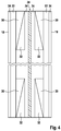
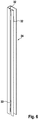
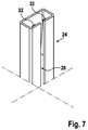
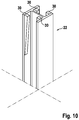
- FIGS. 3 to 10 show details of the coupling by means of a coupling system 14. More specifically, the FIG. 3 the detail of FIG. 1 (turned 90 degrees). It can be seen clearly that in each of the adjacent side walls 18 made of concrete, in each case a C-section 24 made of steel is embedded to form the guide grooves 20, which extends vertically in the respective side wall 18 and is arranged with its longitudinal slot 26 so that this communicating with the outside. Head studs 28, which are welded to the C-profile 24, engage in the side wall 18 of the respective floating pontoon 12 and transmit any forces from the steel connection in the respective side wall 18th
- a coupling carrier 22 in the form of a double-T-carrier is inserted or inserted into the paired opposite guide grooves 20.
- results are at the upper and lower ends of the coupling support 22 on the inner sides of the crossbar respective in the longitudinal direction of the coupling carrier 22 over a certain length of the coupling member 22 extending wedges 30 applied to form a respective wedge-shaped surface, for example by welding.
- the ramped surface of the wedges 30 rises toward the upper end of the coupling carrier 22.
- each of the two inner sides has a pair of offending wedges 30 thereof, the pair being offset from the opposite pair of wedges 30 on the opposite inner side of the coupling carrier 22, transverse to the longitudinal extent of the coupling carrier 22.
- wedges 32 on the inside of the respective C-profile 24 at corresponding to the wedges 30 of the coupling carrier 22 wedges 32 for forming a wedge-shaped surface, for example Welding attached.
- the wedges 32 extend in the longitudinal direction of the C-profiles 24 over a partial length thereof, but have a ramp-shaped surface complementary to the wedges 30.
- Each pair of oppositely disposed wedges 30 and 32 forms so-called double wedges.
- At the lower end of the coupling carrier 22 wedges 30 are also applied. Their ramp-shaped surface, however, falls off towards the lower end.
- 24 complementary wedges 32 are attached to the lower end of the C-profile.
- the coupling carrier 22 are inserted or inserted from above into the respective paired guide grooves 20 of adjacent floating pontoons 12, the floating pontoons 12 are pressed against each other and the respective coupling carrier 22 is fixed.
- the oppositely disposed wedges 30 and 32 are used for better fixation and to bring the floating pontoons 12 during the assembly process in the correct position.
- spacers 34 may be arranged, for example, neoprene. These spacers 34 may be mounted on the outsides of the floating pontoons even before the floating pontoons 12 are launched. They serve that in the case in which a potting material, such as grout, is to be filled in the space 36 in a respective guide groove 20 between the same and an inserted coupling carrier 22, the potting material does not swell.
- a foot plate 38 at the lower end of the C-profile 24 also fulfills this purpose. Normally, the coupling carrier 22 is not supported on the base plate 38.
Landscapes
- Chemical & Material Sciences (AREA)
- Engineering & Computer Science (AREA)
- Combustion & Propulsion (AREA)
- Mechanical Engineering (AREA)
- Ocean & Marine Engineering (AREA)
- Bridges Or Land Bridges (AREA)
Applications Claiming Priority (2)
| Application Number | Priority Date | Filing Date | Title |
|---|---|---|---|
| DE102015108777 | 2015-06-03 | ||
| DE102015016819.3A DE102015016819A1 (de) | 2015-06-03 | 2015-12-22 | Schwimmkörper zur Bildung einer Pontonanlage als Fundament zur Aufnahme von Plattformen etc., Kopplungssystem zur Kopplung von derartigen Schwimmkörpern, Pontonanlage aus derartigen Schwimmkörpern und Verfahren zum Koppeln derartiger Schwimmkörper |
Publications (1)
| Publication Number | Publication Date |
|---|---|
| EP3100943A1 true EP3100943A1 (fr) | 2016-12-07 |
Family
ID=55970827
Family Applications (1)
| Application Number | Title | Priority Date | Filing Date |
|---|---|---|---|
| EP16168838.7A Withdrawn EP3100943A1 (fr) | 2015-06-03 | 2016-05-10 | Flotteurs destines a former un ponton en tant que fondation destinee a recevoir des plateformes, etc., systeme de couplage de tels flotteurs, installation de ponton a partir de tels flotteurs et procede de couplage de tels flotteurs |
Country Status (1)
| Country | Link |
|---|---|
| EP (1) | EP3100943A1 (fr) |
Cited By (3)
| Publication number | Priority date | Publication date | Assignee | Title |
|---|---|---|---|---|
| WO2021054836A1 (fr) * | 2019-09-16 | 2021-03-25 | Pontemar As | Construction de pont flottant |
| EP3828073A1 (fr) * | 2019-11-29 | 2021-06-02 | A-Laiturit Oy | Module flottant et structure flottante |
| CZ309234B6 (cs) * | 2021-04-08 | 2022-06-08 | Lodě Helios s.r.o. | Spojovací zařízení |
Citations (7)
| Publication number | Priority date | Publication date | Assignee | Title |
|---|---|---|---|---|
| FR2335717A1 (fr) * | 1975-12-19 | 1977-07-15 | Breheret Et Cie Sarl Ateliers | Dispositif de jonction de pontons et d'elements flottants similaires |
| GB2248904A (en) * | 1990-10-17 | 1992-04-22 | Patrick Myles Johnson | A linkable fender |
| DE9414441U1 (de) * | 1994-09-06 | 1995-04-06 | Pfeiffer, Franziska, 85551 Kirchheim | Langgestreckter Schwimmkörper |
| WO2006116854A1 (fr) * | 2005-05-04 | 2006-11-09 | Duane Whybourne | Systeme de quai flottant |
| DE202009016987U1 (de) | 2009-12-16 | 2011-04-28 | Ritscher, Klas | Kupplungssystem zum Verbinden von Schwimmkörpern |
| EP2457820A2 (fr) * | 2010-11-24 | 2012-05-30 | Mid-America Foundation Supply Inc. | Poussoir amélioré de barge |
| US8608407B1 (en) * | 2010-07-15 | 2013-12-17 | Hydrohoist Marine Group, Inc. | Top-lock connector for a floating dock |
-
2016
- 2016-05-10 EP EP16168838.7A patent/EP3100943A1/fr not_active Withdrawn
Patent Citations (7)
| Publication number | Priority date | Publication date | Assignee | Title |
|---|---|---|---|---|
| FR2335717A1 (fr) * | 1975-12-19 | 1977-07-15 | Breheret Et Cie Sarl Ateliers | Dispositif de jonction de pontons et d'elements flottants similaires |
| GB2248904A (en) * | 1990-10-17 | 1992-04-22 | Patrick Myles Johnson | A linkable fender |
| DE9414441U1 (de) * | 1994-09-06 | 1995-04-06 | Pfeiffer, Franziska, 85551 Kirchheim | Langgestreckter Schwimmkörper |
| WO2006116854A1 (fr) * | 2005-05-04 | 2006-11-09 | Duane Whybourne | Systeme de quai flottant |
| DE202009016987U1 (de) | 2009-12-16 | 2011-04-28 | Ritscher, Klas | Kupplungssystem zum Verbinden von Schwimmkörpern |
| US8608407B1 (en) * | 2010-07-15 | 2013-12-17 | Hydrohoist Marine Group, Inc. | Top-lock connector for a floating dock |
| EP2457820A2 (fr) * | 2010-11-24 | 2012-05-30 | Mid-America Foundation Supply Inc. | Poussoir amélioré de barge |
Cited By (5)
| Publication number | Priority date | Publication date | Assignee | Title |
|---|---|---|---|---|
| WO2021054836A1 (fr) * | 2019-09-16 | 2021-03-25 | Pontemar As | Construction de pont flottant |
| EP3828073A1 (fr) * | 2019-11-29 | 2021-06-02 | A-Laiturit Oy | Module flottant et structure flottante |
| EP4219284A1 (fr) * | 2019-11-29 | 2023-08-02 | A-Laiturit Oy | Module flottant et structure flottante |
| CZ309234B6 (cs) * | 2021-04-08 | 2022-06-08 | Lodě Helios s.r.o. | Spojovací zařízení |
| WO2022214115A1 (fr) * | 2021-04-08 | 2022-10-13 | Lodě Helios s.r.o. | Dispositif de couplage |
Similar Documents
| Publication | Publication Date | Title |
|---|---|---|
| DE2755833A1 (de) | Element fuer boeschungsabfangungen | |
| EP0163292A2 (fr) | Barrage pour la protection contre les crues | |
| DE102014107323A1 (de) | Kranträger für einen Kran, insbesondere für einen Brücken- oder Portalkran, und einen Kran hiermit | |
| DE2302053B2 (de) | Vertäuvorrichtung für einen Leitungsgraben o.dgl. mit abgestuftem Querschnitt | |
| DE3523357C2 (fr) | ||
| EP2264323A2 (fr) | Connecteur à fiches | |
| EP1658405B1 (fr) | Element de coffrage isolant notamment destine a la fabrication du coffrage d'une dalle de plancher d'un immeuble et procede de fabrication d'un tel coffrage | |
| EP1902186B1 (fr) | Dispositif d'assemblage | |
| DE2725742C2 (de) | Aus plattenförmigen Deckenelementen aufgebaute Decke | |
| DE2128957A1 (fr) | ||
| DE2304223A1 (de) | Bauelement | |
| DE2624954C2 (de) | Doppelwandige Stahlverbauplatte | |
| DE102015016819A1 (de) | Schwimmkörper zur Bildung einer Pontonanlage als Fundament zur Aufnahme von Plattformen etc., Kopplungssystem zur Kopplung von derartigen Schwimmkörpern, Pontonanlage aus derartigen Schwimmkörpern und Verfahren zum Koppeln derartiger Schwimmkörper | |
| DE2206973A1 (de) | Raeumliches bauelement zur bildung von trag- und stuetzwerken aller art | |
| DE102005019034B4 (de) | Verbauvorrichtung | |
| DE102014108274B4 (de) | Hochwasser-Schutzsystem | |
| DE2551507A1 (de) | Mauerverbund | |
| WO2017089605A1 (fr) | Plateforme modulaire | |
| DE4021937C1 (en) | Load distributing platform for groove support legs - has continuous parallel struts with several pressure or tensile supports in between | |
| EP1960611B1 (fr) | Element de construction en bois destine au montage de parois de batiments | |
| EP1101883A1 (fr) | Dispositif pour la réalisation d'un raccordement d'armatures entre un élément de construction en béton et un élément de construction connecté | |
| EP1936054B9 (fr) | Languette de traction destinée à la fixation de plaques murales en béton poreux, ainsi que système de plaques murales en béton poreux doté de languettes de traction | |
| DE2905238A1 (de) | Unterkonstruktion | |
| AT396701B (de) | Ankerkeilplatte und verfahren zum trockenlegen von mauern unter verwendung solcher platten | |
| DE3403745C2 (fr) |
Legal Events
| Date | Code | Title | Description |
|---|---|---|---|
| PUAI | Public reference made under article 153(3) epc to a published international application that has entered the european phase |
Free format text: ORIGINAL CODE: 0009012 |
|
| 17P | Request for examination filed |
Effective date: 20160510 |
|
| AK | Designated contracting states |
Kind code of ref document: A1 Designated state(s): AL AT BE BG CH CY CZ DE DK EE ES FI FR GB GR HR HU IE IS IT LI LT LU LV MC MK MT NL NO PL PT RO RS SE SI SK SM TR |
|
| AX | Request for extension of the european patent |
Extension state: BA ME |
|
| 17Q | First examination report despatched |
Effective date: 20161130 |
|
| STAA | Information on the status of an ep patent application or granted ep patent |
Free format text: STATUS: THE APPLICATION IS DEEMED TO BE WITHDRAWN |
|
| 18D | Application deemed to be withdrawn |
Effective date: 20190326 |