EP3101190B1 - Module de paroi de séparation d'une paroi de séparation - Google Patents
Module de paroi de séparation d'une paroi de séparation Download PDFInfo
- Publication number
- EP3101190B1 EP3101190B1 EP16172296.2A EP16172296A EP3101190B1 EP 3101190 B1 EP3101190 B1 EP 3101190B1 EP 16172296 A EP16172296 A EP 16172296A EP 3101190 B1 EP3101190 B1 EP 3101190B1
- Authority
- EP
- European Patent Office
- Prior art keywords
- vertical
- profile
- profiles
- module
- horizontal
- Prior art date
- Legal status (The legal status is an assumption and is not a legal conclusion. Google has not performed a legal analysis and makes no representation as to the accuracy of the status listed.)
- Not-in-force
Links
- 238000005192 partition Methods 0.000 title description 53
- 238000007789 sealing Methods 0.000 claims description 19
- 239000000725 suspension Substances 0.000 claims description 12
- 238000005452 bending Methods 0.000 claims description 11
- 230000000087 stabilizing effect Effects 0.000 claims description 3
- 238000000638 solvent extraction Methods 0.000 claims 8
- 210000001331 nose Anatomy 0.000 claims 2
- 230000002093 peripheral effect Effects 0.000 claims 2
- 230000013011 mating Effects 0.000 description 26
- 238000003780 insertion Methods 0.000 description 6
- 230000037431 insertion Effects 0.000 description 6
- 230000007246 mechanism Effects 0.000 description 5
- 230000008901 benefit Effects 0.000 description 4
- 238000009434 installation Methods 0.000 description 4
- 230000009471 action Effects 0.000 description 3
- 230000015572 biosynthetic process Effects 0.000 description 3
- 238000010276 construction Methods 0.000 description 3
- 238000004519 manufacturing process Methods 0.000 description 3
- 238000000034 method Methods 0.000 description 3
- 230000009467 reduction Effects 0.000 description 3
- 230000002730 additional effect Effects 0.000 description 2
- 230000006978 adaptation Effects 0.000 description 1
- 230000000295 complement effect Effects 0.000 description 1
- 238000005520 cutting process Methods 0.000 description 1
- 238000006073 displacement reaction Methods 0.000 description 1
- 238000009413 insulation Methods 0.000 description 1
- 230000003993 interaction Effects 0.000 description 1
- 239000002184 metal Substances 0.000 description 1
- 238000004080 punching Methods 0.000 description 1
- 230000002787 reinforcement Effects 0.000 description 1
- 230000006641 stabilisation Effects 0.000 description 1
- 238000011105 stabilization Methods 0.000 description 1
- 230000003068 static effect Effects 0.000 description 1
- 238000003860 storage Methods 0.000 description 1
- 238000003466 welding Methods 0.000 description 1
Images


Classifications
-
- E—FIXED CONSTRUCTIONS
- E04—BUILDING
- E04B—GENERAL BUILDING CONSTRUCTIONS; WALLS, e.g. PARTITIONS; ROOFS; FLOORS; CEILINGS; INSULATION OR OTHER PROTECTION OF BUILDINGS
- E04B2/00—Walls, e.g. partitions, for buildings; Wall construction with regard to insulation; Connections specially adapted to walls
- E04B2/74—Removable non-load-bearing partitions; Partitions with a free upper edge
- E04B2/7407—Removable non-load-bearing partitions; Partitions with a free upper edge assembled using frames with infill panels or coverings only; made-up of panels and a support structure incorporating posts
-
- E—FIXED CONSTRUCTIONS
- E04—BUILDING
- E04B—GENERAL BUILDING CONSTRUCTIONS; WALLS, e.g. PARTITIONS; ROOFS; FLOORS; CEILINGS; INSULATION OR OTHER PROTECTION OF BUILDINGS
- E04B2/00—Walls, e.g. partitions, for buildings; Wall construction with regard to insulation; Connections specially adapted to walls
- E04B2/74—Removable non-load-bearing partitions; Partitions with a free upper edge
- E04B2/7407—Removable non-load-bearing partitions; Partitions with a free upper edge assembled using frames with infill panels or coverings only; made-up of panels and a support structure incorporating posts
- E04B2/7416—Removable non-load-bearing partitions; Partitions with a free upper edge assembled using frames with infill panels or coverings only; made-up of panels and a support structure incorporating posts with free upper edge, e.g. for use as office space dividers
- E04B2/7422—Removable non-load-bearing partitions; Partitions with a free upper edge assembled using frames with infill panels or coverings only; made-up of panels and a support structure incorporating posts with free upper edge, e.g. for use as office space dividers with separate framed panels without intermediary support posts
-
- E—FIXED CONSTRUCTIONS
- E04—BUILDING
- E04B—GENERAL BUILDING CONSTRUCTIONS; WALLS, e.g. PARTITIONS; ROOFS; FLOORS; CEILINGS; INSULATION OR OTHER PROTECTION OF BUILDINGS
- E04B2/00—Walls, e.g. partitions, for buildings; Wall construction with regard to insulation; Connections specially adapted to walls
- E04B2/74—Removable non-load-bearing partitions; Partitions with a free upper edge
- E04B2/76—Removable non-load-bearing partitions; Partitions with a free upper edge with framework or posts of metal
- E04B2/78—Removable non-load-bearing partitions; Partitions with a free upper edge with framework or posts of metal characterised by special cross-section of the frame members as far as important for securing wall panels to a framework with or without the help of cover-strips
- E04B2/7854—Removable non-load-bearing partitions; Partitions with a free upper edge with framework or posts of metal characterised by special cross-section of the frame members as far as important for securing wall panels to a framework with or without the help of cover-strips of open profile
- E04B2/789—Removable non-load-bearing partitions; Partitions with a free upper edge with framework or posts of metal characterised by special cross-section of the frame members as far as important for securing wall panels to a framework with or without the help of cover-strips of open profile of substantially U- or C- section
-
- E—FIXED CONSTRUCTIONS
- E04—BUILDING
- E04B—GENERAL BUILDING CONSTRUCTIONS; WALLS, e.g. PARTITIONS; ROOFS; FLOORS; CEILINGS; INSULATION OR OTHER PROTECTION OF BUILDINGS
- E04B2/00—Walls, e.g. partitions, for buildings; Wall construction with regard to insulation; Connections specially adapted to walls
- E04B2/74—Removable non-load-bearing partitions; Partitions with a free upper edge
- E04B2/82—Removable non-load-bearing partitions; Partitions with a free upper edge characterised by the manner in which edges are connected to the building; Means therefor; Special details of easily-removable partitions as far as related to the connection with other parts of the building
- E04B2/821—Connections between two opposed surfaces (i.e. floor and ceiling) by means of a device offering a restraining force acting in the plane of the partition
- E04B2/822—Elastic connections, e.g. inflated joints
-
- E—FIXED CONSTRUCTIONS
- E04—BUILDING
- E04B—GENERAL BUILDING CONSTRUCTIONS; WALLS, e.g. PARTITIONS; ROOFS; FLOORS; CEILINGS; INSULATION OR OTHER PROTECTION OF BUILDINGS
- E04B2/00—Walls, e.g. partitions, for buildings; Wall construction with regard to insulation; Connections specially adapted to walls
- E04B2/74—Removable non-load-bearing partitions; Partitions with a free upper edge
- E04B2/82—Removable non-load-bearing partitions; Partitions with a free upper edge characterised by the manner in which edges are connected to the building; Means therefor; Special details of easily-removable partitions as far as related to the connection with other parts of the building
- E04B2/821—Connections between two opposed surfaces (i.e. floor and ceiling) by means of a device offering a restraining force acting in the plane of the partition
- E04B2/824—Connections between two opposed surfaces (i.e. floor and ceiling) by means of a device offering a restraining force acting in the plane of the partition restrained elastically at one surface and inelastically at the opposing surface
-
- E—FIXED CONSTRUCTIONS
- E04—BUILDING
- E04B—GENERAL BUILDING CONSTRUCTIONS; WALLS, e.g. PARTITIONS; ROOFS; FLOORS; CEILINGS; INSULATION OR OTHER PROTECTION OF BUILDINGS
- E04B2/00—Walls, e.g. partitions, for buildings; Wall construction with regard to insulation; Connections specially adapted to walls
- E04B2/74—Removable non-load-bearing partitions; Partitions with a free upper edge
- E04B2/82—Removable non-load-bearing partitions; Partitions with a free upper edge characterised by the manner in which edges are connected to the building; Means therefor; Special details of easily-removable partitions as far as related to the connection with other parts of the building
- E04B2/827—Partitions constituted of sliding panels
-
- E—FIXED CONSTRUCTIONS
- E04—BUILDING
- E04B—GENERAL BUILDING CONSTRUCTIONS; WALLS, e.g. PARTITIONS; ROOFS; FLOORS; CEILINGS; INSULATION OR OTHER PROTECTION OF BUILDINGS
- E04B2/00—Walls, e.g. partitions, for buildings; Wall construction with regard to insulation; Connections specially adapted to walls
- E04B2/74—Removable non-load-bearing partitions; Partitions with a free upper edge
- E04B2/82—Removable non-load-bearing partitions; Partitions with a free upper edge characterised by the manner in which edges are connected to the building; Means therefor; Special details of easily-removable partitions as far as related to the connection with other parts of the building
- E04B2/828—Connections between partitions and structural walls
Definitions
- the present invention relates to a partition wall module of a partition wall for covering an opening in a building and a method for the assembly of a partition wall module according to the present invention.
- partition walls are usually made available as mobile partition wall systems in order to be able to separate corresponding smaller units in a large room with the aid of individual partition wall modules.
- these smaller units are not only visually but also acoustically separated or decoupled from one another.
- the known partition wall modules are made available in a standardized manner for this purpose and are produced in a uniform manner.
- Such partition wall modules are usually equipped with a module frame, which is provided with cover plates on both sides. Of course, additional insulation for better acoustic decoupling can also be made available between the cover plates, that is, within the module frame.
- a wall element with a frame which consists of longitudinal beams and cross members.
- the cross members have tabs which can be passed through slots in the longitudinal members and folded over for fastening.
- the DE 10 2013 014 600 A1 discloses a partition wall module with a frame made up of two longitudinal members and several cross members, in which roller systems are arranged on two upper cross members. The exact positioning of the roller systems on the cross members is very complex and leads to an increased installation effort.
- a partition wall module for a partition wall for covering an opening in a structure.
- the partition module has a module frame made of at least two vertical profiles and at least two horizontal profiles.
- a cover plate is attached to the module frame on both sides.
- a partition wall module according to the invention is characterized in that the horizontal profiles have a contact section at each end, which is in at least partially form-locking contact with a mating contact section of a vertical profile for fastening the horizontal profiles to the vertical profiles.
- a separating profile has a known basic structure.
- a module frame is also provided here, which defines a frame structure in order to be able to ensure a corresponding fastening of the cover plate.
- vertical profiles and horizontal profiles are provided in order to build up the module frame.
- the terminology of the vertical profile relates to a vertical arrangement of the vertical profile in the installation situation.
- the terminology of the horizontal profile relates to an installation situation of the horizontal profile in a horizontal orientation.
- the module frame is preferably constructed in such a way that the vertical profiles with the horizontal profiles are essentially at right angles to one another after their connection in the installation situation.
- each of the horizontal profiles is equipped with a contact section at the respective end. Since the horizontal profiles, just like the vertical profiles, are usually designed with a corresponding longitudinal extension, they have two ends with a correspondingly two contact sections in total. The same applies to the vertical profiles, which also have a mating contact section at least at the respective end.
- the invention now provides for the correlation of contact sections and mating contact sections. These correlate in such a way that they make the fastening contact for the fastening horizontal profiles on the vertical profiles at least in sections Provide form-fitting training contact.
- This form-fitting contact can be produced in the most varied of ways. For example, plugging the contact section and the mating contact section into one another, at least in sections, can provide this desired form fit for the fastening. Of course, an additional action can also develop or reinforce this form fit.
- One possible solution for this is if, for example, the contact section is designed in the form of a tab and is inserted into a corresponding tab slot of the mating contact section.
- This insertion already provides the form fit for fastening, at least in sections.
- a plastic deformation of the contact section in the form of the tab is now possible, for example, in order to be able to achieve an even further improved form fit and thus greater stability of the module frame in this way.
- the contact section or the mating contact section has a corresponding design.
- the decisive factor here is the interaction of the two components, that is to say the contact section and the mating contact section, so that in this way the at least partially form-fitting fastening functionality is provided.
- every description of a correlation between contact element and mating contact element also applies in reverse, so that the kinematic reversal naturally includes the same functionality within the scope of the scope of protection of the present application.
- this relates to the strength of the partition wall module, so that a reduction in the thickness of the module frame can be followed by a reduction in the thickness of the partition wall module.
- the reduction in the geometric dimensions and weight also means that the new partition modules according to the invention can be transported in an increased load.
- the contact sections of all horizontal profiles are identical to one another and / or the mating contact sections of all vertical profiles are designed to be identical to one another.
- the vertical profiles and / or Horizontal profiles can be used in an identical manner in this way in both orientations.
- all contact sections can be brought with all mating contact sections in the contact according to the invention which is at least partially fastened in a form-fitting manner. This further enhances the usability of the correlation between different horizontal profiles and different vertical profiles.
- not only the mating contact sections and the contact sections, but also all horizontal profiles or all vertical profiles are designed to be identical or essentially identical. However, differences can exist in particular with regard to the longitudinal extension and thus the geometric dimensions of the horizontal profiles or the vertical profiles.
- the contact sections are designed as contact tabs which extend through the mating contact sections in the form of tab slots in order to form a section-wise form fit for fastening.
- a tab is in particular a flat, elongated extension with a flat top and a flat bottom.
- a corresponding tab slot forms a complementary contour for this tab, so that the tab can be inserted into the tab slot with as little play as possible around the tab. In particular, this is a loose fit that provides the desired form fit as a plug connection.
- this section-wise form fit can be improved even further in terms of stability by the insertion and then by an action, for example plastic deformation will.
- the formation of the contact sections or the mating contact sections is possible, for example, by sheet metal cutting or punching.
- At least one of the contact sections has a bending area which forms the securing form fit through plastic deformation.
- the bending area is arranged between the end section of the contact section and the base body of the horizontal profile, in particular with a reduced cross section. If a force is now applied in a tab slot, for example after insertion in accordance with the preceding paragraph, plastic deformation can take place within the bending area.
- the action of bending over is given on the basis of a rotational movement, so that part of the contact section is bent upwards while another part of the contact section is bent downwards at the same time.
- each vertical profile has at least two vertical telescopic sections which overlap one another in the direction of longitudinal extension of the vertical profile, the The length of the overlap is made variable. For example, U-profiles can then be pushed into one another in the vertical profile in order to form the vertical telescopic sections in this way.
- the longitudinal extension of the vertical profiles can be adapted in this way.
- the cover plates can also be cut to length in order to be able to carry out the desired adaptation for the partition module even on site on the construction site.
- additional fastening means can be provided in order to connect the individual vertical telescopic sections to one another in the desired relative longitudinal position.
- the correlation of different mating contact sections of the vertical profiles is used to automatically fix the vertical telescopic sections relative to one another by inserting the contact sections.
- corresponding mating contact sections of the individual vertical telescopic sections overlap in different correlations with one another, so that a functional union can be achieved here.
- a third horizontal profile is arranged between an upper horizontal profile, which forms an upper end of the module frame, and a lower horizontal profile, which forms the lower end of the module frame, and is attached to the vertical profiles to stabilize the module frame is.
- the module frame can basically be a simple rectangle
- the provision of a third and centrally arranged horizontal profile further increases the stability.
- the central horizontal profile can have a parallel or essentially parallel alignment, and in particular be designed identically or essentially identical to the other two horizontal profiles with regard to its geometric extension.
- an inclined and thus inclined alignment of the central horizontal profile provides an even stronger stabilizing effect for the module frame.
- a mounting interface can also be provided in the central horizontal profile in order to be able to fasten or store mechanical units in the form of an adjusting mechanism, for example.
- an adjustment mechanism can bring advantages if, for example, sealing lips are to be mounted variably in a retracted position and an extended position.
- a partition module In the case of a partition module according to the invention, at least three bearing interfaces for the attachment of suspension devices for the movable suspension of the partition module on a ceiling of the building are formed in the upper horizontal profile. Usually one or two of these bearing interfaces are actually used. In particular, in the case of heavy embodiments of a partition wall module, it may be necessary that a suspension device is attached to each of two bearing interfaces. In this way, a simple and, above all, little friction displacement functionality can be provided for the partition module in associated running rails. Alternatively, however, suspension with a single suspension device is also conceivable in the same technical embodiment of the module frame.
- This is designed in particular as a central suspension, so that the partition wall module can be positioned transversely during suspension due to the corresponding central arrangement of the third bearing interface.
- This is in particular for a particularly simple and inexpensive training of the rail system is advantageous in terms of the storage position of the partition module in the rail system.
- These individual bearing interfaces can be designed as holes, preferably also as elongated holes, in order to be able to additionally provide a corresponding fine adjustment of the relative positioning of the individual suspension devices.
- At least the upper horizontal profile has a profile nose into which the cover plate is suspended by means of hook devices.
- This profile nose can, for example, be a locking projection or a section from a corresponding U-profile.
- the hook device of the cover plate can, for example, be an inverted U-profile in order to be hooked into the associated profile nose in a correspondingly simple, inexpensive and fast manner.
- a self-stabilizing arrangement can be achieved in this way due to the weight of the cover plate.
- the cover plate can additionally have plastic strips which, after being hung in the profile nose, provide a corresponding contact to the module frame and are in particular designed in an acoustically decoupling manner.
- the vertical profiles have a locking element for engaging locking lugs of vertical sealing strips for fastening these vertical sealing strips to the vertical profiles.
- these latching elements are designed along the entire length of the vertical profiles.
- the respective sealing strip can be attached.
- These sealing strips can in particular be provided with magnetic strips in order to be able to establish an even better connection with the adjacent partition module according to the tongue and groove.
- the aim of these sealing strips is to acoustically decouple the two separate room areas in one building.
- a horizontal sealing lip is arranged in each case on an upper horizontal profile and a lower horizontal profile, in particular in an extendable manner, for sealing the partition module against the ceiling and / or the floor of the building.
- the sealing lips are now pressed upwards against the ceiling and downwards against the floor of the structure in order to further improve the acoustic decoupling of the two separate room sections in addition to a stabilizing effect of the partition module.
- the method has the same advantages as have been explained in detail with reference to a partition wall module according to the invention.
- the steps of hanging the cover plates can also be provided.
- the order in which the fastening contact is made are essentially free. In this way, the vertical profile can already be connected completely on the first side, and then the connection to the second vertical profile is made available on the second side. All the insertion steps between contact sections and mating contact sections can also be completed first, in order to be able to complete the final action, for example bending over the individual contact sections around bending areas.
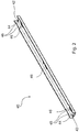
- a vertical profile 30 is made available, so that a total of three horizontal profiles 40 according to FIG Fig. 2 with tab-shaped contact sections 42 can be plugged into associated tab slots as mating contact sections 32.
- a corresponding form-fitting and thus securing contact between the contact sections 42 and the mating contact sections 32 is already formed here by the insertion.
- a second vertical profile 30 is arranged in the same way at the opposite end of the horizontal profiles 40, so that finally, in particular by additionally bending the individual contact sections 42 around a bending area 44, a further reinforcement of the form-fitting fastening situation can be achieved.
- a sealing lip 80 is now attached to the top and the bottom of the module frame 20, which in these embodiments is designed to be retractable and extendable with the aid of a scissor mechanism.
- Sealing strips 70 are then latched onto the two vertical profiles 30 via associated latching lugs 72 in corresponding latching elements 36 of the vertical profiles 30.
- These are tongue-and-groove systems in order to be able to provide the best possible acoustic seal even in a vertical alignment of the partition module 10.
- cover plates 50 can be hung on both sides, in particular a corresponding hook device 52 in associated profile lugs 48 according to FIG Fig. 2 be hung. This hanging is simple, quick and inexpensive and the stabilization takes place in particular through the weight of the cover plate 50.
Landscapes
- Engineering & Computer Science (AREA)
- Architecture (AREA)
- Physics & Mathematics (AREA)
- Electromagnetism (AREA)
- Civil Engineering (AREA)
- Structural Engineering (AREA)
- Building Environments (AREA)
- Specific Sealing Or Ventilating Devices For Doors And Windows (AREA)
Claims (7)
- Module de paroi de séparation (10) d'une paroi de séparation pour couvrir une ouverture dans un corps de bâtiment, comprenant un cadre de module (20) fait au moins de deux profils verticaux (30) et au moins de deux profils horizontaux (40), une plaque de recouvrement (50) respective étant attachée au cadre de module (20) des deux côtés, une lèvre d'étanchéité (80) horizontale respective étant agencée de manière extensible sur un profil supérieur horizontal (40) et sur un profil inférieur horizontal (40) pour une étanchéification du module de paroi de séparation (10) vers le plafond et/ou le plancher du corps de bâtiment, caractérisé en ce que les profils horizontaux (40) présentent une section de contact (42) à chaque extrémité, laquelle section est en contact attachant par la forme au moins par sections avec une contre-section de contact (32) d'un profil vertical (30) pour attacher les profils horizontaux (40) sur les profils verticaux (30), et en ce qu'au moins trois interfaces de support (46) sont aménagées dans le profil horizontal supérieur (40) pour attacher des dispositifs de suspension (60) pour la suspension mobile du module de paroi de séparation (10) sur un plafond du corps de bâtiment, et en ce qu'au moins le profil horizontal supérieur (40) présente un ergot profilé (48), dans lequel la plaque de recouvrement (50) est accrochée par des dispositifs de crochet (52).
- Module de paroi de séparation (10) selon la revendication 1, caractérisé en ce que les sections de contact (42) de tous les profils horizontaux (40) sont aménagées identiques les unes aux autres et/ou les contre-sections de contact (32) de tous les profils verticaux (30) sont aménagées identiques les unes aux autres.
- Module de paroi de séparation (10) selon l'une des revendications précédentes, caractérisé en ce que les sections de contact (42) sont aménagées comme éclisses de contact, lesquelles passent à travers les contre-sections de contact (32) en forme de fente à éclisse pour établir une liaison par la forme par sections pour l'attachement.
- Module de paroi de séparation (10) selon l'une des revendications précédentes, caractérisé en ce qu'au moins l'une des sections de contact (42) comprend une région de pliage (44), laquelle aménage la liaison attachante par la forme par déformation plastique.
- Module de paroi de séparation (10) selon l'une des revendications précédentes, caractérisé en ce que chaque profil vertical (30) comprend au moins deux sections télescopiques verticales, lesquelles se chevauchent en direction d'extension longitudinale du profil vertical (30), la longueur de chevauchement étant aménagée de façon variable.
- Module de paroi de séparation (10) selon l'une des revendications précédentes, caractérisé en ce que, entre un profil horizontal supérieur (40), lequel établit une terminaison supérieure du cadre de module (20), et un profil horizontal inférieur (40), lequel établit une terminaison inférieure du cadre de module (20), est agencé un troisième profil horizontal (40) et est attaché sur les profils verticaux (30) pour stabiliser le cadre de module (20).
- Module de paroi de séparation (10) selon l'une des revendications précédentes, caractérisé en ce que les profils verticaux (30) présentent un élément d'encastrement (36) pour encastrer des ergots d'encastrement (72) des baguettes d'étanchéité (70) verticales pour attacher ces baguettes d'étanchéité (70) verticales sur les profils verticaux (30).
Applications Claiming Priority (1)
| Application Number | Priority Date | Filing Date | Title |
|---|---|---|---|
| DE102015108660.3A DE102015108660A1 (de) | 2015-06-01 | 2015-06-01 | Trennwandmodul einer Trennwand |
Publications (2)
| Publication Number | Publication Date |
|---|---|
| EP3101190A1 EP3101190A1 (fr) | 2016-12-07 |
| EP3101190B1 true EP3101190B1 (fr) | 2020-11-11 |
Family
ID=56112836
Family Applications (1)
| Application Number | Title | Priority Date | Filing Date |
|---|---|---|---|
| EP16172296.2A Not-in-force EP3101190B1 (fr) | 2015-06-01 | 2016-05-31 | Module de paroi de séparation d'une paroi de séparation |
Country Status (3)
| Country | Link |
|---|---|
| US (1) | US20160348359A1 (fr) |
| EP (1) | EP3101190B1 (fr) |
| DE (1) | DE102015108660A1 (fr) |
Families Citing this family (4)
| Publication number | Priority date | Publication date | Assignee | Title |
|---|---|---|---|---|
| NL2018770B1 (nl) * | 2017-04-24 | 2018-11-05 | Maars Holding Bv | Wandelement voor een scheidingswand en scheidingswand |
| KR102345056B1 (ko) * | 2021-05-13 | 2021-12-29 | 노원훈 | 솔레노이드를 이용한 모듈식 벽체 조립체 |
| CN114439130B (zh) * | 2021-12-24 | 2023-11-14 | 珠海百亚电子科技有限公司 | 一种面板位置可调的模块墙体 |
| CN114439131B (zh) * | 2021-12-24 | 2023-11-14 | 珠海百亚电子科技有限公司 | 一种模块化拼接的模块墙体 |
Citations (2)
| Publication number | Priority date | Publication date | Assignee | Title |
|---|---|---|---|---|
| US20030155083A1 (en) * | 2002-02-15 | 2003-08-21 | Macdonald Douglas B. | Panel system |
| DE10300821A1 (de) * | 2003-01-10 | 2004-07-29 | Dorma Gmbh + Co. Kg | Mobile Trennwand |
Family Cites Families (20)
| Publication number | Priority date | Publication date | Assignee | Title |
|---|---|---|---|---|
| FR1435227A (fr) * | 1965-03-16 | 1966-04-15 | Dispositif d'assemblage et éléments pour l'exécution de panneaux, cloisons et constructions similaires | |
| GB1468190A (en) * | 1973-11-30 | 1977-03-23 | Ekert D | Metal frame member |
| DE2404875C3 (de) * | 1974-02-01 | 1978-05-18 | Fa. Justin Hueppe, 2900 Oldenburg | Raumtrennwand aus versetzbaren starren Wandelementen |
| US4120124A (en) * | 1977-06-21 | 1978-10-17 | Hon Industries Inc. | Movable wall assembly |
| US4245442A (en) * | 1979-07-19 | 1981-01-20 | Durham I Milt | Reusable interior wall and ceiling construction system for buildings |
| US4709517A (en) * | 1986-06-02 | 1987-12-01 | Architectural Wall Systems, Inc. | Floor-to-ceiling wall system |
| NZ235365A (en) * | 1989-09-18 | 1993-08-26 | Logan Units Australia Pty Ltd | Stud and keying element |
| US5746034B1 (en) * | 1994-12-30 | 2000-10-17 | Steelcase Inc | Partition system |
| AUPN720795A0 (en) * | 1995-12-19 | 1996-01-18 | Bhp Steel (Jla) Pty Limited | Assembly of frame components, e.g. rail sections for door frames |
| US6301846B1 (en) * | 1996-12-24 | 2001-10-16 | Steelcase Development Inc. | Knock-down portable partition system |
| DE29722391U1 (de) * | 1997-12-18 | 1998-04-09 | Anita Hohnholt, Herstellung und Handel von Trennanlagen, insbesondere Aluminiumteilen, 36157 Ebersburg | Schallgedämmte bewegliche Trennwand aus mehreren Wandelementen |
| US6408579B1 (en) * | 2000-04-25 | 2002-06-25 | Steelcase Development Corporation | Thin panel beam |
| US6729085B2 (en) * | 2001-02-09 | 2004-05-04 | Herman Miller, Inc. | Wall panel system |
| TW539063U (en) * | 2002-07-01 | 2003-06-21 | Chi-Yi Lin | Improved parts rack structure |
| US7707795B2 (en) * | 2006-11-09 | 2010-05-04 | Haworth, Inc. | Wall panel with gusseted open frame |
| GB2454478B (en) * | 2007-11-07 | 2012-08-15 | Royde & Tucker Ltd | Support frame for a sliding door |
| DE202010015260U1 (de) * | 2010-11-10 | 2011-02-10 | Braun, Erwin | Längenverstellbares Ständerprofil für Leichtbauwände |
| US8875774B1 (en) * | 2012-05-09 | 2014-11-04 | Garrett Flores | Protective apparatus for windows and construction areas |
| CA2881683C (fr) * | 2012-09-17 | 2018-07-24 | Steelcase Inc. | Ensemble de mur de separation du plafond au plancher |
| DE102013014600A1 (de) * | 2013-08-26 | 2015-02-26 | Dreypac Gmbh | Trennwand mit wenigstens einem an wenigstens einer Laufschiene verfahrbaren Wandelement, das wenigstens ein flächiges Seitenteil aufweist |
-
2015
- 2015-06-01 DE DE102015108660.3A patent/DE102015108660A1/de active Pending
-
2016
- 2016-05-31 US US15/169,193 patent/US20160348359A1/en not_active Abandoned
- 2016-05-31 EP EP16172296.2A patent/EP3101190B1/fr not_active Not-in-force
Patent Citations (2)
| Publication number | Priority date | Publication date | Assignee | Title |
|---|---|---|---|---|
| US20030155083A1 (en) * | 2002-02-15 | 2003-08-21 | Macdonald Douglas B. | Panel system |
| DE10300821A1 (de) * | 2003-01-10 | 2004-07-29 | Dorma Gmbh + Co. Kg | Mobile Trennwand |
Also Published As
| Publication number | Publication date |
|---|---|
| EP3101190A1 (fr) | 2016-12-07 |
| US20160348359A1 (en) | 2016-12-01 |
| DE102015108660A1 (de) | 2016-12-01 |
Similar Documents
| Publication | Publication Date | Title |
|---|---|---|
| DE102015121193B4 (de) | Rahmengestell für eine Schaltschrankanordnung | |
| DE2350069A1 (de) | System zur montage von platten | |
| EP1413031A1 (fr) | Structure | |
| DE102007026342A1 (de) | Set aus tafelförmigen Paneelen mit bewegbarem Verriegelungselement | |
| EP0310546A1 (fr) | Disposition variable de cadres de montage | |
| EP3101190A1 (fr) | Module de paroi de separation d'une paroi de separation | |
| DE2149665A1 (de) | Abbaufaehige Zwischenwand | |
| WO2015127924A1 (fr) | Armoire de commande | |
| DE102014006460A1 (de) | Profilleiste und Ständerwerk für eine im Trockenbau herzustellende Wand | |
| DE102005016176A1 (de) | C-Profil und Trennwand mit C-Profil | |
| EP2574702B1 (fr) | Structure de toit ou de mur | |
| DE2814089A1 (de) | Kuehlcontainer | |
| DE1937443A1 (de) | Wand- und Deckenteile zur Bildung von Raeumen | |
| EP0271075B1 (fr) | Profilé de jonction pour panneaux de plafond et de mur | |
| DE202007008901U1 (de) | Profilverbinder und Verkleidung | |
| AT510232B1 (de) | Wandelement | |
| EP2256354A1 (fr) | Arrangement de profilés | |
| DE10250498A1 (de) | Metallschindel-Abdeckung für Dächer oder Fassaden | |
| EP4230818A1 (fr) | Dispositif d'aide au montage, agencement de montage et procédé de montage d'un remplissage sur un dispositif de toiture | |
| DE102006025260B4 (de) | Gehäuse für brandgeschützte Wanddurchführungen in Trennwänden mit gleitendem Deckenanschluß | |
| DE102023116787A1 (de) | Einhängeelement für Ankerplatte eines Seitenunfallschutzes, Ankerplatte für Seitenunfallschutz sowie System aus Ankerplatte und Einhängeelement | |
| EP0213451A2 (fr) | Rail pour une construction de support d'un bardage de mur ou plafond | |
| EP0808959A2 (fr) | Système composite pour constructions avec des panneaux autoportants | |
| DE19948469A1 (de) | Kasten für Rolläden oder dergleichen | |
| DE2523851A1 (de) | Trennwandsystem, insbesondere wandfeldkonstruktion o.dgl. |
Legal Events
| Date | Code | Title | Description |
|---|---|---|---|
| PUAI | Public reference made under article 153(3) epc to a published international application that has entered the european phase |
Free format text: ORIGINAL CODE: 0009012 |
|
| STAA | Information on the status of an ep patent application or granted ep patent |
Free format text: STATUS: THE APPLICATION HAS BEEN PUBLISHED |
|
| AK | Designated contracting states |
Kind code of ref document: A1 Designated state(s): AL AT BE BG CH CY CZ DE DK EE ES FI FR GB GR HR HU IE IS IT LI LT LU LV MC MK MT NL NO PL PT RO RS SE SI SK SM TR |
|
| AX | Request for extension of the european patent |
Extension state: BA ME |
|
| RAP1 | Party data changed (applicant data changed or rights of an application transferred) |
Owner name: DORMAKABA DEUTSCHLAND GMBH |
|
| STAA | Information on the status of an ep patent application or granted ep patent |
Free format text: STATUS: REQUEST FOR EXAMINATION WAS MADE |
|
| 17P | Request for examination filed |
Effective date: 20170607 |
|
| RBV | Designated contracting states (corrected) |
Designated state(s): AL AT BE BG CH CY CZ DE DK EE ES FI FR GB GR HR HU IE IS IT LI LT LU LV MC MK MT NL NO PL PT RO RS SE SI SK SM TR |
|
| STAA | Information on the status of an ep patent application or granted ep patent |
Free format text: STATUS: EXAMINATION IS IN PROGRESS |
|
| 17Q | First examination report despatched |
Effective date: 20190403 |
|
| GRAP | Despatch of communication of intention to grant a patent |
Free format text: ORIGINAL CODE: EPIDOSNIGR1 |
|
| STAA | Information on the status of an ep patent application or granted ep patent |
Free format text: STATUS: GRANT OF PATENT IS INTENDED |
|
| INTG | Intention to grant announced |
Effective date: 20200626 |
|
| GRAS | Grant fee paid |
Free format text: ORIGINAL CODE: EPIDOSNIGR3 |
|
| GRAA | (expected) grant |
Free format text: ORIGINAL CODE: 0009210 |
|
| STAA | Information on the status of an ep patent application or granted ep patent |
Free format text: STATUS: THE PATENT HAS BEEN GRANTED |
|
| AK | Designated contracting states |
Kind code of ref document: B1 Designated state(s): AL AT BE BG CH CY CZ DE DK EE ES FI FR GB GR HR HU IE IS IT LI LT LU LV MC MK MT NL NO PL PT RO RS SE SI SK SM TR |
|
| REG | Reference to a national code |
Ref country code: GB Ref legal event code: FG4D Free format text: NOT ENGLISH |
|
| REG | Reference to a national code |
Ref country code: CH Ref legal event code: EP |
|
| REG | Reference to a national code |
Ref country code: AT Ref legal event code: REF Ref document number: 1333606 Country of ref document: AT Kind code of ref document: T Effective date: 20201115 |
|
| REG | Reference to a national code |
Ref country code: DE Ref legal event code: R096 Ref document number: 502016011652 Country of ref document: DE |
|
| REG | Reference to a national code |
Ref country code: IE Ref legal event code: FG4D Free format text: LANGUAGE OF EP DOCUMENT: GERMAN |
|
| REG | Reference to a national code |
Ref country code: CH Ref legal event code: NV Representative=s name: FREI PATENTANWALTSBUERO AG, CH |
|
| REG | Reference to a national code |
Ref country code: NL Ref legal event code: MP Effective date: 20201111 |
|
| PG25 | Lapsed in a contracting state [announced via postgrant information from national office to epo] |
Ref country code: GR Free format text: LAPSE BECAUSE OF FAILURE TO SUBMIT A TRANSLATION OF THE DESCRIPTION OR TO PAY THE FEE WITHIN THE PRESCRIBED TIME-LIMIT Effective date: 20210212 Ref country code: FI Free format text: LAPSE BECAUSE OF FAILURE TO SUBMIT A TRANSLATION OF THE DESCRIPTION OR TO PAY THE FEE WITHIN THE PRESCRIBED TIME-LIMIT Effective date: 20201111 Ref country code: PT Free format text: LAPSE BECAUSE OF FAILURE TO SUBMIT A TRANSLATION OF THE DESCRIPTION OR TO PAY THE FEE WITHIN THE PRESCRIBED TIME-LIMIT Effective date: 20210311 Ref country code: RS Free format text: LAPSE BECAUSE OF FAILURE TO SUBMIT A TRANSLATION OF THE DESCRIPTION OR TO PAY THE FEE WITHIN THE PRESCRIBED TIME-LIMIT Effective date: 20201111 Ref country code: NO Free format text: LAPSE BECAUSE OF FAILURE TO SUBMIT A TRANSLATION OF THE DESCRIPTION OR TO PAY THE FEE WITHIN THE PRESCRIBED TIME-LIMIT Effective date: 20210211 |
|
| PG25 | Lapsed in a contracting state [announced via postgrant information from national office to epo] |
Ref country code: BG Free format text: LAPSE BECAUSE OF FAILURE TO SUBMIT A TRANSLATION OF THE DESCRIPTION OR TO PAY THE FEE WITHIN THE PRESCRIBED TIME-LIMIT Effective date: 20210211 Ref country code: SE Free format text: LAPSE BECAUSE OF FAILURE TO SUBMIT A TRANSLATION OF THE DESCRIPTION OR TO PAY THE FEE WITHIN THE PRESCRIBED TIME-LIMIT Effective date: 20201111 Ref country code: IS Free format text: LAPSE BECAUSE OF FAILURE TO SUBMIT A TRANSLATION OF THE DESCRIPTION OR TO PAY THE FEE WITHIN THE PRESCRIBED TIME-LIMIT Effective date: 20210311 Ref country code: LV Free format text: LAPSE BECAUSE OF FAILURE TO SUBMIT A TRANSLATION OF THE DESCRIPTION OR TO PAY THE FEE WITHIN THE PRESCRIBED TIME-LIMIT Effective date: 20201111 Ref country code: PL Free format text: LAPSE BECAUSE OF FAILURE TO SUBMIT A TRANSLATION OF THE DESCRIPTION OR TO PAY THE FEE WITHIN THE PRESCRIBED TIME-LIMIT Effective date: 20201111 |
|
| REG | Reference to a national code |
Ref country code: LT Ref legal event code: MG9D |
|
| PG25 | Lapsed in a contracting state [announced via postgrant information from national office to epo] |
Ref country code: HR Free format text: LAPSE BECAUSE OF FAILURE TO SUBMIT A TRANSLATION OF THE DESCRIPTION OR TO PAY THE FEE WITHIN THE PRESCRIBED TIME-LIMIT Effective date: 20201111 |
|
| PG25 | Lapsed in a contracting state [announced via postgrant information from national office to epo] |
Ref country code: SK Free format text: LAPSE BECAUSE OF FAILURE TO SUBMIT A TRANSLATION OF THE DESCRIPTION OR TO PAY THE FEE WITHIN THE PRESCRIBED TIME-LIMIT Effective date: 20201111 Ref country code: RO Free format text: LAPSE BECAUSE OF FAILURE TO SUBMIT A TRANSLATION OF THE DESCRIPTION OR TO PAY THE FEE WITHIN THE PRESCRIBED TIME-LIMIT Effective date: 20201111 Ref country code: CZ Free format text: LAPSE BECAUSE OF FAILURE TO SUBMIT A TRANSLATION OF THE DESCRIPTION OR TO PAY THE FEE WITHIN THE PRESCRIBED TIME-LIMIT Effective date: 20201111 Ref country code: EE Free format text: LAPSE BECAUSE OF FAILURE TO SUBMIT A TRANSLATION OF THE DESCRIPTION OR TO PAY THE FEE WITHIN THE PRESCRIBED TIME-LIMIT Effective date: 20201111 Ref country code: LT Free format text: LAPSE BECAUSE OF FAILURE TO SUBMIT A TRANSLATION OF THE DESCRIPTION OR TO PAY THE FEE WITHIN THE PRESCRIBED TIME-LIMIT Effective date: 20201111 Ref country code: SM Free format text: LAPSE BECAUSE OF FAILURE TO SUBMIT A TRANSLATION OF THE DESCRIPTION OR TO PAY THE FEE WITHIN THE PRESCRIBED TIME-LIMIT Effective date: 20201111 |
|
| REG | Reference to a national code |
Ref country code: DE Ref legal event code: R097 Ref document number: 502016011652 Country of ref document: DE |
|
| PG25 | Lapsed in a contracting state [announced via postgrant information from national office to epo] |
Ref country code: DK Free format text: LAPSE BECAUSE OF FAILURE TO SUBMIT A TRANSLATION OF THE DESCRIPTION OR TO PAY THE FEE WITHIN THE PRESCRIBED TIME-LIMIT Effective date: 20201111 |
|
| PLBE | No opposition filed within time limit |
Free format text: ORIGINAL CODE: 0009261 |
|
| STAA | Information on the status of an ep patent application or granted ep patent |
Free format text: STATUS: NO OPPOSITION FILED WITHIN TIME LIMIT |
|
| 26N | No opposition filed |
Effective date: 20210812 |
|
| PG25 | Lapsed in a contracting state [announced via postgrant information from national office to epo] |
Ref country code: AL Free format text: LAPSE BECAUSE OF FAILURE TO SUBMIT A TRANSLATION OF THE DESCRIPTION OR TO PAY THE FEE WITHIN THE PRESCRIBED TIME-LIMIT Effective date: 20201111 Ref country code: IT Free format text: LAPSE BECAUSE OF FAILURE TO SUBMIT A TRANSLATION OF THE DESCRIPTION OR TO PAY THE FEE WITHIN THE PRESCRIBED TIME-LIMIT Effective date: 20201111 Ref country code: NL Free format text: LAPSE BECAUSE OF FAILURE TO SUBMIT A TRANSLATION OF THE DESCRIPTION OR TO PAY THE FEE WITHIN THE PRESCRIBED TIME-LIMIT Effective date: 20201111 |
|
| PG25 | Lapsed in a contracting state [announced via postgrant information from national office to epo] |
Ref country code: ES Free format text: LAPSE BECAUSE OF FAILURE TO SUBMIT A TRANSLATION OF THE DESCRIPTION OR TO PAY THE FEE WITHIN THE PRESCRIBED TIME-LIMIT Effective date: 20201111 Ref country code: SI Free format text: LAPSE BECAUSE OF FAILURE TO SUBMIT A TRANSLATION OF THE DESCRIPTION OR TO PAY THE FEE WITHIN THE PRESCRIBED TIME-LIMIT Effective date: 20201111 |
|
| PG25 | Lapsed in a contracting state [announced via postgrant information from national office to epo] |
Ref country code: LU Free format text: LAPSE BECAUSE OF NON-PAYMENT OF DUE FEES Effective date: 20210531 Ref country code: MC Free format text: LAPSE BECAUSE OF FAILURE TO SUBMIT A TRANSLATION OF THE DESCRIPTION OR TO PAY THE FEE WITHIN THE PRESCRIBED TIME-LIMIT Effective date: 20201111 |
|
| REG | Reference to a national code |
Ref country code: BE Ref legal event code: MM Effective date: 20210531 |
|
| PG25 | Lapsed in a contracting state [announced via postgrant information from national office to epo] |
Ref country code: IE Free format text: LAPSE BECAUSE OF NON-PAYMENT OF DUE FEES Effective date: 20210531 |
|
| PG25 | Lapsed in a contracting state [announced via postgrant information from national office to epo] |
Ref country code: IS Free format text: LAPSE BECAUSE OF FAILURE TO SUBMIT A TRANSLATION OF THE DESCRIPTION OR TO PAY THE FEE WITHIN THE PRESCRIBED TIME-LIMIT Effective date: 20210311 |
|
| PG25 | Lapsed in a contracting state [announced via postgrant information from national office to epo] |
Ref country code: BE Free format text: LAPSE BECAUSE OF NON-PAYMENT OF DUE FEES Effective date: 20210531 |
|
| PGFP | Annual fee paid to national office [announced via postgrant information from national office to epo] |
Ref country code: GB Payment date: 20220520 Year of fee payment: 7 Ref country code: FR Payment date: 20220524 Year of fee payment: 7 |
|
| PGFP | Annual fee paid to national office [announced via postgrant information from national office to epo] |
Ref country code: CH Payment date: 20220519 Year of fee payment: 7 Ref country code: AT Payment date: 20220523 Year of fee payment: 7 |
|
| PG25 | Lapsed in a contracting state [announced via postgrant information from national office to epo] |
Ref country code: HU Free format text: LAPSE BECAUSE OF FAILURE TO SUBMIT A TRANSLATION OF THE DESCRIPTION OR TO PAY THE FEE WITHIN THE PRESCRIBED TIME-LIMIT; INVALID AB INITIO Effective date: 20160531 |
|
| PG25 | Lapsed in a contracting state [announced via postgrant information from national office to epo] |
Ref country code: CY Free format text: LAPSE BECAUSE OF FAILURE TO SUBMIT A TRANSLATION OF THE DESCRIPTION OR TO PAY THE FEE WITHIN THE PRESCRIBED TIME-LIMIT Effective date: 20201111 |
|
| PGFP | Annual fee paid to national office [announced via postgrant information from national office to epo] |
Ref country code: DE Payment date: 20220620 Year of fee payment: 8 |
|
| REG | Reference to a national code |
Ref country code: CH Ref legal event code: PL |
|
| REG | Reference to a national code |
Ref country code: AT Ref legal event code: MM01 Ref document number: 1333606 Country of ref document: AT Kind code of ref document: T Effective date: 20230531 |
|
| GBPC | Gb: european patent ceased through non-payment of renewal fee |
Effective date: 20230531 |
|
| PG25 | Lapsed in a contracting state [announced via postgrant information from national office to epo] |
Ref country code: LI Free format text: LAPSE BECAUSE OF NON-PAYMENT OF DUE FEES Effective date: 20230531 Ref country code: CH Free format text: LAPSE BECAUSE OF NON-PAYMENT OF DUE FEES Effective date: 20230531 Ref country code: AT Free format text: LAPSE BECAUSE OF NON-PAYMENT OF DUE FEES Effective date: 20230531 |
|
| PG25 | Lapsed in a contracting state [announced via postgrant information from national office to epo] |
Ref country code: MK Free format text: LAPSE BECAUSE OF FAILURE TO SUBMIT A TRANSLATION OF THE DESCRIPTION OR TO PAY THE FEE WITHIN THE PRESCRIBED TIME-LIMIT Effective date: 20201111 Ref country code: GB Free format text: LAPSE BECAUSE OF NON-PAYMENT OF DUE FEES Effective date: 20230531 |
|
| PG25 | Lapsed in a contracting state [announced via postgrant information from national office to epo] |
Ref country code: FR Free format text: LAPSE BECAUSE OF NON-PAYMENT OF DUE FEES Effective date: 20230531 |
|
| PG25 | Lapsed in a contracting state [announced via postgrant information from national office to epo] |
Ref country code: TR Free format text: LAPSE BECAUSE OF FAILURE TO SUBMIT A TRANSLATION OF THE DESCRIPTION OR TO PAY THE FEE WITHIN THE PRESCRIBED TIME-LIMIT Effective date: 20201111 |
|
| PG25 | Lapsed in a contracting state [announced via postgrant information from national office to epo] |
Ref country code: MT Free format text: LAPSE BECAUSE OF FAILURE TO SUBMIT A TRANSLATION OF THE DESCRIPTION OR TO PAY THE FEE WITHIN THE PRESCRIBED TIME-LIMIT Effective date: 20201111 |
|
| REG | Reference to a national code |
Ref country code: DE Ref legal event code: R119 Ref document number: 502016011652 Country of ref document: DE |
|
| PG25 | Lapsed in a contracting state [announced via postgrant information from national office to epo] |
Ref country code: DE Free format text: LAPSE BECAUSE OF NON-PAYMENT OF DUE FEES Effective date: 20241203 |