EP3101193B1 - Träger zur verwendung im gebäudebau sowie verfahren zur installation davon - Google Patents
Träger zur verwendung im gebäudebau sowie verfahren zur installation davon Download PDFInfo
- Publication number
- EP3101193B1 EP3101193B1 EP16171136.1A EP16171136A EP3101193B1 EP 3101193 B1 EP3101193 B1 EP 3101193B1 EP 16171136 A EP16171136 A EP 16171136A EP 3101193 B1 EP3101193 B1 EP 3101193B1
- Authority
- EP
- European Patent Office
- Prior art keywords
- truss
- supplementary
- trusses
- main
- main truss
- Prior art date
- Legal status (The legal status is an assumption and is not a legal conclusion. Google has not performed a legal analysis and makes no representation as to the accuracy of the status listed.)
- Active
Links
Images




Classifications
-
- E—FIXED CONSTRUCTIONS
- E04—BUILDING
- E04C—STRUCTURAL ELEMENTS; BUILDING MATERIALS
- E04C3/00—Structural elongated elements designed for load-supporting
- E04C3/005—Girders or columns that are rollable, collapsible or otherwise adjustable in length or height
-
- E—FIXED CONSTRUCTIONS
- E04—BUILDING
- E04B—GENERAL BUILDING CONSTRUCTIONS; WALLS, e.g. PARTITIONS; ROOFS; FLOORS; CEILINGS; INSULATION OR OTHER PROTECTION OF BUILDINGS
- E04B7/00—Roofs; Roof construction with regard to insulation
- E04B7/02—Roofs; Roof construction with regard to insulation with plane sloping surfaces, e.g. saddle roofs
- E04B7/022—Roofs; Roof construction with regard to insulation with plane sloping surfaces, e.g. saddle roofs consisting of a plurality of parallel similar trusses or portal frames
-
- E—FIXED CONSTRUCTIONS
- E04—BUILDING
- E04B—GENERAL BUILDING CONSTRUCTIONS; WALLS, e.g. PARTITIONS; ROOFS; FLOORS; CEILINGS; INSULATION OR OTHER PROTECTION OF BUILDINGS
- E04B7/00—Roofs; Roof construction with regard to insulation
- E04B7/02—Roofs; Roof construction with regard to insulation with plane sloping surfaces, e.g. saddle roofs
- E04B7/06—Constructions of roof intersections or hipped ends
- E04B7/063—Hipped ends
-
- F—MECHANICAL ENGINEERING; LIGHTING; HEATING; WEAPONS; BLASTING
- F16—ENGINEERING ELEMENTS AND UNITS; GENERAL MEASURES FOR PRODUCING AND MAINTAINING EFFECTIVE FUNCTIONING OF MACHINES OR INSTALLATIONS; THERMAL INSULATION IN GENERAL
- F16B—DEVICES FOR FASTENING OR SECURING CONSTRUCTIONAL ELEMENTS OR MACHINE PARTS TOGETHER, e.g. NAILS, BOLTS, CIRCLIPS, CLAMPS, CLIPS OR WEDGES; JOINTS OR JOINTING
- F16B5/00—Joining sheets or plates, e.g. panels, to one another or to strips or bars parallel to them
- F16B5/07—Joining sheets or plates, e.g. panels, to one another or to strips or bars parallel to them by means of multiple interengaging protrusions on the surfaces, e.g. hooks, coils
-
- E—FIXED CONSTRUCTIONS
- E04—BUILDING
- E04B—GENERAL BUILDING CONSTRUCTIONS; WALLS, e.g. PARTITIONS; ROOFS; FLOORS; CEILINGS; INSULATION OR OTHER PROTECTION OF BUILDINGS
- E04B1/00—Constructions in general; Structures which are not restricted either to walls, e.g. partitions, or floors or ceilings or roofs
- E04B1/18—Structures comprising elongated load-supporting parts, e.g. columns, girders, skeletons
- E04B1/24—Structures comprising elongated load-supporting parts, e.g. columns, girders, skeletons the supporting parts consisting of metal
- E04B1/2403—Connection details of the elongated load-supporting parts
- E04B2001/2436—Snap-fit connections
-
- E—FIXED CONSTRUCTIONS
- E04—BUILDING
- E04C—STRUCTURAL ELEMENTS; BUILDING MATERIALS
- E04C3/00—Structural elongated elements designed for load-supporting
- E04C3/02—Joists; Girders, trusses, or trusslike structures, e.g. prefabricated; Lintels; Transoms; Braces
- E04C3/04—Joists; Girders, trusses, or trusslike structures, e.g. prefabricated; Lintels; Transoms; Braces of metal
- E04C2003/0486—Truss like structures composed of separate truss elements
- E04C2003/0495—Truss like structures composed of separate truss elements the truss elements being located in several non-parallel surfaces
-
- E—FIXED CONSTRUCTIONS
- E04—BUILDING
- E04C—STRUCTURAL ELEMENTS; BUILDING MATERIALS
- E04C3/00—Structural elongated elements designed for load-supporting
- E04C3/02—Joists; Girders, trusses, or trusslike structures, e.g. prefabricated; Lintels; Transoms; Braces
- E04C3/04—Joists; Girders, trusses, or trusslike structures, e.g. prefabricated; Lintels; Transoms; Braces of metal
- E04C3/11—Joists; Girders, trusses, or trusslike structures, e.g. prefabricated; Lintels; Transoms; Braces of metal with non-parallel upper and lower edges, e.g. roof trusses
-
- E—FIXED CONSTRUCTIONS
- E04—BUILDING
- E04C—STRUCTURAL ELEMENTS; BUILDING MATERIALS
- E04C3/00—Structural elongated elements designed for load-supporting
- E04C3/02—Joists; Girders, trusses, or trusslike structures, e.g. prefabricated; Lintels; Transoms; Braces
- E04C3/12—Joists; Girders, trusses, or trusslike structures, e.g. prefabricated; Lintels; Transoms; Braces of wood, e.g. with reinforcements, with tensioning members
- E04C3/17—Joists; Girders, trusses, or trusslike structures, e.g. prefabricated; Lintels; Transoms; Braces of wood, e.g. with reinforcements, with tensioning members with non-parallel upper and lower edges, e.g. roof trusses
Definitions
- the present invention relates to trusses in use for building construction, particularly in the construction of roofs.
- trusses prefabricated in a factory situation and transported to site for erection onto wall frames or other wall structure of the building.
- main structure of a roof will normally be formed by a series of trusses arranged in spaced parallel relation
- further trusses are installed to a face of one or more of other trusses within the structure after installation so as to extend transversely from the face of that truss, usually at right angles thereto.
- those further trusses will also be of prefabricated construction whereby substantially the entire basic roof structure can be assembled on site from prefabricated components.
- the present invention seeks to ameliorate these difficulties.
- the present invention provides an attachment system which provides quicker fastening between the truss and top plate or other underlying structure during installation.
- Prior art includes at least US-A1-2015/041252 .
- EP 2 113 616 A1 discloses a truss assembly with the features of the preamble of claim 1.
- this truss assembly includes the main truss which forms a component and the or each supplementary truss which forms a second component of the truss assembly, said components being fastened to each other and to an underlying top plate by a plurality of fastenings, wherein each fastening comprises, a first part for attachment to one of the components and a second part for attachment to the other of the component, the first and second parts each being of plate-like form, the first part providing a multiplicity of locking projections and the second part providing a multiplicity of apertures arranged in a configuration equivalent to that of the locking projections of the first part such that when the two parts are applied together in face-to-face relation the locking projections of the first part can extend through the apertures of the second part and lock to the second part to thereby lock the two parts together against separation of the two parts, and wherein in each of the positions where a bottom chord of the main truss and the or each supplementary truss adjoins the top
- prefabricated trusses which, in the assembled roof structure are to be attached to and extend transversely from another prefabricated truss, usually one of the larger trusses and which will be referred to for simplicity as a "main" truss are assembled to the main truss by hinges as part of the pre-fabrication process.
- the hinges provide a secure connection between the main truss and the other trusses, referred to for simplicity as "supplementary trusses", and permit the supplementary trusses to be swung from a position in which a face of the supplementary truss lies adjacent a face of the main truss for transportation to site on the bed of a truck and lifting into position on site, typically by means of a crane.
- the supplementary trusses can then be swung outwardly from the face of the main truss into its required orientation transversely to the main truss.
- that orientation can be at 90° to the main truss or at an acute angle.
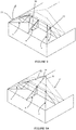
- FIG 1 shows by way of example a main truss 2 and a set of three supplementary trusses 4 prior to assembly together by hinges as discussed above.
- the supplementary trusses are intended to form a hip end of the roof.
- Figure 2 shows the supplementary trusses 4 attached to the main truss 2 by the hinges and folded to lie with their faces against the adjacent face of the main truss for transportation to site and for lifting into position.
- each supplementary truss 4 is hinged to the top chord and bottom chord of the main truss 2 at hinge points 6, the hinge axis of each supplementary truss 4 being vertical considered in relation to the main truss when lying in a vertical plane in its installed condition.
- supplementary trusses are hinged to the top and bottom chords of the main truss by respective upper and lower hinges
- other placements of the hinges would be possible with different designs of main and supplementary trusses.
- the hinges are fixed to the trusses by any suitable means such as screwing, nailing, or gluing, or by nail-plates.
- the primary function of the hinged connection between the supplementary truss and main truss is to enable the supplementary truss to be swung out from its folded condition assumed during transportation and lifting and, as such, the hinges only need to have capacities to withstand the handling and installation loads.
- supplementary fixings would be subsequently installed to withstand the in-service loading, these supplementary fixings being fitted later in the installation process when the majority of the roof structure is in place and braced to provide a stable and safe working environment.
- each of the supplementary trusses is of a length which enables the set of supplementary trusses to be folded flat against the face of the main truss and which is desirable as it enables a series of such truss assemblies to be stacked flat for transportation. Nevertheless the overall concept would still be applicable for use with somewhat longer supplementary trusses in which, in their folded condition for transportation, an outer end of one supplementary truss might overlap the inner end of the adjacent supplementary truss whereby in its folded state it is inclined to the adjacent face of the main truss rather than lying flat against it.
- the supplementary trusses will be accurately positioned relative to the main truss. All that is required is for the supplementary truss to be swung about the vertical hinge axis into its required orientation transverse to the main truss and fastened at its outer end to underlying wall structure, usually the top plate of the underlying wall frame.
- the example which has been given is of a hip formed with three supplementary trusses hinged to the main truss.
- FIG. 3 shows schematically a hip structure formed by a main truss 2 and four supplementary trusses 4.
- hinged assembly of the supplementary trusses to the main truss is undertaken as part of the pre-fabrication in a factory situation, nevertheless many of the advantages provided by the invention can be achieved with hinges pre-installed to the main truss during fabrication with the connection to the supplementary trusses being completed on-site prior to lifting into position with the supplementary trusses being folded against the face of the main truss during lifting.
- This enables the main truss and supplementary trusses to be transported to sites separately and may be necessary in circumstances where the length of the supplementary trusses causes difficulties in transportation when in their folded position against the main truss.
- roof trusses are usually fixed to the underlying top plate or other structure by brackets nailed to the top plate and lower chord of the truss, typically using a nail gun for this purpose.
- a quick-connect two-part fastening may be pre-installed to the truss and top plate during the pre-fabrication of the truss and wall frame, which does not require working with a nail gun at height to make the connection.
- a preferred embodiment of the two-part fastening will now be described in detail.
- the quick-connect fastening comprises male and female parts 10, 12 each of plate-like form, and each preferably being pressed out of metal sheet.
- the female part 12 is shaped to form a series of parallel crests 14 of arcuate form extending across the width of the plate, with valleys 16 in the form of flat lands between adjacent crests. Each crest is apertured along its length with a row of parallel slots 18 which are clearly shown in Figure 5 .
- the male part 10 is profiled in a manner generally corresponding to that of the female part except that each of the crests is defined by a row of generally parallel ribs 20 each of a width and peripheral configuration which enables the rib 20 to fit within one of the slots 18 when the face of one of the two parts is applied against the face of the other part.
- Flat lands 21 are formed between each row of ribs 20.
- the spacing between adjacent ribs 20 in each row of ribs corresponds to that between adjacent slots 18 in each row of slots, and the rows of ribs and slots are at the same spacing.
- a locking lug or tang 22 projects outwardly from the opposite edges of each rib 20, with the two tangs of each rib being in a divergent configuration.
- the configuration is such that when a rib 20 is pressed into a corresponding slot 18 in the female part, its two tangs 22 will deflect resiliently inwardly to enable the rib to enter the slot and when the two tangs have passed through the slot the two tangs will move outwardly under their inherent resilience to their original divergent configuration to engage behind the outer surface of the female plate in the zone of the slots in order to provide a positive locking engagement (see Figure 6 ).
- a locking tang extends from each of two opposite sides of each rib and which is the preferred arrangement, in principle locking could be achieved by just a single tang on each rib.
- resiliently deflectable locking tangs could be formed on one or both sides of each slot with the tangs then being deflected by passage of the ribs through the slots on engagement of the two parts and then returning to their original configuration to positively lock the ribs within the slots against withdrawal.
- one of the two parts is fixed to the top plate with its slotted crests facing upwardly and the other part, in this case therefore the male part, is fixed to the underside of the bottom chord of the truss with its locking ribs facing downwardly.
- Fixing can occur by any suitable means such as screwing, nailing or gluing, or by nail-plates. Nailing or other fixing can occur through holes (the holes are not shown) formed in the flat lands 16, 21 of both plates and which will be in direct contact with the top plate and bottom chord.
- the sizing of the two parts in conjunction with the number of fixing points formed within the matrix can be determined so that even with a maximum expected degree of longitudinal and/or lateral misalignment between the two fastening parts likely to arise when the truss is lowered onto the top plate, a sufficient number of locking ribs will engage within the slots to provide the required secure connection between the truss and top plate.
- the misalignment is likely to be no more than 20mm whereby the two plates of the fastening can be designed to account for the eventuality.
- rafter extensions are hinged to the top chords of the supplementary trusses, preferably at the inner ends thereof.
- the extensions lie along the top chords of the supplementary trusses.
- the rafter extensions are hinged out to extend beyond the main truss into the zone occupied (or to be occupied) by an adjacent main truss of the structure whereby the rafter extensions when fitted to the top chord of the adjacent truss will serve to stabilise that truss during its installation.
- FIG. 8 which shows the truss assembly in exploded form, the rafter extensions are shown in the dashed lines 30, with the hinge connection to the top chord of the associated supplementary trusses being shown at 32.
- Figure 9A shows the extensions 30 having been folded out to their extended configuration after erection of the truss assembly, and being connected to the top chord of the next adjacent main truss 34;
- Figure 9 shows the extensions 30 at the commencement of folding them out.
- Figures 10 to 12 show schematically components for forming a braced structure of part of a roof hip end and to which further trusses or other structure can be subsequently attached without the need for any additional temporary bracing.
- the structure comprises two truncated trusses 50, 52 hinged together at their top chord preferably by two or more hinges 54 spaced along the top chord whereby the two trusses are pivotal about a horizontal axis adjacent the top chords between a folded configuration in which the trusses are in side-by-side relation (see Figures 11 and 11A ) for transportation to site and craning into position on site and an erected configuration in which the two trusses are spread apart at their bottom chords and are thereby mutually inclined (see Figures 10 and 12 ).
- the bottom chords of the two trusses are interconnected by two or more pre-installed links 56 spaced along the bottom chords of the two trusses and which, in the erected configuration form rigid struts to provide rigid bracing between the bottom chords of the two trusses whereby in the erected or deployed configuration the assembly of the two trusses is inherently stable and can be placed in that condition on the top plate of the underlying structure.
- the structure as shown has three such links 56 but it will be understood that the number of required links will be dependent on the overall length of the two trusses.
- links 56 have only been illustrated schematically in the drawings, their structure is such that they must permit the trusses to lie in their folded configuration for transportation and craning and then permit the trusses to be swung into their erected configuration in which they then form rigid struts between the two bottom chords.
- a form of link which can achieve that consists of two arms hinged together at one end and each hinged at an outer end to respective one of the two bottom chords whereby in a folded configuration the two arms are lying in approximately parallel relation or are inclined by a small angle whereas in the erected configuration the two arms are substantially longitudinally aligned to constitute a bracing strut. Rigidity of the strut thus formed can be achieved in a number of different ways.
- One way of achieving this is to configure the hinged connection between the two arms in such a manner that as the trusses reach their fully erected configuration, the arms move slightly beyond a position in which they are longitudinally aligned into a locked over-centre position in which the arms provide a rigid lock against movement of the two bottom chords one towards the other.
- An alternative way of achieving the required rigidity is to provide a screw-operated lock or clamp between the inner ends of the two arms when the erected configuration is reached.
- Figures 13 to 15 relate to a similar concept to that of Figures 10 to 12 but applied to structure for forming a gable end consisting of a central gable truss 60 and two truncated trusses 62, 64 on opposite sides of the central truss 60 and each connected by hinges 54 to an intermediate chord of the central truss for movement about a horizontal axis adjacent the intermediate chord between a folded configuration for transportation and craning into position in which the three trusses lay side-by-side (see Figures 14 and 14A ) to an erected configuration in which the truncated trusses are pivoted outwardly into a stable condition inclined to the central truss (see Figures 13 and 15 ) and rigidly braced in that condition by struts extending between the bottom chord of each of the truncated trusses and the bottom chord of the central truss.
- the struts are formed by links 56 of the form described with reference to Figures 10
Landscapes
- Engineering & Computer Science (AREA)
- Architecture (AREA)
- Civil Engineering (AREA)
- Structural Engineering (AREA)
- Physics & Mathematics (AREA)
- Electromagnetism (AREA)
- General Engineering & Computer Science (AREA)
- Mechanical Engineering (AREA)
- Conveying And Assembling Of Building Elements In Situ (AREA)
- Roof Covering Using Slabs Or Stiff Sheets (AREA)
- Rod-Shaped Construction Members (AREA)
Claims (7)
- Trägeranordnung zur Verwendung im Gebäudebau, die einen Hauptträger (2), der in seiner Einbaulage in einer senkrechten Ebene liegt, und einen oder mehrere zusätzliche Träger (4) umfasst, die so am Hauptträger angebracht sind, dass sie nach dem Aufsetzen der Trägeranordnung quer zu einer Fläche des Hauptträgers verlaufen, wobei der oder jeder zusätzliche Träger angelenkt mit dem Hauptträger verbunden ist, zwecks einer Schwenkbewegung um eine im Wesentlichen senkrechte Achse zwischen einer umgeklappten Gestaltung, in der der zusätzliche Träger angrenzend an die Fläche des Hauptträgers liegt, und einer Aufsetzgestaltung, in der der zusätzliche Träger quer zu der Fläche verläuft, dadurch gekennzeichnet, dass ein oder mehrere der zusätzlichen Träger eine Sparrenverlängerung (30) aufweist, die an einem Obergurt des zusätzlichen Trägers angelenkt ist und während der Anbringung der Trägeranordnung an dem Obergurt entlang liegt, wobei die Gelenkverbindung an dem Obergurt derart ist, dass die Sparrenverlängerung nach der Anbringung nach außen geschwenkt werden kann und sich so über den Hauptträger hinaus erstreckt und eine Aussteifung für einen benachbarten Hauptträger während seiner anschließenden Anbringung bildet.
- Trägeranordnung nach Anspruch 1, wobei die Anordnung zwei oder mehr zusätzliche Träger (4) umfasst, die der Länge nach den Hauptträger (2) entlang beabstandet sind.
- Trägeranordnung nach Anspruch 1 oder 2, wobei der Hauptträger (2) eine Komponente bildet und der oder jeder zusätzliche Träger (4) eine zweite Komponente der Trägeranordnung bildet, wobei die Komponenten aneinander und an einer darunterliegenden oberen Platte über mehrere Sicherungsvorrichtungen befestigt sind, wobei jede Sicherungsvorrichtung einen ersten Teil zur Befestigung an einer der Komponenten und einen zweiten Teil zur Befestigung an der anderen Komponente umfasst, wobei der erste und zweite Teil jeweils plattenartig geformt sind, wobei der erste Teil eine Vielzahl von Arretieransätzen vorsieht und der zweite Teil eine Vielzahl von Öffnungen vorsieht, die in einer Gestaltung angeordnet sind, die der der Arretieransätze des ersten Teils entspricht, sodass die Arretieransätze des ersten Teils, wenn die beiden Teile gemeinsam einander gegenüber verwendet werden, durch die Öffnungen des zweiten Teils verlaufen können und an dem zweiten Teil arretiert werden können, um dadurch die beiden Teile gegen eine Trennung der beiden Teile aneinander zu arretieren, und wobei in jeder der Positionen, in denen ein Untergurt des Hauptträgers und des oder jedes zusätzlichen Trägers an die obere Platte angrenzt, ein Teil der Sicherungsvorrichtung an dem Untergurt fixiert ist, wobei der andere Teil der Sicherungsvorrichtung an dieser Position an der oberen Platte befestigt ist, wobei die jeweiligen Teile der Sicherungsvorrichtungen vor der Anbringung der Trägeranordnung angesetzt werden.
- Trägeranordnung nach Anspruch 3, wobei jeder Arretieransatz des ersten Teils einen Arretierzapfen (22) aufweist, der elastisch einwärts biegbar ist, damit sich der Ansatz mit Zapfen beim Ineinandergreifen der beiden Teile durch die Öffnung bewegt, wobei sich der Zapfen dann nach außen biegt, wenn er sich durch die Öffnung bewegt hat und an der gegenüberliegenden Fläche des zweiten Teils angrenzend an die Öffnung anliegt.
- Trägeranordnung nach Anspruch 3, wobei mindestens ein Rand jeder Öffnung des zweiten Teils einen Arretierzapfen (22) aufweist, der elastisch auswärts biegbar ist, damit sich der Arretieransatz beim Ineinandergreifen der beiden Teile durch die Öffnung bewegen lässt, wobei sich der Zapfen dann nach innen biegt und so den Ansatz arretiert, damit er nicht aus der Öffnung gezogen wird.
- Trägeranordnung nach einem der Ansprüche 3 bis 5, wobei der zweite Teil so geformt ist, dass er eine Reihe paralleler bogenförmiger Erhebungen bildet, wobei jede Erhebung mit einer Reihe paralleler Schlitze (18) versehen ist, die ihre Länge entlang beabstandet sind, wobei die Schlitze die Öffnungen darstellen und der erste Teil so geformt ist, dass er eine Reihe paralleler Erhebungen bildet, wobei jede Erhebung durch eine Reihe von beabstandeten parallelen Rippen (20) definiert ist, wobei jede der Rippen eine derartige Größe aufweist, dass sie in einen der Schlitze des zweiten Teils passt, wodurch jede Rippe einen derartigen Arretieransatz darstellt.
- Trägeranordnung nach einem der Ansprüche 3 bis 6, wobei ein Teil der Sicherungsvorrichtung an einer Fläche des Hauptträgers angebracht ist und der andere Teil der Sicherungsvorrichtung an einem Gurt eines weiteren Trägers befestigt ist, der nach der Anbringung der Trägeranordnung mit dem Hauptträger verbunden werden soll.
Priority Applications (2)
| Application Number | Priority Date | Filing Date | Title |
|---|---|---|---|
| EP18181166.2A EP3404159B1 (de) | 2015-06-02 | 2016-05-24 | Träger zur verwendung im gebäudebau |
| DK18181166.2T DK3404159T3 (da) | 2015-06-02 | 2016-05-24 | Gitre til brug ved bygningskonstruktion |
Applications Claiming Priority (1)
| Application Number | Priority Date | Filing Date | Title |
|---|---|---|---|
| AU2015902094A AU2015902094A0 (en) | 2015-06-02 | Trusses for use in building construction and methods of installing same |
Related Child Applications (2)
| Application Number | Title | Priority Date | Filing Date |
|---|---|---|---|
| EP18181166.2A Division EP3404159B1 (de) | 2015-06-02 | 2016-05-24 | Träger zur verwendung im gebäudebau |
| EP18181166.2A Division-Into EP3404159B1 (de) | 2015-06-02 | 2016-05-24 | Träger zur verwendung im gebäudebau |
Publications (3)
| Publication Number | Publication Date |
|---|---|
| EP3101193A2 EP3101193A2 (de) | 2016-12-07 |
| EP3101193A3 EP3101193A3 (de) | 2017-03-08 |
| EP3101193B1 true EP3101193B1 (de) | 2018-12-26 |
Family
ID=56194228
Family Applications (2)
| Application Number | Title | Priority Date | Filing Date |
|---|---|---|---|
| EP16171136.1A Active EP3101193B1 (de) | 2015-06-02 | 2016-05-24 | Träger zur verwendung im gebäudebau sowie verfahren zur installation davon |
| EP18181166.2A Active EP3404159B1 (de) | 2015-06-02 | 2016-05-24 | Träger zur verwendung im gebäudebau |
Family Applications After (1)
| Application Number | Title | Priority Date | Filing Date |
|---|---|---|---|
| EP18181166.2A Active EP3404159B1 (de) | 2015-06-02 | 2016-05-24 | Träger zur verwendung im gebäudebau |
Country Status (2)
| Country | Link |
|---|---|
| EP (2) | EP3101193B1 (de) |
| DK (1) | DK3404159T3 (de) |
Cited By (1)
| Publication number | Priority date | Publication date | Assignee | Title |
|---|---|---|---|---|
| US11005415B2 (en) * | 2018-08-23 | 2021-05-11 | Jesse Wolf Corsi Henson | Solar shade structure |
Families Citing this family (2)
| Publication number | Priority date | Publication date | Assignee | Title |
|---|---|---|---|---|
| WO2018191116A1 (en) * | 2017-04-13 | 2018-10-18 | Illinois Tool Works Inc. | Method of constructing a truss assembly and supplementary truss for use in a truss assembly for building construction |
| CN113982280A (zh) * | 2021-09-22 | 2022-01-28 | 中国建筑第二工程局有限公司 | 一种复杂式空间桁架整体吊装系统的施工方法 |
Family Cites Families (13)
| Publication number | Priority date | Publication date | Assignee | Title |
|---|---|---|---|---|
| DE696108C (de) * | 1937-08-18 | 1940-09-11 | Paul Kanschat | Loesbare Verbindung zweier Bauteile |
| FR1233563A (fr) * | 1958-03-29 | 1960-10-12 | Metallwerk Friedrichshafen G M | Assemblage par pincement, sans vis, de tôles et bandes profilées |
| US3175650A (en) * | 1962-08-02 | 1965-03-30 | Avco Corp | Trussed structure |
| DE2634179A1 (de) * | 1976-07-29 | 1978-02-02 | Thomas Philip Murphy | Vorrichtung zur verbindung von zwei konstruktionselementen |
| JPH0784776B2 (ja) * | 1987-03-17 | 1995-09-13 | 積水ハウス株式会社 | 屋根パネルの施工方法 |
| JP2847382B2 (ja) * | 1989-04-12 | 1999-01-20 | 積水ハウス株式会社 | 小屋裏の界壁の施工方法 |
| JP2552764B2 (ja) * | 1991-02-04 | 1996-11-13 | ミサワホーム株式会社 | 屋根ユニット |
| CN1046467C (zh) * | 1994-03-03 | 1999-11-17 | 沃尔夫冈·弗勒里希 | 连接板状构件和两个连接板状构件之间的连接装置 |
| ATE239148T1 (de) * | 1997-03-21 | 2003-05-15 | Bruno Alfons Furrer | Verbindungsvorrichtung und verwendung der verbindungsvorrichtung |
| BE1014438A3 (nl) * | 2001-10-24 | 2003-10-07 | Novalati Nv | Inrichting voor het aan elkaar bevestigen van twee elementen. |
| US20100024318A1 (en) * | 2007-02-15 | 2010-02-04 | Shanghai Precision Houses Manufacturing Co., Ltd. | Prefab system, structure and assembling method for all-functional framed buildings |
| CA2913090C (en) * | 2013-05-23 | 2021-08-03 | Les Enceintes Acoustiques Unisson Inc. | Foldable structural truss |
| US9611597B2 (en) * | 2013-08-08 | 2017-04-04 | Safway Services, Llc | Access structure integration assembly and integrated access systems and methods of using the same |
-
2016
- 2016-05-24 EP EP16171136.1A patent/EP3101193B1/de active Active
- 2016-05-24 DK DK18181166.2T patent/DK3404159T3/da active
- 2016-05-24 EP EP18181166.2A patent/EP3404159B1/de active Active
Non-Patent Citations (1)
| Title |
|---|
| None * |
Cited By (1)
| Publication number | Priority date | Publication date | Assignee | Title |
|---|---|---|---|---|
| US11005415B2 (en) * | 2018-08-23 | 2021-05-11 | Jesse Wolf Corsi Henson | Solar shade structure |
Also Published As
| Publication number | Publication date |
|---|---|
| EP3404159A1 (de) | 2018-11-21 |
| EP3101193A2 (de) | 2016-12-07 |
| EP3404159B1 (de) | 2020-05-13 |
| DK3404159T3 (da) | 2020-08-03 |
| EP3101193A3 (de) | 2017-03-08 |
Similar Documents
| Publication | Publication Date | Title |
|---|---|---|
| AU2023229610B2 (en) | Trusses for use in building construction and methods of installing same | |
| US5857292A (en) | Roof support apparatus | |
| US5704170A (en) | Apparatus for roof support | |
| US20080282635A1 (en) | Purlin Bracing System for Metal Building Roof | |
| EP3101193B1 (de) | Träger zur verwendung im gebäudebau sowie verfahren zur installation davon | |
| US12116769B2 (en) | Connector device, system and method for constructing a roof for a building | |
| US7325362B1 (en) | Steel roof truss system | |
| EP3350382B1 (de) | Scherübertragungssystem | |
| AU2018202473B2 (en) | Method of constructing a truss assembly and supplementary truss for use in a truss assembly for building construction | |
| GB2480994A (en) | Timber I-beams and panels in attic roof structures | |
| NZ714131B2 (en) | Trusses for use in building construction and methods of installing same | |
| EP3580408B1 (de) | Wiederverwendbares modulares gebäude und verfahren zu dessen errichtung | |
| AU2015249147B2 (en) | Quick-connect fastening for use in building construction | |
| US9725869B2 (en) | Building assembly for greenhouses and other buildings | |
| JP7218665B2 (ja) | 屋根構造、及び屋根構造施工方法 | |
| NZ713944B2 (en) | Quick-connect fastening for use in building construction | |
| US12435533B2 (en) | Construction system | |
| IE20180036A1 (en) | A roofing component | |
| US12180708B2 (en) | Loft conversion | |
| WO2018162796A1 (en) | Method for building a roof | |
| JPH10102664A (ja) | 独立小屋束 | |
| AU2753702A (en) | A modular roofing system | |
| AU2021221766A1 (en) | Cold-formed portal framed structures and components for such structures | |
| WO1998021426A1 (en) | A roof for a house | |
| AU2019204861A1 (en) | Hinged Roof Module |
Legal Events
| Date | Code | Title | Description |
|---|---|---|---|
| PUAI | Public reference made under article 153(3) epc to a published international application that has entered the european phase |
Free format text: ORIGINAL CODE: 0009012 |
|
| STAA | Information on the status of an ep patent application or granted ep patent |
Free format text: STATUS: THE APPLICATION HAS BEEN PUBLISHED |
|
| AK | Designated contracting states |
Kind code of ref document: A2 Designated state(s): AL AT BE BG CH CY CZ DE DK EE ES FI FR GB GR HR HU IE IS IT LI LT LU LV MC MK MT NL NO PL PT RO RS SE SI SK SM TR |
|
| AX | Request for extension of the european patent |
Extension state: BA ME |
|
| PUAL | Search report despatched |
Free format text: ORIGINAL CODE: 0009013 |
|
| AK | Designated contracting states |
Kind code of ref document: A3 Designated state(s): AL AT BE BG CH CY CZ DE DK EE ES FI FR GB GR HR HU IE IS IT LI LT LU LV MC MK MT NL NO PL PT RO RS SE SI SK SM TR |
|
| AX | Request for extension of the european patent |
Extension state: BA ME |
|
| RIC1 | Information provided on ipc code assigned before grant |
Ipc: E04B 1/26 20060101ALI20170202BHEP Ipc: E04C 3/11 20060101ALI20170202BHEP Ipc: E04C 3/00 20060101ALI20170202BHEP Ipc: E04B 7/06 20060101ALI20170202BHEP Ipc: E04B 7/02 20060101AFI20170202BHEP Ipc: E04B 1/24 20060101ALI20170202BHEP Ipc: F16B 5/07 20060101ALI20170202BHEP Ipc: E04B 7/24 20060101ALI20170202BHEP Ipc: E04C 3/17 20060101ALI20170202BHEP |
|
| STAA | Information on the status of an ep patent application or granted ep patent |
Free format text: STATUS: REQUEST FOR EXAMINATION WAS MADE |
|
| 17P | Request for examination filed |
Effective date: 20170906 |
|
| RBV | Designated contracting states (corrected) |
Designated state(s): AL AT BE BG CH CY CZ DE DK EE ES FI FR GB GR HR HU IE IS IT LI LT LU LV MC MK MT NL NO PL PT RO RS SE SI SK SM TR |
|
| STAA | Information on the status of an ep patent application or granted ep patent |
Free format text: STATUS: EXAMINATION IS IN PROGRESS |
|
| 17Q | First examination report despatched |
Effective date: 20180119 |
|
| GRAP | Despatch of communication of intention to grant a patent |
Free format text: ORIGINAL CODE: EPIDOSNIGR1 |
|
| STAA | Information on the status of an ep patent application or granted ep patent |
Free format text: STATUS: GRANT OF PATENT IS INTENDED |
|
| INTG | Intention to grant announced |
Effective date: 20180531 |
|
| GRAS | Grant fee paid |
Free format text: ORIGINAL CODE: EPIDOSNIGR3 |
|
| GRAA | (expected) grant |
Free format text: ORIGINAL CODE: 0009210 |
|
| STAA | Information on the status of an ep patent application or granted ep patent |
Free format text: STATUS: THE PATENT HAS BEEN GRANTED |
|
| AK | Designated contracting states |
Kind code of ref document: B1 Designated state(s): AL AT BE BG CH CY CZ DE DK EE ES FI FR GB GR HR HU IE IS IT LI LT LU LV MC MK MT NL NO PL PT RO RS SE SI SK SM TR |
|
| REG | Reference to a national code |
Ref country code: GB Ref legal event code: FG4D |
|
| REG | Reference to a national code |
Ref country code: CH Ref legal event code: EP |
|
| REG | Reference to a national code |
Ref country code: AT Ref legal event code: REF Ref document number: 1081605 Country of ref document: AT Kind code of ref document: T Effective date: 20190115 |
|
| REG | Reference to a national code |
Ref country code: DE Ref legal event code: R096 Ref document number: 602016008588 Country of ref document: DE |
|
| REG | Reference to a national code |
Ref country code: IE Ref legal event code: FG4D |
|
| PG25 | Lapsed in a contracting state [announced via postgrant information from national office to epo] |
Ref country code: FI Free format text: LAPSE BECAUSE OF FAILURE TO SUBMIT A TRANSLATION OF THE DESCRIPTION OR TO PAY THE FEE WITHIN THE PRESCRIBED TIME-LIMIT Effective date: 20181226 Ref country code: LV Free format text: LAPSE BECAUSE OF FAILURE TO SUBMIT A TRANSLATION OF THE DESCRIPTION OR TO PAY THE FEE WITHIN THE PRESCRIBED TIME-LIMIT Effective date: 20181226 Ref country code: HR Free format text: LAPSE BECAUSE OF FAILURE TO SUBMIT A TRANSLATION OF THE DESCRIPTION OR TO PAY THE FEE WITHIN THE PRESCRIBED TIME-LIMIT Effective date: 20181226 Ref country code: BG Free format text: LAPSE BECAUSE OF FAILURE TO SUBMIT A TRANSLATION OF THE DESCRIPTION OR TO PAY THE FEE WITHIN THE PRESCRIBED TIME-LIMIT Effective date: 20190326 Ref country code: NO Free format text: LAPSE BECAUSE OF FAILURE TO SUBMIT A TRANSLATION OF THE DESCRIPTION OR TO PAY THE FEE WITHIN THE PRESCRIBED TIME-LIMIT Effective date: 20190326 Ref country code: LT Free format text: LAPSE BECAUSE OF FAILURE TO SUBMIT A TRANSLATION OF THE DESCRIPTION OR TO PAY THE FEE WITHIN THE PRESCRIBED TIME-LIMIT Effective date: 20181226 |
|
| REG | Reference to a national code |
Ref country code: NL Ref legal event code: MP Effective date: 20181226 |
|
| REG | Reference to a national code |
Ref country code: LT Ref legal event code: MG4D |
|
| PG25 | Lapsed in a contracting state [announced via postgrant information from national office to epo] |
Ref country code: AL Free format text: LAPSE BECAUSE OF FAILURE TO SUBMIT A TRANSLATION OF THE DESCRIPTION OR TO PAY THE FEE WITHIN THE PRESCRIBED TIME-LIMIT Effective date: 20181226 Ref country code: GR Free format text: LAPSE BECAUSE OF FAILURE TO SUBMIT A TRANSLATION OF THE DESCRIPTION OR TO PAY THE FEE WITHIN THE PRESCRIBED TIME-LIMIT Effective date: 20190327 Ref country code: SE Free format text: LAPSE BECAUSE OF FAILURE TO SUBMIT A TRANSLATION OF THE DESCRIPTION OR TO PAY THE FEE WITHIN THE PRESCRIBED TIME-LIMIT Effective date: 20181226 Ref country code: RS Free format text: LAPSE BECAUSE OF FAILURE TO SUBMIT A TRANSLATION OF THE DESCRIPTION OR TO PAY THE FEE WITHIN THE PRESCRIBED TIME-LIMIT Effective date: 20181226 |
|
| REG | Reference to a national code |
Ref country code: AT Ref legal event code: MK05 Ref document number: 1081605 Country of ref document: AT Kind code of ref document: T Effective date: 20181226 |
|
| PG25 | Lapsed in a contracting state [announced via postgrant information from national office to epo] |
Ref country code: NL Free format text: LAPSE BECAUSE OF FAILURE TO SUBMIT A TRANSLATION OF THE DESCRIPTION OR TO PAY THE FEE WITHIN THE PRESCRIBED TIME-LIMIT Effective date: 20181226 |
|
| PG25 | Lapsed in a contracting state [announced via postgrant information from national office to epo] |
Ref country code: CZ Free format text: LAPSE BECAUSE OF FAILURE TO SUBMIT A TRANSLATION OF THE DESCRIPTION OR TO PAY THE FEE WITHIN THE PRESCRIBED TIME-LIMIT Effective date: 20181226 Ref country code: IT Free format text: LAPSE BECAUSE OF FAILURE TO SUBMIT A TRANSLATION OF THE DESCRIPTION OR TO PAY THE FEE WITHIN THE PRESCRIBED TIME-LIMIT Effective date: 20181226 Ref country code: PT Free format text: LAPSE BECAUSE OF FAILURE TO SUBMIT A TRANSLATION OF THE DESCRIPTION OR TO PAY THE FEE WITHIN THE PRESCRIBED TIME-LIMIT Effective date: 20190426 Ref country code: ES Free format text: LAPSE BECAUSE OF FAILURE TO SUBMIT A TRANSLATION OF THE DESCRIPTION OR TO PAY THE FEE WITHIN THE PRESCRIBED TIME-LIMIT Effective date: 20181226 Ref country code: PL Free format text: LAPSE BECAUSE OF FAILURE TO SUBMIT A TRANSLATION OF THE DESCRIPTION OR TO PAY THE FEE WITHIN THE PRESCRIBED TIME-LIMIT Effective date: 20181226 |
|
| PG25 | Lapsed in a contracting state [announced via postgrant information from national office to epo] |
Ref country code: EE Free format text: LAPSE BECAUSE OF FAILURE TO SUBMIT A TRANSLATION OF THE DESCRIPTION OR TO PAY THE FEE WITHIN THE PRESCRIBED TIME-LIMIT Effective date: 20181226 Ref country code: SM Free format text: LAPSE BECAUSE OF FAILURE TO SUBMIT A TRANSLATION OF THE DESCRIPTION OR TO PAY THE FEE WITHIN THE PRESCRIBED TIME-LIMIT Effective date: 20181226 Ref country code: SK Free format text: LAPSE BECAUSE OF FAILURE TO SUBMIT A TRANSLATION OF THE DESCRIPTION OR TO PAY THE FEE WITHIN THE PRESCRIBED TIME-LIMIT Effective date: 20181226 Ref country code: IS Free format text: LAPSE BECAUSE OF FAILURE TO SUBMIT A TRANSLATION OF THE DESCRIPTION OR TO PAY THE FEE WITHIN THE PRESCRIBED TIME-LIMIT Effective date: 20190426 Ref country code: RO Free format text: LAPSE BECAUSE OF FAILURE TO SUBMIT A TRANSLATION OF THE DESCRIPTION OR TO PAY THE FEE WITHIN THE PRESCRIBED TIME-LIMIT Effective date: 20181226 |
|
| REG | Reference to a national code |
Ref country code: DE Ref legal event code: R097 Ref document number: 602016008588 Country of ref document: DE |
|
| PG25 | Lapsed in a contracting state [announced via postgrant information from national office to epo] |
Ref country code: DK Free format text: LAPSE BECAUSE OF FAILURE TO SUBMIT A TRANSLATION OF THE DESCRIPTION OR TO PAY THE FEE WITHIN THE PRESCRIBED TIME-LIMIT Effective date: 20181226 Ref country code: AT Free format text: LAPSE BECAUSE OF FAILURE TO SUBMIT A TRANSLATION OF THE DESCRIPTION OR TO PAY THE FEE WITHIN THE PRESCRIBED TIME-LIMIT Effective date: 20181226 |
|
| PLBE | No opposition filed within time limit |
Free format text: ORIGINAL CODE: 0009261 |
|
| STAA | Information on the status of an ep patent application or granted ep patent |
Free format text: STATUS: NO OPPOSITION FILED WITHIN TIME LIMIT |
|
| 26N | No opposition filed |
Effective date: 20190927 |
|
| REG | Reference to a national code |
Ref country code: CH Ref legal event code: PL |
|
| PG25 | Lapsed in a contracting state [announced via postgrant information from national office to epo] |
Ref country code: CH Free format text: LAPSE BECAUSE OF NON-PAYMENT OF DUE FEES Effective date: 20190531 Ref country code: LI Free format text: LAPSE BECAUSE OF NON-PAYMENT OF DUE FEES Effective date: 20190531 Ref country code: MC Free format text: LAPSE BECAUSE OF FAILURE TO SUBMIT A TRANSLATION OF THE DESCRIPTION OR TO PAY THE FEE WITHIN THE PRESCRIBED TIME-LIMIT Effective date: 20181226 |
|
| REG | Reference to a national code |
Ref country code: BE Ref legal event code: MM Effective date: 20190531 |
|
| PG25 | Lapsed in a contracting state [announced via postgrant information from national office to epo] |
Ref country code: LU Free format text: LAPSE BECAUSE OF NON-PAYMENT OF DUE FEES Effective date: 20190524 Ref country code: SI Free format text: LAPSE BECAUSE OF FAILURE TO SUBMIT A TRANSLATION OF THE DESCRIPTION OR TO PAY THE FEE WITHIN THE PRESCRIBED TIME-LIMIT Effective date: 20181226 |
|
| PG25 | Lapsed in a contracting state [announced via postgrant information from national office to epo] |
Ref country code: TR Free format text: LAPSE BECAUSE OF FAILURE TO SUBMIT A TRANSLATION OF THE DESCRIPTION OR TO PAY THE FEE WITHIN THE PRESCRIBED TIME-LIMIT Effective date: 20181226 |
|
| PG25 | Lapsed in a contracting state [announced via postgrant information from national office to epo] |
Ref country code: IE Free format text: LAPSE BECAUSE OF NON-PAYMENT OF DUE FEES Effective date: 20190524 |
|
| PG25 | Lapsed in a contracting state [announced via postgrant information from national office to epo] |
Ref country code: BE Free format text: LAPSE BECAUSE OF NON-PAYMENT OF DUE FEES Effective date: 20190531 |
|
| PG25 | Lapsed in a contracting state [announced via postgrant information from national office to epo] |
Ref country code: CY Free format text: LAPSE BECAUSE OF FAILURE TO SUBMIT A TRANSLATION OF THE DESCRIPTION OR TO PAY THE FEE WITHIN THE PRESCRIBED TIME-LIMIT Effective date: 20181226 |
|
| PG25 | Lapsed in a contracting state [announced via postgrant information from national office to epo] |
Ref country code: HU Free format text: LAPSE BECAUSE OF FAILURE TO SUBMIT A TRANSLATION OF THE DESCRIPTION OR TO PAY THE FEE WITHIN THE PRESCRIBED TIME-LIMIT; INVALID AB INITIO Effective date: 20160524 Ref country code: MT Free format text: LAPSE BECAUSE OF FAILURE TO SUBMIT A TRANSLATION OF THE DESCRIPTION OR TO PAY THE FEE WITHIN THE PRESCRIBED TIME-LIMIT Effective date: 20181226 |
|
| PG25 | Lapsed in a contracting state [announced via postgrant information from national office to epo] |
Ref country code: MK Free format text: LAPSE BECAUSE OF FAILURE TO SUBMIT A TRANSLATION OF THE DESCRIPTION OR TO PAY THE FEE WITHIN THE PRESCRIBED TIME-LIMIT Effective date: 20181226 |
|
| P01 | Opt-out of the competence of the unified patent court (upc) registered |
Effective date: 20230606 |
|
| PGFP | Annual fee paid to national office [announced via postgrant information from national office to epo] |
Ref country code: DE Payment date: 20250529 Year of fee payment: 10 |
|
| PGFP | Annual fee paid to national office [announced via postgrant information from national office to epo] |
Ref country code: GB Payment date: 20250527 Year of fee payment: 10 |
|
| PGFP | Annual fee paid to national office [announced via postgrant information from national office to epo] |
Ref country code: FR Payment date: 20250526 Year of fee payment: 10 |