EP3101280A1 - Zentrifugallüfter und klimaanlage - Google Patents
Zentrifugallüfter und klimaanlage Download PDFInfo
- Publication number
- EP3101280A1 EP3101280A1 EP14880164.0A EP14880164A EP3101280A1 EP 3101280 A1 EP3101280 A1 EP 3101280A1 EP 14880164 A EP14880164 A EP 14880164A EP 3101280 A1 EP3101280 A1 EP 3101280A1
- Authority
- EP
- European Patent Office
- Prior art keywords
- shroud
- centrifugal fan
- air
- extension part
- flow
- Prior art date
- Legal status (The legal status is an assumption and is not a legal conclusion. Google has not performed a legal analysis and makes no representation as to the accuracy of the status listed.)
- Granted
Links
Images


Classifications
-
- F—MECHANICAL ENGINEERING; LIGHTING; HEATING; WEAPONS; BLASTING
- F04—POSITIVE - DISPLACEMENT MACHINES FOR LIQUIDS; PUMPS FOR LIQUIDS OR ELASTIC FLUIDS
- F04D—NON-POSITIVE-DISPLACEMENT PUMPS
- F04D29/00—Details, component parts, or accessories
- F04D29/40—Casings; Connections of working fluid
- F04D29/42—Casings; Connections of working fluid for radial or helico-centrifugal pumps
- F04D29/4206—Casings; Connections of working fluid for radial or helico-centrifugal pumps especially adapted for elastic fluid pumps
- F04D29/4213—Casings; Connections of working fluid for radial or helico-centrifugal pumps especially adapted for elastic fluid pumps suction ports
-
- F—MECHANICAL ENGINEERING; LIGHTING; HEATING; WEAPONS; BLASTING
- F04—POSITIVE - DISPLACEMENT MACHINES FOR LIQUIDS; PUMPS FOR LIQUIDS OR ELASTIC FLUIDS
- F04D—NON-POSITIVE-DISPLACEMENT PUMPS
- F04D25/00—Pumping installations or systems
- F04D25/02—Units comprising pumps and their driving means
- F04D25/08—Units comprising pumps and their driving means the working fluid being air, e.g. for ventilation
- F04D25/12—Units comprising pumps and their driving means the working fluid being air, e.g. for ventilation the unit being adapted for mounting in apertures
-
- F—MECHANICAL ENGINEERING; LIGHTING; HEATING; WEAPONS; BLASTING
- F04—POSITIVE - DISPLACEMENT MACHINES FOR LIQUIDS; PUMPS FOR LIQUIDS OR ELASTIC FLUIDS
- F04D—NON-POSITIVE-DISPLACEMENT PUMPS
- F04D29/00—Details, component parts, or accessories
- F04D29/08—Sealings
- F04D29/16—Sealings between pressure and suction sides
- F04D29/161—Sealings between pressure and suction sides especially adapted for elastic fluid pumps
- F04D29/162—Sealings between pressure and suction sides especially adapted for elastic fluid pumps of a centrifugal flow wheel
-
- F—MECHANICAL ENGINEERING; LIGHTING; HEATING; WEAPONS; BLASTING
- F04—POSITIVE - DISPLACEMENT MACHINES FOR LIQUIDS; PUMPS FOR LIQUIDS OR ELASTIC FLUIDS
- F04D—NON-POSITIVE-DISPLACEMENT PUMPS
- F04D29/00—Details, component parts, or accessories
- F04D29/26—Rotors specially for elastic fluids
- F04D29/28—Rotors specially for elastic fluids for centrifugal or helico-centrifugal pumps for radial-flow or helico-centrifugal pumps
- F04D29/281—Rotors specially for elastic fluids for centrifugal or helico-centrifugal pumps for radial-flow or helico-centrifugal pumps for fans or blowers
-
- F—MECHANICAL ENGINEERING; LIGHTING; HEATING; WEAPONS; BLASTING
- F24—HEATING; RANGES; VENTILATING
- F24F—AIR-CONDITIONING; AIR-HUMIDIFICATION; VENTILATION; USE OF AIR CURRENTS FOR SCREENING
- F24F1/00—Room units for air-conditioning, e.g. separate or self-contained units or units receiving primary air from a central station
- F24F1/0007—Indoor units, e.g. fan coil units
- F24F1/0018—Indoor units, e.g. fan coil units characterised by fans
- F24F1/0022—Centrifugal or radial fans
-
- F—MECHANICAL ENGINEERING; LIGHTING; HEATING; WEAPONS; BLASTING
- F24—HEATING; RANGES; VENTILATING
- F24F—AIR-CONDITIONING; AIR-HUMIDIFICATION; VENTILATION; USE OF AIR CURRENTS FOR SCREENING
- F24F1/00—Room units for air-conditioning, e.g. separate or self-contained units or units receiving primary air from a central station
- F24F1/0007—Indoor units, e.g. fan coil units
- F24F1/0043—Indoor units, e.g. fan coil units characterised by mounting arrangements
- F24F1/0047—Indoor units, e.g. fan coil units characterised by mounting arrangements mounted in the ceiling or at the ceiling
-
- F—MECHANICAL ENGINEERING; LIGHTING; HEATING; WEAPONS; BLASTING
- F05—INDEXING SCHEMES RELATING TO ENGINES OR PUMPS IN VARIOUS SUBCLASSES OF CLASSES F01-F04
- F05D—INDEXING SCHEME FOR ASPECTS RELATING TO NON-POSITIVE-DISPLACEMENT MACHINES OR ENGINES, GAS-TURBINES OR JET-PROPULSION PLANTS
- F05D2250/00—Geometry
- F05D2250/50—Inlet or outlet
- F05D2250/52—Outlet
Definitions
- the present invention relates to a centrifugal fan and an air-conditioning device.
- PTL1 discloses a centrifugal fan which is configured in such a manner that an outer peripheral section of a shroud which is positioned on an outlet side of the centrifugal fan is inclined to an inlet side, and the flow passage area of any cross-section in the circumferential direction is greater than the cross-sectional area of the blade inlet in the circumferential direction at the position where a blade inflow section of a shroud inner peripheral section intersects with the shroud.
- the outlet flow of the centrifugal fan is directed towards the outlet port of the air blower main body, and the velocity of the outlet flow from the centrifugal fan is reduced by the velocity of the flow at the outer peripheral section of the shroud, thereby reducing the impact on the housing side walls of the air blower.
- PTL2 discloses a centrifugal fan which is configured in such a manner that a smallest section where the cross-sectional area is smallest is formed at an intermediate point of an air flow passage surrounded by a main plate, blades and a shroud, and the cross-sectional area of the air flow passage increases gradually from the smallest section to the outer peripheral section of the shroud.
- PTL3 discloses a centrifugal fan in which a guide section extending to an inlet side is formed in an outside portion of a shroud in the radial direction.
- the air flow blown out from the centrifugal fan is a high-velocity flow and therefore an eddy occurs due to velocity differential at the periphery of the outlet port.
- an eddy caused by a velocity differential between the main flow and the slower air flow on the upper surface of the shroud increases the air passage resistance by closing off the outlet flow passage, thus leading to increased power consumption of the fan and increased noise due to increase in the velocity of the air flow passing through the narrow flow passage.
- the present invention was devised in view of the foregoing, an object thereof being to provide a centrifugal fan capable of suppressing increase in air passage resistance.
- the present invention is a centrifugal fan including a main plate, a shroud having a fan inlet port, and a plurality of vanes provided between the main plate and the shroud, wherein the shroud has a shroud main body section and an extension part, the extension part is a portion extending from a shroud outer peripheral end section of the shroud main body section to an upstream side when viewed in a direction parallel to an axis of rotation, a radially outside surface of the shroud main body section, and a radially inside surface of the extension part constitute a concave rounded surface, and a direction of recess of the concave rounded surface is towards the upstream side when viewed in the direction parallel to the axis of rotation.
- a configuration may be disposed in which a plurality of projections extending in the radial direction are formed on the concave rounded surface.
- a configuration may be adopted wherein the plurality of projections are inclined in such a manner that, in plan view, the portion of each projection on the outside in the radial direction is positioned rearwards in a direction of rotation of the centrifugal fan, with respect to the portion of the projection on the inside in the radial direction.
- the present invention provides an air-conditioning device including a centrifugal fan relating to the present invention as described above, and a heat exchanger disposed on the outside of the centrifugal fan.
- a configuration may be adopted, wherein an end section of the heat exchanger on the side of an air-conditioning device outlet port is closer to the air-conditioning device outlet port than an inlet-side end section of the centrifugal fan is, when viewed in a direction parallel to an axis of rotation.
- Fig. 1 is a perspective diagram showing a centrifugal fan relating to a first embodiment of the present invention
- Fig. 2 is a cross-sectional diagram of the centrifugal fan in Fig. 1
- Fig. 3 is a diagram showing an internal structure of an air-conditioning device relating to a first embodiment
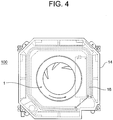
- Fig. 4 is a diagram showing an internal structure of the air-conditioning device in Fig. 3 , viewed in the direction of the arrow IV in Fig. 3 .
- the centrifugal fan 1 is provided with a main plate 2, a shroud 3 and a plurality of vanes 4.
- the main plate 2 and the shroud 3 face each other in the direction of extension of an axis of rotation 5, and are disposed at an interval apart in the direction of extension of the axis of rotation 5.
- a plurality of vanes 4 extend in the direction of extension of the axis of rotation 5, between the main plate 2 and the shroud 3, and couple together the main plate 2 and the shroud 3.
- the vanes may have a hollow internal structure in order to reduce the weight thereof.
- the centrifugal fan 1 is supported rotatably, and the main plate 2, the shroud 3 and the plurality of vanes 4 rotate in a unified fashion.
- a fan inlet port 3a for taking in air is formed in a central portion of the shroud 3.
- the shroud 3 is configured such that an end section of a shroud main body section 11 which constitutes the fan outlet port 22 in conjunction with the main plate 2 (in other words, the shroud outer peripheral end section 8) is positioned towards the outer side in the radial direction and closer to the main plate 2, than an end section of the shroud main body section 11 which constitutes the fan inlet port 3a (in other words, the inlet-side end section 28) is.
- the shroud 3 also has a ring-shaped extension part 10.
- This extension part 10 is a portion which extends from the shroud outer peripheral end section 8, which is the outermost end portion of the shroud main body section 11, to the upstream side (to the side of the fan inlet port 3a), in a direction parallel to the axis of rotation 5.
- the ring-shaped extension part 10 surrounds the shroud main body section 11.
- the radially outside surface of the shroud main body section 11 and the radially inside surface of the extension part 10 constitute a concave rounded surface.
- This concave rounded surface 30 is configured by a single circular arc, or by a combination of a plurality of circular arcs, when viewed in a longitudinal cross-section including the axis of rotation 5 (as seen in Fig. 5 which is one cross-section of a longitudinal cross-section of this kind).
- the direction of the recess in the concave rounded surface 30 is towards the upstream side (the side of the fan inlet port 3a) in a direction parallel to the axis of rotation 5.
- an air-conditioning device 100 provided with the centrifugal fan 1 is also described here.
- the air-conditioning device 100 has the abovementioned centrifugal fan 1, and a motor 15 which causes the centrifugal fan 1 to rotate, in the center of the interior of a unit which is configured by a ceiling plate 13 and side plate 14.
- Fig. 4 is a perspective view which prioritizes a view of the internal configuration of the unit.
- a heat exchanger 16 which carries out heat exchange with the air flowing out from the centrifugal fan 1 is provided on the outside (downstream side) of the centrifugal fan 1.
- the heat exchanger 16 is disposed so as to surround the centrifugal fan 1.
- the heat exchanger 16 is disposed so as to follow the main four surfaces of the side plates 14, and extends so as to form substantially a quadrilateral shape.
- a cosmetic plate 17 facing into the room 102 is provided on the lower side of the unit.
- An air-conditioning device inlet port 18 and a plurality of air-conditioning device outlet ports 19 are provided in the center of the cosmetic plate 17.
- the air-conditioning device inlet port 18 occupies the central region of the axis of rotation 5 and the periphery thereof, and the air-conditioning device outlet port 19 occupies the region peripheral to the air-conditioning device inlet port 18.
- An air flow directing vane 20 is provided on the air-conditioning device outlet port 19 to control the direction of the discharged air flow.
- Fig. 3 illustrates the flow of air 21 as viewed in the whole of the air-conditioning device 100 which is configured in this way.
- the air in the room 102 is sucked inside the unit from the air-conditioning device inlet port 18, by the rotation of the centrifugal fan 1.
- the air flow that flows in from the fan inlet port 3a of the centrifugal fan 1, while flowing between the vanes, receives energy from the vanes 4 and the pressure thereof is thereby raised, while the orientation of the air flow is changed from the fan axis direction towards the outside in the radial direction, and the air is blown out from the fan outlet port 22.
- the air flow blown out in a rotating fashion by the centrifugal fan 1 is regulated in temperature, principally, and is blown out from the air-conditioning device outlet port 19 to the room 102.
- the first embodiment and embodiments indicated below describe an air-conditioning device as one example of an air blower in which a flow of air sucked in from a device inlet port (fan inlet port) is made to perform a U turn in the centrifugal fan and the air flows to the device outlet port (in the present embodiment, the air-conditioning device outlet port) in the same direction as on the upstream side of the device inlet port (fan inlet port).
- Fig. 5 is a diagram showing a view of the flow relating to the centrifugal fan according to the first embodiment.
- Fig. 6 is a diagram showing a view of the flow relating to a centrifugal fan according to a first illustrative example
- Fig. 7 is a diagram showing a view of the flow relating to a centrifugal fan according to a second illustrative example.
- Fig. 5 , Fig. 6 and Fig. 7 all show only the centrifugal fan, the bell mouth 41 and the heat exchanger 16, and omit the interior of the unit, in order to aid understanding.
- a virtual centrifugal fan 61 in a virtual centrifugal fan 61 according to a second illustrative example in which a peripheral wall section 61a that is simply folded back on the fan inlet port 3a side is formed on the outer peripheral end section of the shroud, the flow 7 blown out from the fan outlet port 22 subsequently flows along the peripheral wall section 61a due to the Coanda effect, and furthermore, a flow that has separated from the peripheral wall section 61a generates an eddy 23 due to a velocity differential with respect to the air on the inner side in the radial direction, between the shroud and the bell mouth.
- the eddy 23 Due to the eddy 23 which is generated in this way, it is difficult to obtain a flow that reaches to the surface of the main body section of the shroud and to the vicinity of the corner section 61b of the base portion of the peripheral wall section 61a, as indicated by reference numeral 23a. Therefore, the eddy 23 is not readily contained on the inner side of the peripheral wall section 61a in the radial direction, and expands towards the outer side in the radial direction, beyond the outer diameter of the centrifugal fan 1. Therefore, similarly to the case of the first illustrative example in Fig. 6 , there is a problem in that the flow passage width 24 is narrow, and consequently, the air passage resistance upon passing of the flow 7 is large.
- an extension part 10 which extends to the fan inlet port 3a side when viewed in the direction parallel to the axis of rotation 5, on the outer peripheral end section 8 of the shroud which constitutes the fan outlet port, and the shroud constituting surface 12 from the front end 9 of the extension part 10 to the shroud main body section 11 is formed by a concave rounded surface 30 which is recessed towards the side of the fan inlet port 3a as viewed in the direction parallel to the axis of rotation 5. Consequently, although, initially, the flow 7 which is blown out from the fan outlet port 22 generates an eddy 23, similarly to the case in Fig.
- the eddy 23 thus generated flows along the shroud constituting surface 12 which is the concave rounded surface 30, and is readily contained to the inside of the extension part 10 in the radial direction. Consequently, the flow passage width 24 can be kept large in the region sandwiched between the eddy 23 and the heat exchanger 16, and increase in the air passage resistance of the flow 7 can be suppressed. Furthermore, since the eddy can be contained in the concave region, then it is possible to reduce the size of the eddy and disturbance can be reduced.
- the centrifugal fan and air-conditioning device As described above, according to the centrifugal fan and air-conditioning device according to the first embodiment, it is possible to achieve reduced noise by suppressing disturbance and reducing the outlet air flow velocity, as well as reducing the power consumption of the motor by reducing the air passage resistance.
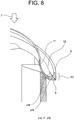
- Fig. 8 and Fig. 9 illustrate a first modification of the first embodiment.
- Fig. 8 is a diagram of a similar mode to Fig. 2 , relating to the portion near the extension part of the first modification.
- Fig. 9 is a diagram of a similar mode to Fig. 5 , relating to the first modification.
- the concave rounded surface has a more gentle curve than the curved surface which is constituted by the shroud outer peripheral end section on the outlet port side, and the extension part (a corner-shaped surface is included as one mode of the curved surface). Therefore, the eddy 23 generated flows smoothly along the constituting surfaces, and the eddy can be stabilized without leaking to the outside of the shroud. More specifically, the air flow which is blown out after passing between the vanes flows in a tight spiral from the shroud main body section to the extension part due to the Coanda effect, does not readily expand to the outside in the radial direction and therefore is not liable to close off the flow passage between the fan and the heat exchanger.
- Fig. 10 is a diagram of a similar mode to Fig. 5 , relating to the second modification.
- This second modification is characterized in that the outer diameter Rsh of the shroud outer peripheral end section 8 is made larger than the outer diameter RO of the main plate 2, in the configuration shown in Fig. 1 to Fig. 7 described above, or the configuration shown in Fig. 8 and Fig. 9 . Therefore, the concave region constituted by the radially outside surface of the shroud main body section 11 and the radially inside surface of the extension part 10 becomes wider, the eddy generated between the fan and the heat exchanger is retained readily within the concave region, and a broad flow passage can easily be guaranteed.
- the first modification and the second modification are both similar to the configuration of the first embodiment illustrated in Fig. 1 to Fig. 7 , apart from the portion described above.
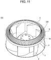
- FIG. 11 is a diagram of a similar mode to Fig. 1 , relating to a second embodiment of the present invention.
- the second embodiment is similar to the first embodiment described above, with the exception of the part described below.
- a plurality of projections 125 are formed in the shroud 3 on the concave rounded surface 30 which is constituted by the radially outside surface of the shroud main body section 11 and the radially inside surface of the extension part 10. These projections 125 extend from the front end 9 of the extension part 10 to the vicinity of the fan inlet port 3a of the shroud main body section 11. Furthermore, the plurality of projections 125 extend from the inside to the outside in the radial direction, and in particular, in the specific example shown in Fig. 11 , the projections 125 extend in a radiating fashion following the radial direction, when viewed in plan view from the direction of the axis of rotation 5.
- the second embodiment similarly to the first embodiment, it is possible to reduce the blowing air flow velocity, and it is possible to achieve a centrifugal fan which reduces the power consumption by reduction of the air passage resistance, and which reduces noise through reduction of the disturbance and the flow velocity.
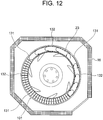
- the air blower and air-conditioning device are surrounded by a square-shaped heat exchanger, and since the mode of the air passage is not axially symmetrical, then the air passage resistance varies depending on the location, the flow volume and velocity of the air flowing between the vanes varies, and therefore variations occur in the outlet flow.
- Fig. 12 firstly, in the area 131 where the centrifugal fan 101 and the heat exchanger 16 are separated, the outlet flow velocity is fast, and the rotating flow which constitutes the generated eddy 23 is fast, and therefore a stable eddy is formed, and the eddy 23 is essentially easy to contain within the concave rounded surface 30.
- the outlet flow velocity becomes slower, the velocity differential between the upper portion of the shroud and the outlet flow velocity becomes smaller, the rotational flow constituting the generated eddy 23 becomes slower, and the eddy may not be stable.
- the rotating flow constituting the eddy is regulated to flow along the projections 125, the eddy becomes less liable to twist, and in particular, in the area 132 where the centrifugal fan 101 and the heat exchanger 16 are in close proximity, a high effect in containing the eddy 23 within the concave rounded surface 30 is obtained.
- Fig. 13 and Fig. 14 are a perspective diagram and a plan diagram of a centrifugal fan relating to the third embodiment of the present invention.
- the third embodiment is similar to the second embodiment described above, with the exception of the part described below.
- a plurality of projections 225 are formed in the shroud 3 on the concave rounded surface 30 which is constituted by the radially outside surface of the shroud main body section 11 and the radially inside surface of the extension part 10. These projections 225 extend from the front end 9 of the extension part 10 to the vicinity of the fan inlet port 3a of the shroud main body section 11. Furthermore, the plurality of projections 225 extend from the inside towards the outside in the radial direction and furthermore, extend at an inclination with respect to the radial direction, in plan view.
- the plurality of projections 225 are inclined in such a manner that, in plan view, the portions of the projections 225 on the outside in the radial direction are positioned to a greater extent towards the opposite side to the direction of rotation 6 (rearwards in the direction of rotation) of the centrifugal fan 201, compared to the portions thereof on the inside in the radial direction.
- the third embodiment of this kind similarly to the first embodiment, it is possible to achieve reduced noise by suppressing disturbance and reducing the outlet air flow velocity, as well as reducing the power consumption of the motor by reducing the air passage resistance.
- the centrifugal fan 201 blows out an air flow while rotating, then the rotating flow generated by the concave rounded surface 30 is constituted as an eddy which has an axis in the circumferential direction of the fan.
- the rotating flow has a component which advances in the direction of rotation of the fan, due to friction with the concave rounded surface 30.
- the plurality of projections extend in the radial direction in plan view, then as shown in Fig.
- the air flow 228 peripheral to the eddy becomes wrapped in the direction of rotation, and hence there is a risk of decrease in the outlet of air to the heat exchanger side.
- the rotating flow constituting the eddy 223B becomes less liable to twist and the longitudinal eddy state is alleviated. Consequently, the air flow peripheral to the eddy is restricted from becoming wrapped up in the direction of rotation, and it is possible to ensure a suitable flow rate of air to the heat exchanger.
- Fig. 17 is a diagram of a similar mode to Fig. 5 , relating to a fourth embodiment of the present invention.
- the fourth embodiment is similar to the first to third embodiments described above, with the exception of the part described below.
- the centrifugal fan 301 has an extension part 310 which extends to the upstream side from the shroud outer peripheral end section 8 of the shroud main body section, and the front end 9 of this extension part 310 is positioned towards the inner side in the radial direction than the portion of the extension part 310 on the side of the shroud outer peripheral end section 8, as shown in Fig. 16 .
- the extension part since the front end of the extension part is positioned towards the inner side in the radial direction than the portion of the extension part on the side of the shroud outer peripheral end section, then the eddy which is created in the region enclosed by the extension part and the shroud main body section is formed further towards the inside in the radial direction, and therefore a broader air passage width can be ensured in the extension part and the heat exchanger. Consequently, it is possible to achieve a centrifugal fan which restricts power consumption by reducing the air passage resistance.
- the characteristic feature of the fifth embodiment is that the end section 29 of the heat exchanger 16 on the side of the air-conditioning device outlet port is closer to the air-conditioning device outlet port 19 than the inlet-side end section 28 of the centrifugal fan is, when viewed in a direction parallel to the axis of rotation 5.
- the abovementioned characteristic feature of the fifth embodiment can also be applied to any of the configurations of the first to fourth embodiments, and is depicted in Fig. 5 and Fig. 17 relating to the description given above. By the characteristic feature of this kind, it is possible to further enhance the effects of the first to fourth embodiments.
- the present invention is not limited to an air-conditioning device provided with a heat exchanger, and can be applied widely to air blower which has a wall on the outside of the outlet port in the radial direction, and which discharges the air flow that has been sucked in after causing the air flow to make a U turn.
- the shape of the concave rounded surface which is constituted by the extension part and the shroud main body section is an example of a shape capable of forming a stable eddy, but the present invention is not limited to this and the rounded surface can also be configured as a rounded surface in which a plurality of circular arcs are joined together tangentially, in accordance with the length of the extension part.
- the present invention can also be applied to an air blower which is provided with a centrifugal fan according to the present invention as described above, and a motor which drives the centrifugal fan.
Landscapes
- Engineering & Computer Science (AREA)
- Mechanical Engineering (AREA)
- General Engineering & Computer Science (AREA)
- Chemical & Material Sciences (AREA)
- Combustion & Propulsion (AREA)
- Structures Of Non-Positive Displacement Pumps (AREA)
Applications Claiming Priority (1)
| Application Number | Priority Date | Filing Date | Title |
|---|---|---|---|
| PCT/JP2014/051641 WO2015111210A1 (ja) | 2014-01-27 | 2014-01-27 | 遠心ファン及び空気調和装置 |
Publications (3)
| Publication Number | Publication Date |
|---|---|
| EP3101280A1 true EP3101280A1 (de) | 2016-12-07 |
| EP3101280A4 EP3101280A4 (de) | 2017-11-22 |
| EP3101280B1 EP3101280B1 (de) | 2019-02-27 |
Family
ID=53681038
Family Applications (1)
| Application Number | Title | Priority Date | Filing Date |
|---|---|---|---|
| EP14880164.0A Active EP3101280B1 (de) | 2014-01-27 | 2014-01-27 | Zentrifugallüfter und klimaanlage |
Country Status (3)
| Country | Link |
|---|---|
| EP (1) | EP3101280B1 (de) |
| JP (1) | JP6203294B2 (de) |
| WO (1) | WO2015111210A1 (de) |
Cited By (1)
| Publication number | Priority date | Publication date | Assignee | Title |
|---|---|---|---|---|
| EP3896289A1 (de) * | 2020-04-17 | 2021-10-20 | Sunonwealth Electric Machine Industry Co., Ltd. | Laufrad und zentrifugalgebläse damit |
Families Citing this family (6)
| Publication number | Priority date | Publication date | Assignee | Title |
|---|---|---|---|---|
| DE102015118387A1 (de) * | 2015-10-28 | 2017-05-04 | Ebm-Papst Mulfingen Gmbh & Co. Kg | Ventilatorrad und Ventilator |
| CN107956746A (zh) * | 2017-10-20 | 2018-04-24 | 珠海格力电器股份有限公司 | 一种用于离心风机的降噪集流器、离心风机和空调系统 |
| CN107725435B (zh) * | 2017-10-30 | 2024-03-19 | 佛山市南海九洲普惠风机有限公司 | 一种离心风机结构 |
| CN112628199B (zh) * | 2021-01-07 | 2022-05-24 | 泛仕达机电股份有限公司 | 一种减阻降噪的离心风轮 |
| KR102342194B1 (ko) * | 2021-02-16 | 2021-12-23 | 주식회사 삼인비엔에프 | 고효율 저소음 송풍기 |
| DE102021204491A1 (de) * | 2021-05-04 | 2022-11-10 | Ziehl-Abegg Se | Ventilator, insbesondere Radial- oder Diagonalventilator |
Family Cites Families (9)
| Publication number | Priority date | Publication date | Assignee | Title |
|---|---|---|---|---|
| GB2250783B (en) * | 1990-11-03 | 1995-01-04 | Papst Motoren Gmbh & Co Kg | Improvements in or relating to fan impellers |
| AU708393B2 (en) * | 1997-06-17 | 1999-08-05 | Daikin Industries, Ltd. | Air conditioner |
| US6156090A (en) * | 1997-10-03 | 2000-12-05 | Hitachi, Ltd. | Air cleaner having vanes with a winglike cross-section between a shroud and baseplate for rotation within a housing |
| JP2000120582A (ja) | 1998-10-15 | 2000-04-25 | Matsushita Seiko Co Ltd | 遠心送風機 |
| US6224335B1 (en) * | 1999-08-27 | 2001-05-01 | Delphi Technologies, Inc. | Automotive air conditioning fan assembly |
| JP4017003B2 (ja) * | 2005-09-30 | 2007-12-05 | ダイキン工業株式会社 | 遠心ファン及びこれを用いた空気調和機 |
| JP5083349B2 (ja) * | 2010-03-17 | 2012-11-28 | 三菱電機株式会社 | 空気調和機の室内機 |
| JP2012207600A (ja) | 2011-03-30 | 2012-10-25 | Minebea Co Ltd | 遠心ファン |
| KR101540006B1 (ko) * | 2012-12-06 | 2015-07-28 | 한라비스테온공조 주식회사 | 차량용 공조장치의 송풍기 |
-
2014
- 2014-01-27 JP JP2015558703A patent/JP6203294B2/ja not_active Expired - Fee Related
- 2014-01-27 WO PCT/JP2014/051641 patent/WO2015111210A1/ja not_active Ceased
- 2014-01-27 EP EP14880164.0A patent/EP3101280B1/de active Active
Cited By (1)
| Publication number | Priority date | Publication date | Assignee | Title |
|---|---|---|---|---|
| EP3896289A1 (de) * | 2020-04-17 | 2021-10-20 | Sunonwealth Electric Machine Industry Co., Ltd. | Laufrad und zentrifugalgebläse damit |
Also Published As
| Publication number | Publication date |
|---|---|
| EP3101280B1 (de) | 2019-02-27 |
| WO2015111210A1 (ja) | 2015-07-30 |
| JP6203294B2 (ja) | 2017-09-27 |
| EP3101280A4 (de) | 2017-11-22 |
| JPWO2015111210A1 (ja) | 2017-03-23 |
Similar Documents
| Publication | Publication Date | Title |
|---|---|---|
| EP3101280B1 (de) | Zentrifugallüfter und klimaanlage | |
| JP4690682B2 (ja) | 空調機 | |
| JP6073605B2 (ja) | 遠心送風機 | |
| CN209743196U (zh) | 斜流式通风机 | |
| US8047776B2 (en) | Unit for treating air with controlled flow | |
| CN209743192U (zh) | 斜流风机 | |
| KR20140115192A (ko) | 원심팬 및 이를 포함하는 공기조화기 | |
| JP5879363B2 (ja) | 多翼ファン及びこれを備えた空気調和機 | |
| JP6229141B2 (ja) | 送風装置 | |
| WO2006106744A1 (ja) | 遠心式送風装置 | |
| JP2007127089A (ja) | 遠心送風機及びこれを備えた空気調和装置 | |
| CN104421163B (zh) | 离心泵 | |
| KR102540138B1 (ko) | 이중 임펠러 | |
| JP2007146709A (ja) | 多翼遠心送風機 | |
| CN209730987U (zh) | 构造为外转子马达的电动马达 | |
| CN105102824A (zh) | 单侧吸入式离心风机 | |
| JP6224952B2 (ja) | 送風装置 | |
| CN109083853A (zh) | 一种风机结构以及空调器 | |
| JP2019113037A (ja) | 多翼遠心ファン | |
| JP6528112B2 (ja) | 遠心送風機 | |
| JP6949227B2 (ja) | 遠心圧縮機及びターボチャージャ | |
| JP2013053532A (ja) | 軸流送風機及び空気調和機 | |
| CN102536850A (zh) | 离心式风扇 | |
| JP2007291877A (ja) | 遠心式多翼送風機 | |
| JP2016075204A (ja) | 遠心圧縮機及び遠心圧縮機の設計方法 |
Legal Events
| Date | Code | Title | Description |
|---|---|---|---|
| PUAI | Public reference made under article 153(3) epc to a published international application that has entered the european phase |
Free format text: ORIGINAL CODE: 0009012 |
|
| STAA | Information on the status of an ep patent application or granted ep patent |
Free format text: STATUS: REQUEST FOR EXAMINATION WAS MADE |
|
| 17P | Request for examination filed |
Effective date: 20160817 |
|
| AK | Designated contracting states |
Kind code of ref document: A1 Designated state(s): AL AT BE BG CH CY CZ DE DK EE ES FI FR GB GR HR HU IE IS IT LI LT LU LV MC MK MT NL NO PL PT RO RS SE SI SK SM TR |
|
| AX | Request for extension of the european patent |
Extension state: BA ME |
|
| DAX | Request for extension of the european patent (deleted) | ||
| REG | Reference to a national code |
Ref country code: DE Ref legal event code: R079 Ref document number: 602014042118 Country of ref document: DE Free format text: PREVIOUS MAIN CLASS: F04D0029280000 Ipc: F04D0025120000 |
|
| A4 | Supplementary search report drawn up and despatched |
Effective date: 20171020 |
|
| RIC1 | Information provided on ipc code assigned before grant |
Ipc: F24F 1/00 20110101ALI20171016BHEP Ipc: F04D 29/16 20060101ALI20171016BHEP Ipc: F04D 25/12 20060101AFI20171016BHEP Ipc: F04D 29/28 20060101ALI20171016BHEP Ipc: F04D 29/42 20060101ALI20171016BHEP |
|
| GRAP | Despatch of communication of intention to grant a patent |
Free format text: ORIGINAL CODE: EPIDOSNIGR1 |
|
| STAA | Information on the status of an ep patent application or granted ep patent |
Free format text: STATUS: GRANT OF PATENT IS INTENDED |
|
| INTG | Intention to grant announced |
Effective date: 20181023 |
|
| GRAS | Grant fee paid |
Free format text: ORIGINAL CODE: EPIDOSNIGR3 |
|
| GRAA | (expected) grant |
Free format text: ORIGINAL CODE: 0009210 |
|
| STAA | Information on the status of an ep patent application or granted ep patent |
Free format text: STATUS: THE PATENT HAS BEEN GRANTED |
|
| AK | Designated contracting states |
Kind code of ref document: B1 Designated state(s): AL AT BE BG CH CY CZ DE DK EE ES FI FR GB GR HR HU IE IS IT LI LT LU LV MC MK MT NL NO PL PT RO RS SE SI SK SM TR |
|
| REG | Reference to a national code |
Ref country code: GB Ref legal event code: FG4D |
|
| REG | Reference to a national code |
Ref country code: CH Ref legal event code: EP |
|
| REG | Reference to a national code |
Ref country code: AT Ref legal event code: REF Ref document number: 1101776 Country of ref document: AT Kind code of ref document: T Effective date: 20190315 |
|
| REG | Reference to a national code |
Ref country code: IE Ref legal event code: FG4D |
|
| REG | Reference to a national code |
Ref country code: DE Ref legal event code: R096 Ref document number: 602014042118 Country of ref document: DE |
|
| REG | Reference to a national code |
Ref country code: NL Ref legal event code: MP Effective date: 20190227 |
|
| REG | Reference to a national code |
Ref country code: LT Ref legal event code: MG4D |
|
| PG25 | Lapsed in a contracting state [announced via postgrant information from national office to epo] |
Ref country code: LT Free format text: LAPSE BECAUSE OF FAILURE TO SUBMIT A TRANSLATION OF THE DESCRIPTION OR TO PAY THE FEE WITHIN THE PRESCRIBED TIME-LIMIT Effective date: 20190227 Ref country code: NL Free format text: LAPSE BECAUSE OF FAILURE TO SUBMIT A TRANSLATION OF THE DESCRIPTION OR TO PAY THE FEE WITHIN THE PRESCRIBED TIME-LIMIT Effective date: 20190227 Ref country code: NO Free format text: LAPSE BECAUSE OF FAILURE TO SUBMIT A TRANSLATION OF THE DESCRIPTION OR TO PAY THE FEE WITHIN THE PRESCRIBED TIME-LIMIT Effective date: 20190527 Ref country code: SE Free format text: LAPSE BECAUSE OF FAILURE TO SUBMIT A TRANSLATION OF THE DESCRIPTION OR TO PAY THE FEE WITHIN THE PRESCRIBED TIME-LIMIT Effective date: 20190227 Ref country code: FI Free format text: LAPSE BECAUSE OF FAILURE TO SUBMIT A TRANSLATION OF THE DESCRIPTION OR TO PAY THE FEE WITHIN THE PRESCRIBED TIME-LIMIT Effective date: 20190227 Ref country code: PT Free format text: LAPSE BECAUSE OF FAILURE TO SUBMIT A TRANSLATION OF THE DESCRIPTION OR TO PAY THE FEE WITHIN THE PRESCRIBED TIME-LIMIT Effective date: 20190627 |
|
| PG25 | Lapsed in a contracting state [announced via postgrant information from national office to epo] |
Ref country code: IS Free format text: LAPSE BECAUSE OF FAILURE TO SUBMIT A TRANSLATION OF THE DESCRIPTION OR TO PAY THE FEE WITHIN THE PRESCRIBED TIME-LIMIT Effective date: 20190627 Ref country code: LV Free format text: LAPSE BECAUSE OF FAILURE TO SUBMIT A TRANSLATION OF THE DESCRIPTION OR TO PAY THE FEE WITHIN THE PRESCRIBED TIME-LIMIT Effective date: 20190227 Ref country code: HR Free format text: LAPSE BECAUSE OF FAILURE TO SUBMIT A TRANSLATION OF THE DESCRIPTION OR TO PAY THE FEE WITHIN THE PRESCRIBED TIME-LIMIT Effective date: 20190227 Ref country code: GR Free format text: LAPSE BECAUSE OF FAILURE TO SUBMIT A TRANSLATION OF THE DESCRIPTION OR TO PAY THE FEE WITHIN THE PRESCRIBED TIME-LIMIT Effective date: 20190528 Ref country code: RS Free format text: LAPSE BECAUSE OF FAILURE TO SUBMIT A TRANSLATION OF THE DESCRIPTION OR TO PAY THE FEE WITHIN THE PRESCRIBED TIME-LIMIT Effective date: 20190227 Ref country code: BG Free format text: LAPSE BECAUSE OF FAILURE TO SUBMIT A TRANSLATION OF THE DESCRIPTION OR TO PAY THE FEE WITHIN THE PRESCRIBED TIME-LIMIT Effective date: 20190527 |
|
| REG | Reference to a national code |
Ref country code: AT Ref legal event code: MK05 Ref document number: 1101776 Country of ref document: AT Kind code of ref document: T Effective date: 20190227 |
|
| PG25 | Lapsed in a contracting state [announced via postgrant information from national office to epo] |
Ref country code: ES Free format text: LAPSE BECAUSE OF FAILURE TO SUBMIT A TRANSLATION OF THE DESCRIPTION OR TO PAY THE FEE WITHIN THE PRESCRIBED TIME-LIMIT Effective date: 20190227 Ref country code: RO Free format text: LAPSE BECAUSE OF FAILURE TO SUBMIT A TRANSLATION OF THE DESCRIPTION OR TO PAY THE FEE WITHIN THE PRESCRIBED TIME-LIMIT Effective date: 20190227 Ref country code: CZ Free format text: LAPSE BECAUSE OF FAILURE TO SUBMIT A TRANSLATION OF THE DESCRIPTION OR TO PAY THE FEE WITHIN THE PRESCRIBED TIME-LIMIT Effective date: 20190227 Ref country code: EE Free format text: LAPSE BECAUSE OF FAILURE TO SUBMIT A TRANSLATION OF THE DESCRIPTION OR TO PAY THE FEE WITHIN THE PRESCRIBED TIME-LIMIT Effective date: 20190227 Ref country code: IT Free format text: LAPSE BECAUSE OF FAILURE TO SUBMIT A TRANSLATION OF THE DESCRIPTION OR TO PAY THE FEE WITHIN THE PRESCRIBED TIME-LIMIT Effective date: 20190227 Ref country code: DK Free format text: LAPSE BECAUSE OF FAILURE TO SUBMIT A TRANSLATION OF THE DESCRIPTION OR TO PAY THE FEE WITHIN THE PRESCRIBED TIME-LIMIT Effective date: 20190227 Ref country code: SK Free format text: LAPSE BECAUSE OF FAILURE TO SUBMIT A TRANSLATION OF THE DESCRIPTION OR TO PAY THE FEE WITHIN THE PRESCRIBED TIME-LIMIT Effective date: 20190227 Ref country code: AL Free format text: LAPSE BECAUSE OF FAILURE TO SUBMIT A TRANSLATION OF THE DESCRIPTION OR TO PAY THE FEE WITHIN THE PRESCRIBED TIME-LIMIT Effective date: 20190227 |
|
| REG | Reference to a national code |
Ref country code: DE Ref legal event code: R097 Ref document number: 602014042118 Country of ref document: DE |
|
| PG25 | Lapsed in a contracting state [announced via postgrant information from national office to epo] |
Ref country code: PL Free format text: LAPSE BECAUSE OF FAILURE TO SUBMIT A TRANSLATION OF THE DESCRIPTION OR TO PAY THE FEE WITHIN THE PRESCRIBED TIME-LIMIT Effective date: 20190227 Ref country code: SM Free format text: LAPSE BECAUSE OF FAILURE TO SUBMIT A TRANSLATION OF THE DESCRIPTION OR TO PAY THE FEE WITHIN THE PRESCRIBED TIME-LIMIT Effective date: 20190227 |
|
| PG25 | Lapsed in a contracting state [announced via postgrant information from national office to epo] |
Ref country code: AT Free format text: LAPSE BECAUSE OF FAILURE TO SUBMIT A TRANSLATION OF THE DESCRIPTION OR TO PAY THE FEE WITHIN THE PRESCRIBED TIME-LIMIT Effective date: 20190227 |
|
| PLBE | No opposition filed within time limit |
Free format text: ORIGINAL CODE: 0009261 |
|
| STAA | Information on the status of an ep patent application or granted ep patent |
Free format text: STATUS: NO OPPOSITION FILED WITHIN TIME LIMIT |
|
| 26N | No opposition filed |
Effective date: 20191128 |
|
| PG25 | Lapsed in a contracting state [announced via postgrant information from national office to epo] |
Ref country code: SI Free format text: LAPSE BECAUSE OF FAILURE TO SUBMIT A TRANSLATION OF THE DESCRIPTION OR TO PAY THE FEE WITHIN THE PRESCRIBED TIME-LIMIT Effective date: 20190227 |
|
| PG25 | Lapsed in a contracting state [announced via postgrant information from national office to epo] |
Ref country code: TR Free format text: LAPSE BECAUSE OF FAILURE TO SUBMIT A TRANSLATION OF THE DESCRIPTION OR TO PAY THE FEE WITHIN THE PRESCRIBED TIME-LIMIT Effective date: 20190227 |
|
| REG | Reference to a national code |
Ref country code: DE Ref legal event code: R119 Ref document number: 602014042118 Country of ref document: DE |
|
| PG25 | Lapsed in a contracting state [announced via postgrant information from national office to epo] |
Ref country code: MC Free format text: LAPSE BECAUSE OF FAILURE TO SUBMIT A TRANSLATION OF THE DESCRIPTION OR TO PAY THE FEE WITHIN THE PRESCRIBED TIME-LIMIT Effective date: 20190227 |
|
| REG | Reference to a national code |
Ref country code: CH Ref legal event code: PL |
|
| REG | Reference to a national code |
Ref country code: BE Ref legal event code: MM Effective date: 20200131 |
|
| PG25 | Lapsed in a contracting state [announced via postgrant information from national office to epo] |
Ref country code: DE Free format text: LAPSE BECAUSE OF NON-PAYMENT OF DUE FEES Effective date: 20200801 Ref country code: LU Free format text: LAPSE BECAUSE OF NON-PAYMENT OF DUE FEES Effective date: 20200127 |
|
| PG25 | Lapsed in a contracting state [announced via postgrant information from national office to epo] |
Ref country code: CH Free format text: LAPSE BECAUSE OF NON-PAYMENT OF DUE FEES Effective date: 20200131 Ref country code: BE Free format text: LAPSE BECAUSE OF NON-PAYMENT OF DUE FEES Effective date: 20200131 Ref country code: LI Free format text: LAPSE BECAUSE OF NON-PAYMENT OF DUE FEES Effective date: 20200131 |
|
| PG25 | Lapsed in a contracting state [announced via postgrant information from national office to epo] |
Ref country code: IE Free format text: LAPSE BECAUSE OF NON-PAYMENT OF DUE FEES Effective date: 20200127 |
|
| PG25 | Lapsed in a contracting state [announced via postgrant information from national office to epo] |
Ref country code: MT Free format text: LAPSE BECAUSE OF FAILURE TO SUBMIT A TRANSLATION OF THE DESCRIPTION OR TO PAY THE FEE WITHIN THE PRESCRIBED TIME-LIMIT Effective date: 20190227 Ref country code: CY Free format text: LAPSE BECAUSE OF FAILURE TO SUBMIT A TRANSLATION OF THE DESCRIPTION OR TO PAY THE FEE WITHIN THE PRESCRIBED TIME-LIMIT Effective date: 20190227 |
|
| PG25 | Lapsed in a contracting state [announced via postgrant information from national office to epo] |
Ref country code: MK Free format text: LAPSE BECAUSE OF FAILURE TO SUBMIT A TRANSLATION OF THE DESCRIPTION OR TO PAY THE FEE WITHIN THE PRESCRIBED TIME-LIMIT Effective date: 20190227 |
|
| P01 | Opt-out of the competence of the unified patent court (upc) registered |
Effective date: 20230512 |
|
| PGFP | Annual fee paid to national office [announced via postgrant information from national office to epo] |
Ref country code: GB Payment date: 20231207 Year of fee payment: 11 |
|
| PGFP | Annual fee paid to national office [announced via postgrant information from national office to epo] |
Ref country code: FR Payment date: 20231212 Year of fee payment: 11 |
|
| REG | Reference to a national code |
Ref country code: GB Ref legal event code: 746 Effective date: 20240327 |
|
| GBPC | Gb: european patent ceased through non-payment of renewal fee |
Effective date: 20250127 |
|
| PG25 | Lapsed in a contracting state [announced via postgrant information from national office to epo] |
Ref country code: GB Free format text: LAPSE BECAUSE OF NON-PAYMENT OF DUE FEES Effective date: 20250127 |
|
| PG25 | Lapsed in a contracting state [announced via postgrant information from national office to epo] |
Ref country code: FR Free format text: LAPSE BECAUSE OF NON-PAYMENT OF DUE FEES Effective date: 20250131 |