EP3101352B1 - Verfahren zum betreiben einer heizungsanlage und regler mit differenzdrucksensor - Google Patents
Verfahren zum betreiben einer heizungsanlage und regler mit differenzdrucksensor Download PDFInfo
- Publication number
- EP3101352B1 EP3101352B1 EP16172083.4A EP16172083A EP3101352B1 EP 3101352 B1 EP3101352 B1 EP 3101352B1 EP 16172083 A EP16172083 A EP 16172083A EP 3101352 B1 EP3101352 B1 EP 3101352B1
- Authority
- EP
- European Patent Office
- Prior art keywords
- heating
- pump
- differential pressure
- controller
- volumetric flow
- Prior art date
- Legal status (The legal status is an assumption and is not a legal conclusion. Google has not performed a legal analysis and makes no representation as to the accuracy of the status listed.)
- Active
Links
Images


Classifications
-
- F—MECHANICAL ENGINEERING; LIGHTING; HEATING; WEAPONS; BLASTING
- F24—HEATING; RANGES; VENTILATING
- F24D—DOMESTIC- OR SPACE-HEATING SYSTEMS, e.g. CENTRAL HEATING SYSTEMS; DOMESTIC HOT-WATER SUPPLY SYSTEMS; ELEMENTS OR COMPONENTS THEREFOR
- F24D19/00—Details
- F24D19/10—Arrangement or mounting of control or safety devices
- F24D19/1006—Arrangement or mounting of control or safety devices for water heating systems
- F24D19/1009—Arrangement or mounting of control or safety devices for water heating systems for central heating
- F24D19/1012—Arrangement or mounting of control or safety devices for water heating systems for central heating by regulating the speed of a pump
-
- Y—GENERAL TAGGING OF NEW TECHNOLOGICAL DEVELOPMENTS; GENERAL TAGGING OF CROSS-SECTIONAL TECHNOLOGIES SPANNING OVER SEVERAL SECTIONS OF THE IPC; TECHNICAL SUBJECTS COVERED BY FORMER USPC CROSS-REFERENCE ART COLLECTIONS [XRACs] AND DIGESTS
- Y02—TECHNOLOGIES OR APPLICATIONS FOR MITIGATION OR ADAPTATION AGAINST CLIMATE CHANGE
- Y02B—CLIMATE CHANGE MITIGATION TECHNOLOGIES RELATED TO BUILDINGS, e.g. HOUSING, HOUSE APPLIANCES OR RELATED END-USER APPLICATIONS
- Y02B30/00—Energy efficient heating, ventilation or air conditioning [HVAC]
- Y02B30/70—Efficient control or regulation technologies, e.g. for control of refrigerant flow, motor or heating
Definitions
- the invention relates to a method for operating a heating system, in which at least via a central supply and discharge line heating medium is guided or discharged to heating circuits. Furthermore, the invention also relates to a controller with differential pressure sensor.
- heating circuits In the heating technology of larger buildings, it is state of the art to connect several heating circuits to a central supply and discharge line, for example to a distribution bar. This corresponds to a parallel connection of the heating circuits. Most of the heating circuits have their own pump and their own mixer, with which a weather-compensated return admixture for each heating circuit is realized.
- Hydraulic balancing of the heating circuits on the manifold ensures that each heating circuit is supplied with the heat output it needs (provided that the flow temperature to the manifold is sufficient).
- throttling devices such as differential pressure regulators, which are to be used in each heating circuit. At them usually via a spring force acting on a membrane, a target differential pressure is set. The two sides of the membrane are with pressure transmitting pipes with fore and aft Return connected. Depending on the setpoint / actual difference, the diaphragm changes the valve seat, ie the flow cross-section, so that a constant differential pressure is established between flow and return. This then adapts dynamically to the heat requirement / volume flow.
- Differential pressure regulators have the disadvantage that the water supplied during pumping flow energy is unused swirled.
- differential pressure regulators create additional pressure loss to exercise their valve authority.
- a very high control characteristic for example, proportional pressure characteristic Hv
- Hv proportional pressure characteristic
- volume flow Q A linear relationship is usual, but other functional relationships between volume flow Q and nominal head H have been proposed (for example, a root function in FIG EP 0 726 396 B1 or even a flow constant regulation DE 2946 049 A1 ).
- a change in the system characteristic curve is always detected on the basis of a change in the volume flow (also referred to below as the flow), which is either measured directly with a flow sensor or computationally calculated from the electrical operating variables of the motor with the aid of an implemented pump characteristic diagram ( EP 0 150 068 A3 or DE 2946 049 A1 ).
- the self-regulating pumps have over the differential pressure regulators the advantage that only as much electrical energy is expended, as is necessary for the operation of the heating circuit.
- the self-regulating pumps used on the manifold have the major disadvantage that they can not distinguish whether a volume flow reduction is caused by the thermostatic valves in their own heating circuit or in another heating circuit. However, opposite reactions are required. If other heating circuits increase their volume flow, the pump reduces their speed because the pressure loss in the boiler circuit has increased. The heat requirement in our own heating circuit has actually remained constant and a speed increase would have been necessary to keep the volume flow constant.
- EP 2 775 370 A2 a device is described, which has the aim to enable the hydraulic balancing or a better distribution of the heating power. It consists of several parallel fluid circuits, in particular heating circuits on a manifold with or without weathered Rulaufismeischung, each with a variable speed pump, each with a flow sensor, each a Vorund return temperature sensor, with a common flow temperature sensor of the distributor and at least one controller.
- this concept only works if there is an exchange of information between the heating circuits, because the actual controlled variable is not measured. Higher acquisition costs are the result.
- the model-based approach makes the software more difficult to transfer to other dimensions or products.
- a power and fuel-saving operation of the heating circulation pumps should be made possible.
- the process should be retrofittable without great effort in existing systems and be applicable to other plant dimensions.
- mutually different setpoint values are preferably reserved for heating types that differ from each other.
- Different heating types can be, for example, surface heating, radiator heating or storage afterheating.
- standard setpoints are stored in the controller, for example 100 mbar for radiator heating, which are loaded when selecting the heating type. It makes sense that the standard setpoints can be adapted by the craftsman to local conditions.
- the volume flow in the heating circuit is additionally detected and the setpoint value is adjusted as a function of the volume flow. The larger the volume flow, the greater the pressure loss in the pipeline to the radiators.
- each heating circuit can be assigned a limit value for the volume flow, upon reaching the speed of the pump is reduced so that the limit is not exceeded. By offsetting it is avoided that a heating circuit sucks too much volumetric flow due to a wrong setpoint, and a deficiency occurs in others.
- the volume flow can be calculated by the pump and transmitted to the control or be detected by means of a connected to the control flow sensor.
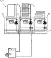
- FIG. 1 shows a known heating system with a boiler 1 and a heating circuit manifold 6 with a non-mixed heating circuit 2 and two weather-compensated heating circuits 3 with mixer 7.
- the heating circuits are equipped with self-regulating pumps 8 and a hydraulic switch 5 below the distributor.
- the purpose of the hydraulic diverter 5 is that the distributor 6 becomes low differential pressure, and the heating circuits 2, 3 influence each other less.
- the heating circuit pumps are easy to adjust and save energy during operation.
- the disadvantage is that a further pump, the boiler pump 4, is required. If it fails, the entire heat supply of the building fails.
- the lack of adjustment of the volume flows above and below the hydraulic separator ensures that the return is usually mixed with hot water from the flow. This increases the fuel consumption of the heat generator, such as heat pump or condensing boiler, whose efficiency is significantly influenced by the return temperature.
- FIG. 2 shows the system according to the invention with a boiler 1 and a heating circuit manifold 6 with a non-mixed heating circuit 2 and two weather-compensated heating circuits 3 with mixer.
- the pumps do not regulate themselves, but are influenced by a controller 11 in their speed. Connected to the controller are the differential pressure sensors 10, and the variable-speed pumps 8. The controller also has the volume flow signal of the pump connected.
- two temperature sensors are connected to the controller.
- the controllers 11 are interconnected via a bus connection 12 with each other.
- the inventive method allows by appropriate control of the pump only spend as much energy or pressure as is needed for the supply. This allows both a power-saving operation of the pumps and achieves a low return temperature by omitting the hydraulic switch. Furthermore, in case of failure of a pump continues to heat supply of building parts.
- FIG. 3 shows a heating system with a boiler 1 and a Schuffyverteiler 6 with a Bank Vietnamesepaktmodul without mixer 13 for the storage load and two Schu Vietnamesepaktmodule with motorized mixer 14 for a radiator circuit and a réellegeber Vietnamese.
- the industrially prefabricated assemblies bring the installer a great deal of time during installation, but also when ordering.
- various stored setpoint values for the differential pressure in the controller are selected. This makes the installation easier for the installer.
- For a floor heating circuit For example, 150 mbar is stored, while for a radiator heating circuit 100 mbar are stored.
Landscapes
- Engineering & Computer Science (AREA)
- Physics & Mathematics (AREA)
- Thermal Sciences (AREA)
- Chemical & Material Sciences (AREA)
- Combustion & Propulsion (AREA)
- Mechanical Engineering (AREA)
- General Engineering & Computer Science (AREA)
- Steam Or Hot-Water Central Heating Systems (AREA)
- Flow Control (AREA)
Applications Claiming Priority (1)
| Application Number | Priority Date | Filing Date | Title |
|---|---|---|---|
| DE102015006779.6A DE102015006779A1 (de) | 2015-06-01 | 2015-06-01 | Verfahren zum Betreiben einer Heizungsanlage und Regler mit Differenzdrucksensor |
Publications (2)
| Publication Number | Publication Date |
|---|---|
| EP3101352A1 EP3101352A1 (de) | 2016-12-07 |
| EP3101352B1 true EP3101352B1 (de) | 2017-06-28 |
Family
ID=56344968
Family Applications (1)
| Application Number | Title | Priority Date | Filing Date |
|---|---|---|---|
| EP16172083.4A Active EP3101352B1 (de) | 2015-06-01 | 2016-05-31 | Verfahren zum betreiben einer heizungsanlage und regler mit differenzdrucksensor |
Country Status (3)
| Country | Link |
|---|---|
| EP (1) | EP3101352B1 (da) |
| DE (1) | DE102015006779A1 (da) |
| DK (1) | DK3101352T3 (da) |
Families Citing this family (6)
| Publication number | Priority date | Publication date | Assignee | Title |
|---|---|---|---|---|
| DE102017115231A1 (de) * | 2017-07-07 | 2019-01-10 | Rehau Ag + Co | Verfahren zur Zuordnung eines Heizkreis-Temperaturfühlers eines Heiz- und/oder Kühlsystems zum betreffenden Heizkreis oder zur Überprüfung der Zuordnung eines Heizkreis-Temperaturfühlers eines Heiz- und/oder Kühlsystems zum betreffenden Heizkreis |
| EP3546840A3 (de) * | 2018-03-30 | 2020-05-27 | Bosch Termoteknik Isitma ve Klima Sanayi Ticaret Anonim Sirketi | Warmwasserbereiter |
| PT110846A (pt) * | 2018-07-13 | 2020-01-13 | Bosch Termotecnologia Sa | Processo para a operação de um sistema de aquecimento e sistema de aquecimento. |
| DE102021101965A1 (de) * | 2021-01-28 | 2022-07-28 | Viessmann Climate Solutions Se | Heizungsanlage und Verfahren zum Betrieb einer Heizungsanlage |
| DE102023106708A1 (de) * | 2023-03-17 | 2024-09-19 | Vaillant Gmbh | Verfahren zur Inbetriebnahme einer Pumpenbaugruppe, Computerprogramm, Regel- und Steuergerät und Heizgerät |
| EP4556800A1 (en) | 2023-11-20 | 2025-05-21 | BDR Thermea Group B.V. | Hydronic balancing mode in a multi-source heating system |
Family Cites Families (8)
| Publication number | Priority date | Publication date | Assignee | Title |
|---|---|---|---|---|
| DE2946049A1 (de) | 1979-11-15 | 1981-05-27 | Hoechst Ag, 6000 Frankfurt | Verfahren zum regeln des durchflusses von kreiselpumpen |
| DE3402120A1 (de) | 1984-01-23 | 1985-07-25 | Rheinhütte vorm. Ludwig Beck GmbH & Co, 6200 Wiesbaden | Verfahren und vorrichtung zur regelung verschiedener betriebsparameter bei pumpen und verdichtern |
| DE19504232A1 (de) | 1995-02-09 | 1996-08-22 | Grundfos As | Verfahren zur Leistungsbegrenzung von elektrisch angetriebenen Heizungsumwälzpumpen |
| DE19842174A1 (de) * | 1998-09-15 | 2000-03-16 | Wilo Gmbh | Pumpenregelung |
| DE10139510B4 (de) * | 2001-08-10 | 2006-10-19 | Robert Bosch Gmbh | Verfahren zur Regelung der Drehzahl einer Umwälzpumpe |
| DE102006054893A1 (de) * | 2006-11-20 | 2008-05-21 | Wilo Ag | Kompaktheizungsanlage |
| DE102008004126B4 (de) * | 2008-01-11 | 2018-01-04 | Rolf Schulze | Verfahren zur Regelung der Kosten in Wärmeverteilungsanlagen |
| DE102013003933A1 (de) * | 2013-03-08 | 2014-09-11 | Paw Gmbh & Co. Kg | Vorrichtung zum Heizen von Räumen,umfaasend zumindest eine zentrale Wärmequelle und umfassend den Räumen zugeordnete Heizkreise |
-
2015
- 2015-06-01 DE DE102015006779.6A patent/DE102015006779A1/de not_active Withdrawn
-
2016
- 2016-05-31 DK DK16172083.4T patent/DK3101352T3/da active
- 2016-05-31 EP EP16172083.4A patent/EP3101352B1/de active Active
Non-Patent Citations (1)
| Title |
|---|
| None * |
Also Published As
| Publication number | Publication date |
|---|---|
| EP3101352A1 (de) | 2016-12-07 |
| DK3101352T3 (da) | 2017-10-09 |
| DE102015006779A1 (de) | 2016-12-01 |
Similar Documents
| Publication | Publication Date | Title |
|---|---|---|
| EP3101352B1 (de) | Verfahren zum betreiben einer heizungsanlage und regler mit differenzdrucksensor | |
| EP3593055B1 (de) | Verfahren zum betreiben einer heizungsanlage | |
| DE69709715T2 (de) | Verfahren und einrichtung zur temperaturregelung von heissem brauchwasser | |
| EP2187136A2 (de) | Verfahren zum Betreiben eines Systems zum Transport thermischer Energie über ein flüssiges Medium | |
| DE102015121418B3 (de) | Verfahren zum automatischen hydraulischen Abgleich von Verbrauchern in einer Heizungs- und/oder Kühlanlage | |
| EP2863134B1 (de) | Verfahren zum Anpassen einer Heizkurve | |
| DE102007010768A1 (de) | Verfahren für die Optimierung der Ventilstellung und der Pumpendrehzahl in einem Ventilsystem mit PID-Regelung ohne die Verwendung externer Signale | |
| DE102014016791B4 (de) | Verfahren zur hydraulischen Regelung mehrerer Heizkreisläufe am Verteilerbalken | |
| EP3473939B1 (de) | Verfahren zum betreiben einer heizungsanlage und heizungsanlage | |
| EP2636959B1 (de) | Heizkörperregelung | |
| EP3217101A1 (de) | Verfahren zur hydraulischen entkopplung mehrerer, parallel geschalteter fluidkreisläufe | |
| AT406081B (de) | Heizanlage | |
| EP3412978B1 (de) | Verfahren zur steuerung eines heiz- und/oder kühlsystems | |
| EP3919823A1 (de) | Verfahren zur steuerung der wärmeerzeugung und -verteilung in einer heizungsanlage | |
| EP1191287A2 (de) | Leitungssystem zur thermischen Energieübertragung | |
| DE102014202738A1 (de) | Verfahren zum automatisierten hydraulischen Abgleich einer Heinzungsanlage | |
| EP1310746B1 (de) | Vorrichtung und Verfahren zur Regelung von Thermen | |
| EP4015918B1 (de) | Verfahren zur ansteuerung eines primärkreises einer heizungsanlage und heizungsanlage | |
| DE10144595A1 (de) | Zentralheizungsanlage | |
| EP3369934B1 (de) | Umwälzpumpenaggregat | |
| DE102005040792B3 (de) | Selbstlernender Temperaturregler | |
| EP1321842B1 (de) | Hydraulische Anlage | |
| EP4549822A1 (de) | Verfahren zum betreiben einer heizungsanlage, heizungsanlage und computerprogramm | |
| EP4509769A1 (de) | Verfahren zur einstellung eines überströmventils für einen heizsystem | |
| WO2025114874A1 (de) | Regelung der steilheit einer heizungskurve |
Legal Events
| Date | Code | Title | Description |
|---|---|---|---|
| PUAI | Public reference made under article 153(3) epc to a published international application that has entered the european phase |
Free format text: ORIGINAL CODE: 0009012 |
|
| AK | Designated contracting states |
Kind code of ref document: A1 Designated state(s): AL AT BE BG CH CY CZ DE DK EE ES FI FR GB GR HR HU IE IS IT LI LT LU LV MC MK MT NL NO PL PT RO RS SE SI SK SM TR |
|
| AX | Request for extension of the european patent |
Extension state: BA ME |
|
| 17P | Request for examination filed |
Effective date: 20161215 |
|
| RBV | Designated contracting states (corrected) |
Designated state(s): AL AT BE BG CH CY CZ DE DK EE ES FI FR GB GR HR HU IE IS IT LI LT LU LV MC MK MT NL NO PL PT RO RS SE SI SK SM TR |
|
| GRAP | Despatch of communication of intention to grant a patent |
Free format text: ORIGINAL CODE: EPIDOSNIGR1 |
|
| INTG | Intention to grant announced |
Effective date: 20170329 |
|
| GRAS | Grant fee paid |
Free format text: ORIGINAL CODE: EPIDOSNIGR3 |
|
| GRAA | (expected) grant |
Free format text: ORIGINAL CODE: 0009210 |
|
| AK | Designated contracting states |
Kind code of ref document: B1 Designated state(s): AL AT BE BG CH CY CZ DE DK EE ES FI FR GB GR HR HU IE IS IT LI LT LU LV MC MK MT NL NO PL PT RO RS SE SI SK SM TR |
|
| REG | Reference to a national code |
Ref country code: GB Ref legal event code: FG4D Free format text: NOT ENGLISH |
|
| REG | Reference to a national code |
Ref country code: CH Ref legal event code: EP |
|
| REG | Reference to a national code |
Ref country code: AT Ref legal event code: REF Ref document number: 905224 Country of ref document: AT Kind code of ref document: T Effective date: 20170715 |
|
| REG | Reference to a national code |
Ref country code: IE Ref legal event code: FG4D Free format text: LANGUAGE OF EP DOCUMENT: GERMAN |
|
| REG | Reference to a national code |
Ref country code: DE Ref legal event code: R096 Ref document number: 502016000046 Country of ref document: DE |
|
| REG | Reference to a national code |
Ref country code: CH Ref legal event code: NV Representative=s name: PATENTANWAELTE SCHAAD, BALASS, MENZL AND PARTN, CH |
|
| REG | Reference to a national code |
Ref country code: DK Ref legal event code: T3 Effective date: 20171006 |
|
| PG25 | Lapsed in a contracting state [announced via postgrant information from national office to epo] |
Ref country code: GR Free format text: LAPSE BECAUSE OF FAILURE TO SUBMIT A TRANSLATION OF THE DESCRIPTION OR TO PAY THE FEE WITHIN THE PRESCRIBED TIME-LIMIT Effective date: 20170929 Ref country code: FI Free format text: LAPSE BECAUSE OF FAILURE TO SUBMIT A TRANSLATION OF THE DESCRIPTION OR TO PAY THE FEE WITHIN THE PRESCRIBED TIME-LIMIT Effective date: 20170628 Ref country code: NO Free format text: LAPSE BECAUSE OF FAILURE TO SUBMIT A TRANSLATION OF THE DESCRIPTION OR TO PAY THE FEE WITHIN THE PRESCRIBED TIME-LIMIT Effective date: 20170928 Ref country code: HR Free format text: LAPSE BECAUSE OF FAILURE TO SUBMIT A TRANSLATION OF THE DESCRIPTION OR TO PAY THE FEE WITHIN THE PRESCRIBED TIME-LIMIT Effective date: 20170628 Ref country code: LT Free format text: LAPSE BECAUSE OF FAILURE TO SUBMIT A TRANSLATION OF THE DESCRIPTION OR TO PAY THE FEE WITHIN THE PRESCRIBED TIME-LIMIT Effective date: 20170628 |
|
| REG | Reference to a national code |
Ref country code: NL Ref legal event code: MP Effective date: 20170628 |
|
| REG | Reference to a national code |
Ref country code: LT Ref legal event code: MG4D |
|
| PG25 | Lapsed in a contracting state [announced via postgrant information from national office to epo] |
Ref country code: SE Free format text: LAPSE BECAUSE OF FAILURE TO SUBMIT A TRANSLATION OF THE DESCRIPTION OR TO PAY THE FEE WITHIN THE PRESCRIBED TIME-LIMIT Effective date: 20170628 Ref country code: NL Free format text: LAPSE BECAUSE OF FAILURE TO SUBMIT A TRANSLATION OF THE DESCRIPTION OR TO PAY THE FEE WITHIN THE PRESCRIBED TIME-LIMIT Effective date: 20170628 Ref country code: RS Free format text: LAPSE BECAUSE OF FAILURE TO SUBMIT A TRANSLATION OF THE DESCRIPTION OR TO PAY THE FEE WITHIN THE PRESCRIBED TIME-LIMIT Effective date: 20170628 Ref country code: LV Free format text: LAPSE BECAUSE OF FAILURE TO SUBMIT A TRANSLATION OF THE DESCRIPTION OR TO PAY THE FEE WITHIN THE PRESCRIBED TIME-LIMIT Effective date: 20170628 Ref country code: BG Free format text: LAPSE BECAUSE OF FAILURE TO SUBMIT A TRANSLATION OF THE DESCRIPTION OR TO PAY THE FEE WITHIN THE PRESCRIBED TIME-LIMIT Effective date: 20170928 |
|
| PG25 | Lapsed in a contracting state [announced via postgrant information from national office to epo] |
Ref country code: SK Free format text: LAPSE BECAUSE OF FAILURE TO SUBMIT A TRANSLATION OF THE DESCRIPTION OR TO PAY THE FEE WITHIN THE PRESCRIBED TIME-LIMIT Effective date: 20170628 Ref country code: EE Free format text: LAPSE BECAUSE OF FAILURE TO SUBMIT A TRANSLATION OF THE DESCRIPTION OR TO PAY THE FEE WITHIN THE PRESCRIBED TIME-LIMIT Effective date: 20170628 Ref country code: CZ Free format text: LAPSE BECAUSE OF FAILURE TO SUBMIT A TRANSLATION OF THE DESCRIPTION OR TO PAY THE FEE WITHIN THE PRESCRIBED TIME-LIMIT Effective date: 20170628 |
|
| PG25 | Lapsed in a contracting state [announced via postgrant information from national office to epo] |
Ref country code: IS Free format text: LAPSE BECAUSE OF FAILURE TO SUBMIT A TRANSLATION OF THE DESCRIPTION OR TO PAY THE FEE WITHIN THE PRESCRIBED TIME-LIMIT Effective date: 20171028 Ref country code: PL Free format text: LAPSE BECAUSE OF FAILURE TO SUBMIT A TRANSLATION OF THE DESCRIPTION OR TO PAY THE FEE WITHIN THE PRESCRIBED TIME-LIMIT Effective date: 20170628 Ref country code: SM Free format text: LAPSE BECAUSE OF FAILURE TO SUBMIT A TRANSLATION OF THE DESCRIPTION OR TO PAY THE FEE WITHIN THE PRESCRIBED TIME-LIMIT Effective date: 20170628 Ref country code: ES Free format text: LAPSE BECAUSE OF FAILURE TO SUBMIT A TRANSLATION OF THE DESCRIPTION OR TO PAY THE FEE WITHIN THE PRESCRIBED TIME-LIMIT Effective date: 20170628 |
|
| REG | Reference to a national code |
Ref country code: DE Ref legal event code: R097 Ref document number: 502016000046 Country of ref document: DE |
|
| PLBE | No opposition filed within time limit |
Free format text: ORIGINAL CODE: 0009261 |
|
| STAA | Information on the status of an ep patent application or granted ep patent |
Free format text: STATUS: NO OPPOSITION FILED WITHIN TIME LIMIT |
|
| REG | Reference to a national code |
Ref country code: FR Ref legal event code: PLFP Year of fee payment: 3 |
|
| 26N | No opposition filed |
Effective date: 20180329 |
|
| PG25 | Lapsed in a contracting state [announced via postgrant information from national office to epo] |
Ref country code: SI Free format text: LAPSE BECAUSE OF FAILURE TO SUBMIT A TRANSLATION OF THE DESCRIPTION OR TO PAY THE FEE WITHIN THE PRESCRIBED TIME-LIMIT Effective date: 20170628 |
|
| PG25 | Lapsed in a contracting state [announced via postgrant information from national office to epo] |
Ref country code: MT Free format text: LAPSE BECAUSE OF FAILURE TO SUBMIT A TRANSLATION OF THE DESCRIPTION OR TO PAY THE FEE WITHIN THE PRESCRIBED TIME-LIMIT Effective date: 20170628 |
|
| PG25 | Lapsed in a contracting state [announced via postgrant information from national office to epo] |
Ref country code: MC Free format text: LAPSE BECAUSE OF FAILURE TO SUBMIT A TRANSLATION OF THE DESCRIPTION OR TO PAY THE FEE WITHIN THE PRESCRIBED TIME-LIMIT Effective date: 20170628 |
|
| REG | Reference to a national code |
Ref country code: IE Ref legal event code: MM4A |
|
| PG25 | Lapsed in a contracting state [announced via postgrant information from national office to epo] |
Ref country code: LU Free format text: LAPSE BECAUSE OF NON-PAYMENT OF DUE FEES Effective date: 20180531 |
|
| PG25 | Lapsed in a contracting state [announced via postgrant information from national office to epo] |
Ref country code: IE Free format text: LAPSE BECAUSE OF NON-PAYMENT OF DUE FEES Effective date: 20180531 |
|
| PG25 | Lapsed in a contracting state [announced via postgrant information from national office to epo] |
Ref country code: TR Free format text: LAPSE BECAUSE OF FAILURE TO SUBMIT A TRANSLATION OF THE DESCRIPTION OR TO PAY THE FEE WITHIN THE PRESCRIBED TIME-LIMIT Effective date: 20170628 |
|
| PG25 | Lapsed in a contracting state [announced via postgrant information from national office to epo] |
Ref country code: PT Free format text: LAPSE BECAUSE OF FAILURE TO SUBMIT A TRANSLATION OF THE DESCRIPTION OR TO PAY THE FEE WITHIN THE PRESCRIBED TIME-LIMIT Effective date: 20170628 |
|
| PG25 | Lapsed in a contracting state [announced via postgrant information from national office to epo] |
Ref country code: RO Free format text: LAPSE BECAUSE OF FAILURE TO SUBMIT A TRANSLATION OF THE DESCRIPTION OR TO PAY THE FEE WITHIN THE PRESCRIBED TIME-LIMIT Effective date: 20170628 Ref country code: MK Free format text: LAPSE BECAUSE OF NON-PAYMENT OF DUE FEES Effective date: 20170628 Ref country code: HU Free format text: LAPSE BECAUSE OF FAILURE TO SUBMIT A TRANSLATION OF THE DESCRIPTION OR TO PAY THE FEE WITHIN THE PRESCRIBED TIME-LIMIT; INVALID AB INITIO Effective date: 20160531 Ref country code: CY Free format text: LAPSE BECAUSE OF FAILURE TO SUBMIT A TRANSLATION OF THE DESCRIPTION OR TO PAY THE FEE WITHIN THE PRESCRIBED TIME-LIMIT Effective date: 20170628 |
|
| PG25 | Lapsed in a contracting state [announced via postgrant information from national office to epo] |
Ref country code: AL Free format text: LAPSE BECAUSE OF FAILURE TO SUBMIT A TRANSLATION OF THE DESCRIPTION OR TO PAY THE FEE WITHIN THE PRESCRIBED TIME-LIMIT Effective date: 20170628 |
|
| P01 | Opt-out of the competence of the unified patent court (upc) registered |
Effective date: 20230601 |
|
| PGFP | Annual fee paid to national office [announced via postgrant information from national office to epo] |
Ref country code: DE Payment date: 20250430 Year of fee payment: 10 |
|
| PGFP | Annual fee paid to national office [announced via postgrant information from national office to epo] |
Ref country code: GB Payment date: 20250508 Year of fee payment: 10 Ref country code: DK Payment date: 20250521 Year of fee payment: 10 |
|
| PGFP | Annual fee paid to national office [announced via postgrant information from national office to epo] |
Ref country code: BE Payment date: 20250520 Year of fee payment: 10 Ref country code: IT Payment date: 20250530 Year of fee payment: 10 |
|
| PGFP | Annual fee paid to national office [announced via postgrant information from national office to epo] |
Ref country code: FR Payment date: 20250521 Year of fee payment: 10 |
|
| PGFP | Annual fee paid to national office [announced via postgrant information from national office to epo] |
Ref country code: CH Payment date: 20250601 Year of fee payment: 10 |
|
| PGFP | Annual fee paid to national office [announced via postgrant information from national office to epo] |
Ref country code: AT Payment date: 20250519 Year of fee payment: 10 |