EP3101358A1 - Dispositif destine a influencer la climatisation - Google Patents
Dispositif destine a influencer la climatisation Download PDFInfo
- Publication number
- EP3101358A1 EP3101358A1 EP16170195.8A EP16170195A EP3101358A1 EP 3101358 A1 EP3101358 A1 EP 3101358A1 EP 16170195 A EP16170195 A EP 16170195A EP 3101358 A1 EP3101358 A1 EP 3101358A1
- Authority
- EP
- European Patent Office
- Prior art keywords
- room
- control unit
- climate
- battery compartment
- power supply
- Prior art date
- Legal status (The legal status is an assumption and is not a legal conclusion. Google has not performed a legal analysis and makes no representation as to the accuracy of the status listed.)
- Withdrawn
Links
Images




Classifications
-
- F—MECHANICAL ENGINEERING; LIGHTING; HEATING; WEAPONS; BLASTING
- F24—HEATING; RANGES; VENTILATING
- F24F—AIR-CONDITIONING; AIR-HUMIDIFICATION; VENTILATION; USE OF AIR CURRENTS FOR SCREENING
- F24F11/00—Control or safety arrangements
- F24F11/30—Control or safety arrangements for purposes related to the operation of the system, e.g. for safety or monitoring
-
- F—MECHANICAL ENGINEERING; LIGHTING; HEATING; WEAPONS; BLASTING
- F24—HEATING; RANGES; VENTILATING
- F24F—AIR-CONDITIONING; AIR-HUMIDIFICATION; VENTILATION; USE OF AIR CURRENTS FOR SCREENING
- F24F11/00—Control or safety arrangements
- F24F11/30—Control or safety arrangements for purposes related to the operation of the system, e.g. for safety or monitoring
- F24F11/46—Improving electric energy efficiency or saving
-
- F—MECHANICAL ENGINEERING; LIGHTING; HEATING; WEAPONS; BLASTING
- F24—HEATING; RANGES; VENTILATING
- F24F—AIR-CONDITIONING; AIR-HUMIDIFICATION; VENTILATION; USE OF AIR CURRENTS FOR SCREENING
- F24F11/00—Control or safety arrangements
- F24F11/50—Control or safety arrangements characterised by user interfaces or communication
- F24F11/52—Indication arrangements, e.g. displays
- F24F11/523—Indication arrangements, e.g. displays for displaying temperature data
-
- F—MECHANICAL ENGINEERING; LIGHTING; HEATING; WEAPONS; BLASTING
- F24—HEATING; RANGES; VENTILATING
- F24F—AIR-CONDITIONING; AIR-HUMIDIFICATION; VENTILATION; USE OF AIR CURRENTS FOR SCREENING
- F24F11/00—Control or safety arrangements
- F24F11/50—Control or safety arrangements characterised by user interfaces or communication
- F24F11/56—Remote control
-
- F—MECHANICAL ENGINEERING; LIGHTING; HEATING; WEAPONS; BLASTING
- F24—HEATING; RANGES; VENTILATING
- F24F—AIR-CONDITIONING; AIR-HUMIDIFICATION; VENTILATION; USE OF AIR CURRENTS FOR SCREENING
- F24F11/00—Control or safety arrangements
- F24F11/62—Control or safety arrangements characterised by the type of control or by internal processing, e.g. using fuzzy logic, adaptive control or estimation of values
-
- F—MECHANICAL ENGINEERING; LIGHTING; HEATING; WEAPONS; BLASTING
- F24—HEATING; RANGES; VENTILATING
- F24F—AIR-CONDITIONING; AIR-HUMIDIFICATION; VENTILATION; USE OF AIR CURRENTS FOR SCREENING
- F24F11/00—Control or safety arrangements
- F24F11/62—Control or safety arrangements characterised by the type of control or by internal processing, e.g. using fuzzy logic, adaptive control or estimation of values
- F24F11/63—Electronic processing
-
- F—MECHANICAL ENGINEERING; LIGHTING; HEATING; WEAPONS; BLASTING
- F24—HEATING; RANGES; VENTILATING
- F24F—AIR-CONDITIONING; AIR-HUMIDIFICATION; VENTILATION; USE OF AIR CURRENTS FOR SCREENING
- F24F11/00—Control or safety arrangements
- F24F11/70—Control systems characterised by their outputs; Constructional details thereof
- F24F11/80—Control systems characterised by their outputs; Constructional details thereof for controlling the temperature of the supplied air
- F24F11/83—Control systems characterised by their outputs; Constructional details thereof for controlling the temperature of the supplied air by controlling the supply of heat-exchange fluids to heat-exchangers
- F24F11/84—Control systems characterised by their outputs; Constructional details thereof for controlling the temperature of the supplied air by controlling the supply of heat-exchange fluids to heat-exchangers using valves
-
- F—MECHANICAL ENGINEERING; LIGHTING; HEATING; WEAPONS; BLASTING
- F24—HEATING; RANGES; VENTILATING
- F24F—AIR-CONDITIONING; AIR-HUMIDIFICATION; VENTILATION; USE OF AIR CURRENTS FOR SCREENING
- F24F11/00—Control or safety arrangements
- F24F11/50—Control or safety arrangements characterised by user interfaces or communication
- F24F11/52—Indication arrangements, e.g. displays
-
- F—MECHANICAL ENGINEERING; LIGHTING; HEATING; WEAPONS; BLASTING
- F24—HEATING; RANGES; VENTILATING
- F24F—AIR-CONDITIONING; AIR-HUMIDIFICATION; VENTILATION; USE OF AIR CURRENTS FOR SCREENING
- F24F11/00—Control or safety arrangements
- F24F11/70—Control systems characterised by their outputs; Constructional details thereof
- F24F11/80—Control systems characterised by their outputs; Constructional details thereof for controlling the temperature of the supplied air
- F24F11/83—Control systems characterised by their outputs; Constructional details thereof for controlling the temperature of the supplied air by controlling the supply of heat-exchange fluids to heat-exchangers
-
- F—MECHANICAL ENGINEERING; LIGHTING; HEATING; WEAPONS; BLASTING
- F24—HEATING; RANGES; VENTILATING
- F24F—AIR-CONDITIONING; AIR-HUMIDIFICATION; VENTILATION; USE OF AIR CURRENTS FOR SCREENING
- F24F2110/00—Control inputs relating to air properties
- F24F2110/10—Temperature
Definitions
- the invention relates to a device for influencing the indoor climate in heated or air-conditioned spaces.
- climate meters are also known, which indicate a ventilation requirement based on the measured data by comparing the measured values with setpoints.
- indoor climate systems are known in which the windows of the room are opened or closed by means of motor drives. Such a configuration can be retrofitted only at great expense.
- indoor climate control devices which not only indicate the ventilation requirement via manual window ventilation, but also actuate a ventilation system with or without heat recovery. Even such systems are extremely complex and correspondingly expensive to buy. A retrofitting of existing premises is associated with high costs.
- Systems are also known in which the heating or cooling source is reduced in power or switched off. For example, such systems have integrated electronic contacts on the windows, so that they both over Temperature measurement can also be controlled via the electronic contact when opening / closing the windows. Even such systems require extremely costly measures.
- wired window contacts which pass on the signal of the window open detection to a room temperature controller for a forced reduction in room temperature, require a high installation effort, which is extremely unfavorable, above all because of structural interventions in the aftermarket business.
- the present invention seeks to provide a device of the generic type, which provides a low cost with respect to purchase, installation and operation, a comfortable operation option, the indoor climate in heated or air-conditioned spaces while avoiding unnecessary energy losses influence and extend the scope of application in the room air conditioning by simple retrofit option.
- Such a device combines the measurement and display of room climate values with the control of the room temperature and allows visualization and adjustment of all room climate values via just one display and user interface.
- room climate data can be evaluated directly and used for room temperature control, so that when performing Ventilation unnecessary energy losses are avoided.
- controllable electronic actuator has inputs and outputs for data communication with the room control unit, the transmitted from the room control unit values
- To control the electronic actuator can here directly take into account information from the evaluation of the room climate parameters.
- a significant advantage is achieved to display the room climate and to improve it by incorporating simplified ventilation measures, such as window ventilation, and to reduce heating and / or cooling energy losses during these ventilation measures, the device of an electronic room control unit, the room climate data such as carbon dioxide, humidity, odors and temperature via their own sensors measures and / or received from external sensors, displays, evaluates and provides these via outputs for data communication, and a control device for the room temperature and with an addressable by the control device electronic Actuator for Valves for setting a volume flow in a heating or cooling system communicates.
- simplified ventilation measures such as window ventilation
- the device of an electronic room control unit the room climate data such as carbon dioxide, humidity, odors and temperature via their own sensors measures and / or received from external sensors
- displays evaluates and provides these via outputs for data communication
- An advantageous embodiment of the device results in terms of their energy supply by the optional equipment with batteries or the connection to a power grid.
- the installation effort can be further reduced on the other hand, using the same device and a supply can be retrofitted via the mains.
- the room control unit has a battery compartment for energy supply via batteries, which can be closed with a cover plate, and which is designed for power supply via the power grid, the cover plate as a power supply or connected via a power cable with such a , With such accessories, the room control unit can be converted from battery supply to mains power supply very quickly and at low cost, without having to make any further changes to the room control unit.
- a preferred application of the cover results when this forms the back of the room control unit and is designed as a stand for a table installation or as a wall bracket.
- a particular advantageous design of the room control unit arises in the case of supply via the power grid, since then the interior of the battery compartment remains free and can be integrated in these additional components for functional extensions of the device for displaying the indoor environment.
- a preferred application results from the use of a sensor for detecting the carbon dioxide content CO 2 of the room air, which is connected to an electronic board, housed as a unit in the interior of the battery compartment and closed by the cover plate.
- a particularly advantageous functional extension is obtained by recording the temporal changes of indoor climate data with which gradients can be formed and used for influencing the room climate values.
- this gradient is formed from measured CO2 values, then this can be used advantageously by the room control unit for controlling the energy supply for space heating and / or room air conditioning.
- the gradient formation is triggered in a suitable manner by a manual ventilation measure, eg window ventilation, since when opening the window, a high CO2 content in the room air falls very quickly. Conversely, this increases again when the window is closed. Since in the meantime the power supply for heating or cooling means unnecessary power consumption, the gradient is used as a signal for shutting down the heating or cooling system.
- a manual ventilation measure eg window ventilation
- the FIG. 1 shows a schematic representation of an arranged in a space device for displaying room climate values.
- the window F represents a manual ventilation device.
- the device consists of an electronic room control unit 1, which measures indoor climate data with its own sensors or receives transmitted from external sensors, evaluates and provides via outputs (eg wireless sensor) for data communication.
- outputs eg wireless sensor
- a control device for the room temperature is integrated.
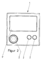
- the front side of the cuboid room operating unit 1 has a display 1 'which displays data measured by sensors, for example temperature, carbon dioxide content, relative humidity.
- a display 1 ' which displays data measured by sensors, for example temperature, carbon dioxide content, relative humidity.
- corresponding electronic sensors are arranged, which are connected via an electronic intelligence, for example a data memory and / or a processor unit, to one another and to the display means of the display 1 '.
- the electronic intelligence communicates with a transmitter integrated in the device, e.g. a radio transmitter, by means of which of the control device, which is also integrated in the device, control signals are generated, which are used to set a controllable electric actuator S, for example, a heating or cooling body H.
- the corresponding electronic components are in data communication via corresponding inputs and outputs.
- FIG. 2 shows the controls 2 of the control device with which settings, for example, made of setpoints or time intervals can be programmed, which can be stored and / or processed, for example, in an electronic memory, which is housed in the device housing.
- Another component of the device for displaying room climate values is an electronic actuator 3 for valves V that can be controlled by the room control unit and which is located in the room temperature control unit Embodiment for adjusting the volume flow to a radiator H is mounted.
- the actuator In order to receive positioning commands and to send position reports, the actuator has inputs and outputs for data communication, in particular with the wireless sensor of the room control unit. 1
- the room control unit 1 can be operated via batteries or via the mains.
- FIG. 3 shows a battery compartment 4 on the back 5 of the room control unit 1.
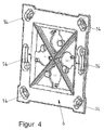
- the battery compartment 4 by a in the FIG. 4 Cover plate 6 shown closed, which also forms the rear wall of the room control unit 1 and is inserted according to tongue and groove principle in the housing of the room control unit 1.
- contacts 7 are arranged, which are contacted in the case of power supply via the mains by the associated opposite contacts 8 a cover plate, see FIG. 5 ,
- This cover plate 6 in this case has a power cable S, which has a power connection z. B. to a power supply unit manufactures. It also forms the back wall of the room control unit. 1
- Both versions of the cover plate 6 additionally have elements 14 for both
- Wall mounting as well as for mounting to a flush-mounted box.
- a third version of the cover plate 6 shows the FIG. 6 in which it is designed as a stand 9 for free placement, eg on a table.
- a fourth version, not shown here also has the contacts described above and a power cable.
- a special feature of the invention is in the FIG. 7 specified. If the room control unit 1 is supplied with power via the power grid, no batteries are required, so that the interior 10 of the battery compartment 11 remains free.
- the components may advantageously be sensors or actuators which serve to record the quality of the room air, in particular they may be CO2 sensors.
- the room control unit 1 also accommodates the control device for the room temperature and, as described above, further indoor climate values such as the carbon dioxide content of the room air can be detected, there is a further special feature.
- This is the time change of at least one room climate value by forming a gradient by an electronics of the room control unit 1 and described this gradient used for influencing the room or the room climate values.
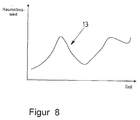
- FIG. 8 is exemplified such a time course 13 of a room climate value.
- a gradient that results, for example, in a decrease in the room climate size, can be used for an intervention in the regulation of the room temperature.
- the gradient thus formed can be used to lower the energy supply of the heating or cooling system in order to save energy during the ventilation phase.
- the gradient formed by the increasing course of the CO2 content can be used to reactivate the energy supply.
Landscapes
- Engineering & Computer Science (AREA)
- Chemical & Material Sciences (AREA)
- Combustion & Propulsion (AREA)
- Mechanical Engineering (AREA)
- General Engineering & Computer Science (AREA)
- Signal Processing (AREA)
- Physics & Mathematics (AREA)
- Fuzzy Systems (AREA)
- Mathematical Physics (AREA)
- Human Computer Interaction (AREA)
- Air Conditioning Control Device (AREA)
Applications Claiming Priority (2)
| Application Number | Priority Date | Filing Date | Title |
|---|---|---|---|
| DE102013101684.7A DE102013101684A1 (de) | 2013-02-20 | 2013-02-20 | Vorrichtung zur Beeinflussung des Raumklimas |
| EP14716749.8A EP2959233A1 (fr) | 2013-02-20 | 2014-02-19 | Dispositif permettant d'influer sur la climatisation d'un local |
Related Parent Applications (1)
| Application Number | Title | Priority Date | Filing Date |
|---|---|---|---|
| EP14716749.8A Division EP2959233A1 (fr) | 2013-02-20 | 2014-02-19 | Dispositif permettant d'influer sur la climatisation d'un local |
Publications (1)
| Publication Number | Publication Date |
|---|---|
| EP3101358A1 true EP3101358A1 (fr) | 2016-12-07 |
Family
ID=50478640
Family Applications (2)
| Application Number | Title | Priority Date | Filing Date |
|---|---|---|---|
| EP14716749.8A Withdrawn EP2959233A1 (fr) | 2013-02-20 | 2014-02-19 | Dispositif permettant d'influer sur la climatisation d'un local |
| EP16170195.8A Withdrawn EP3101358A1 (fr) | 2013-02-20 | 2014-02-19 | Dispositif destine a influencer la climatisation |
Family Applications Before (1)
| Application Number | Title | Priority Date | Filing Date |
|---|---|---|---|
| EP14716749.8A Withdrawn EP2959233A1 (fr) | 2013-02-20 | 2014-02-19 | Dispositif permettant d'influer sur la climatisation d'un local |
Country Status (6)
| Country | Link |
|---|---|
| US (1) | US20150354848A1 (fr) |
| EP (2) | EP2959233A1 (fr) |
| CN (1) | CN105190189A (fr) |
| DE (1) | DE102013101684A1 (fr) |
| RU (1) | RU2015139894A (fr) |
| WO (1) | WO2014127771A1 (fr) |
Families Citing this family (30)
| Publication number | Priority date | Publication date | Assignee | Title |
|---|---|---|---|---|
| EP2796800B1 (fr) * | 2011-12-20 | 2018-03-21 | Mitsubishi Electric Corporation | Dispositif de commande à distance destiné à un climatiseur |
| GB201513012D0 (en) | 2015-06-11 | 2015-09-09 | Eaton Industires Austria Gmbh | Method for the detection of an open ventilation opening |
| USD811328S1 (en) * | 2015-07-29 | 2018-02-27 | Tbb Power (Xiamen) Co., Ltd. | Power supply remote control |
| US10806177B2 (en) | 2016-09-26 | 2020-10-20 | Erich Linus Birchler | Apparatus and method for monitoring airing events in humidors |
| USD820793S1 (en) * | 2016-11-09 | 2018-06-19 | Mitsubishi Electric Corporation | Remote controller for air conditioner |
| CN118347156A (zh) * | 2017-07-14 | 2024-07-16 | 大金工业株式会社 | 设备控制系统 |
| US10767878B2 (en) | 2017-11-21 | 2020-09-08 | Emerson Climate Technologies, Inc. | Humidifier control systems and methods |
| EP3781879B1 (fr) | 2018-04-20 | 2025-02-12 | Copeland LP | Système de qualité d'air intérieur et procédé de l'opération d' un tel système |
| US12018852B2 (en) | 2018-04-20 | 2024-06-25 | Copeland Comfort Control Lp | HVAC filter usage analysis system |
| EP3781878B1 (fr) | 2018-04-20 | 2024-02-14 | Copeland LP | Système et procédé d'ajustement de seuils d'atténuation |
| US12259148B2 (en) | 2018-04-20 | 2025-03-25 | Copeland Lp | Computerized HVAC filter evaluation system |
| WO2019204779A1 (fr) | 2018-04-20 | 2019-10-24 | Emerson Climate Technologies, Inc. | Systèmes et procédés de surveillance de la qualité de l'air intérieur et de l'occupant |
| US11421901B2 (en) | 2018-04-20 | 2022-08-23 | Emerson Climate Technologies, Inc. | Coordinated control of standalone and building indoor air quality devices and systems |
| US11486593B2 (en) | 2018-04-20 | 2022-11-01 | Emerson Climate Technologies, Inc. | Systems and methods with variable mitigation thresholds |
| WO2019204789A1 (fr) | 2018-04-20 | 2019-10-24 | Emerson Climate Technologies, Inc. | Systèmes et procédés d'étalonnage de capteur de qualité d'air intérieur |
| WO2019204785A1 (fr) | 2018-04-20 | 2019-10-24 | Emerson Climate Technologies, Inc. | Système de commande de ventilateur à base de matière particulaire |
| US11371726B2 (en) | 2018-04-20 | 2022-06-28 | Emerson Climate Technologies, Inc. | Particulate-matter-size-based fan control system |
| USD920261S1 (en) * | 2018-07-20 | 2021-05-25 | Toshiba Carrier Corporation | Remote controller for air conditioner |
| JP1643418S (fr) * | 2018-09-27 | 2019-10-15 | ||
| USD969092S1 (en) | 2019-09-16 | 2022-11-08 | Kohler Co. | Remote control |
| USD972946S1 (en) * | 2019-12-12 | 2022-12-20 | Honeywell International Inc. | Building controller |
| JP1674310S (fr) * | 2020-02-28 | 2020-12-07 | ||
| JP1674311S (fr) * | 2020-02-28 | 2020-12-07 | ||
| EP4036488A1 (fr) * | 2021-01-29 | 2022-08-03 | Siemens Aktiengesellschaft | Procédé et agencement de réglage d'un climat ambiant selon les préférences climatiques des utilisateurs |
| USD991192S1 (en) * | 2021-06-30 | 2023-07-04 | Mitsubishi Electric Corporation | Remote controller for air conditioner |
| JP1738792S (ja) * | 2021-09-30 | 2023-03-10 | 回線制御機器 | |
| JP1743110S (ja) * | 2021-09-30 | 2023-04-28 | 回線制御機器 | |
| CN114868569B (zh) * | 2022-05-27 | 2024-04-16 | 仲恺农业工程学院 | 气候调节方法、装置、系统、电子设备及计算机存储介质 |
| USD1082721S1 (en) | 2023-03-24 | 2025-07-08 | Honeywell International Inc. | Building controller |
| USD1069612S1 (en) | 2023-05-04 | 2025-04-08 | Honeywell International Inc. | Building controller |
Citations (6)
| Publication number | Priority date | Publication date | Assignee | Title |
|---|---|---|---|---|
| US20090140056A1 (en) * | 2007-11-30 | 2009-06-04 | Honeywell International, Inc. | Hvac controller with quick select feature |
| EP2148147A2 (fr) * | 2008-07-22 | 2010-01-27 | Samsung Electronics Co., Ltd. | Procédé de contrôle de climatiseur |
| US20100107071A1 (en) * | 2008-10-27 | 2010-04-29 | Lennox Industries Inc. | System and method of use for a user interface dashboard of a heating, ventilation and air conditioning network |
| US20100163633A1 (en) * | 2008-12-30 | 2010-07-01 | Aquante Llc | Automatically Balancing Register for HVAC Systems |
| EP2354693A2 (fr) * | 2008-09-24 | 2011-08-10 | Toshiba Carrier Corporation | Dispositif d'air conditionné |
| US20120323374A1 (en) * | 2011-06-20 | 2012-12-20 | Honeywell International Inc. | Hvac controller with component change notification |
Family Cites Families (9)
| Publication number | Priority date | Publication date | Assignee | Title |
|---|---|---|---|---|
| US5485954A (en) * | 1994-06-10 | 1996-01-23 | American Standard Inc. | Reduced profile thermostat |
| US6398118B1 (en) * | 1999-01-29 | 2002-06-04 | Howard B. Rosen | Thermostat incorporating thin film carbon dioxide sensor and environmental control system |
| US20030181158A1 (en) * | 2002-01-31 | 2003-09-25 | Edwards Systems Technology, Inc. | Economizer control |
| US7114554B2 (en) * | 2003-12-01 | 2006-10-03 | Honeywell International Inc. | Controller interface with multiple day programming |
| CN101072629B (zh) * | 2004-01-20 | 2010-05-05 | 开利公司 | 供暖、通风与空调系统中的单一综合湿度/通风控制装置 |
| US20070241203A1 (en) * | 2006-04-14 | 2007-10-18 | Ranco Inc. Of Delaware | Management of a thermostat's power consumption |
| US7575179B2 (en) * | 2006-04-22 | 2009-08-18 | International Contols And Measurments Corp. | Reconfigurable programmable thermostat |
| KR20110093329A (ko) * | 2010-02-12 | 2011-08-18 | 서동근 | Usn기반 실내 공기 질 모니터링 및 개선 시스템 |
| US8538588B2 (en) * | 2011-02-28 | 2013-09-17 | Honeywell International Inc. | Method and apparatus for configuring scheduling on a wall module |
-
2013
- 2013-02-20 DE DE102013101684.7A patent/DE102013101684A1/de not_active Withdrawn
-
2014
- 2014-02-19 CN CN201480009499.0A patent/CN105190189A/zh active Pending
- 2014-02-19 US US14/761,673 patent/US20150354848A1/en not_active Abandoned
- 2014-02-19 EP EP14716749.8A patent/EP2959233A1/fr not_active Withdrawn
- 2014-02-19 RU RU2015139894A patent/RU2015139894A/ru not_active Application Discontinuation
- 2014-02-19 EP EP16170195.8A patent/EP3101358A1/fr not_active Withdrawn
- 2014-02-19 WO PCT/DE2014/100063 patent/WO2014127771A1/fr not_active Ceased
Patent Citations (6)
| Publication number | Priority date | Publication date | Assignee | Title |
|---|---|---|---|---|
| US20090140056A1 (en) * | 2007-11-30 | 2009-06-04 | Honeywell International, Inc. | Hvac controller with quick select feature |
| EP2148147A2 (fr) * | 2008-07-22 | 2010-01-27 | Samsung Electronics Co., Ltd. | Procédé de contrôle de climatiseur |
| EP2354693A2 (fr) * | 2008-09-24 | 2011-08-10 | Toshiba Carrier Corporation | Dispositif d'air conditionné |
| US20100107071A1 (en) * | 2008-10-27 | 2010-04-29 | Lennox Industries Inc. | System and method of use for a user interface dashboard of a heating, ventilation and air conditioning network |
| US20100163633A1 (en) * | 2008-12-30 | 2010-07-01 | Aquante Llc | Automatically Balancing Register for HVAC Systems |
| US20120323374A1 (en) * | 2011-06-20 | 2012-12-20 | Honeywell International Inc. | Hvac controller with component change notification |
Also Published As
| Publication number | Publication date |
|---|---|
| US20150354848A1 (en) | 2015-12-10 |
| EP2959233A1 (fr) | 2015-12-30 |
| DE102013101684A1 (de) | 2014-08-21 |
| RU2015139894A (ru) | 2017-03-24 |
| WO2014127771A1 (fr) | 2014-08-28 |
| CN105190189A (zh) | 2015-12-23 |
Similar Documents
| Publication | Publication Date | Title |
|---|---|---|
| DE102013101684A1 (de) | Vorrichtung zur Beeinflussung des Raumklimas | |
| DE60023466T2 (de) | Fernbedienung für eine klimaanlage | |
| EP2642213B1 (fr) | Procédé de commande d'un système de ventilation d'au moins une pièce et système de ventilation correspondant | |
| DE102010054979A1 (de) | Ventilanordnung und Verfahren zum Betätigen eines Ventils | |
| EP3318948B1 (fr) | Thermostat de radiateur | |
| DE102018122266A1 (de) | System und verfahren, die eine mobile vorrichtung zur automatischen steuerung von heizung, belüftung und klimatisierung verwenden | |
| EP2657803B1 (fr) | Installation et procédé de réglage de la température ambiante pour pièces chauffées à l'eau chaude | |
| EP2458570A1 (fr) | Appareil d'installation électrique équipé d'un capteur de biens d'air ambiant pour un système de bus à domicile | |
| DE102013103302A1 (de) | Vorrichtung zur Unterstützung beim Lüften | |
| DE102010061735A1 (de) | Belüftungsüberwachungsgerät für ein Fenster oder für eine Tür und Fenster/Tür mit einem solchen | |
| DE60023079T2 (de) | Steuervorrichtung für Kreislaufanlage für Warmeträgerflüssigkeit | |
| DE202013100761U1 (de) | Vorrichtung zur Beeinflussung des Raumklimas | |
| DE102015115752B4 (de) | Werkzeugmaschine, ausgestattet mit einem gerät zum überwachen und steuern der atmosphäre innerhalb eines werkzeugmaschinensteuerpults | |
| DE202018101378U1 (de) | Dichtungseinheit | |
| EP2796651A1 (fr) | Système d'un bâtiment doté de plusieurs dispositifs de fermeture | |
| DE102008061239B4 (de) | Klimabeeinflussungssystem für Gebäude, insbesondere Temperaturbeeinflussungssystem | |
| DE19729575A1 (de) | Raumtemperaturregler und Raumtemperaturfühler hierzu | |
| DE69001350T2 (de) | Vorrichtung zur regelung der heizung des kraftfahrzeuginnenraumes. | |
| DE102012210041A1 (de) | Drucksensor und System zum Regeln einer Lüftungsvorrichtung | |
| DE102023114984A1 (de) | Selbstbedienungsterminal mit einer temperaturregelungsanordnung und verfahren zum betreiben desselben | |
| DE102004047853A1 (de) | Steuereinrichtung für wenigstens ein Saugelement | |
| EP3709122B1 (fr) | Dispositif de régulation de température des pièces d'un bâtiment et procédé de régulation associé | |
| DE102014001699A1 (de) | Computergesteuerte Regeleinheit für ein Heiz-, Kühl-, Lüftungs- und/oder Klimatisierungsgerät | |
| CN223527621U (zh) | 一种低压出线抽屉柜 | |
| EP1182407B1 (fr) | Dispositif pour la commande et/ou la surveillance des conditions climatiques dans un bâtiment |
Legal Events
| Date | Code | Title | Description |
|---|---|---|---|
| PUAI | Public reference made under article 153(3) epc to a published international application that has entered the european phase |
Free format text: ORIGINAL CODE: 0009012 |
|
| STAA | Information on the status of an ep patent application or granted ep patent |
Free format text: STATUS: REQUEST FOR EXAMINATION WAS MADE |
|
| 17P | Request for examination filed |
Effective date: 20160518 |
|
| AC | Divisional application: reference to earlier application |
Ref document number: 2959233 Country of ref document: EP Kind code of ref document: P |
|
| AK | Designated contracting states |
Kind code of ref document: A1 Designated state(s): AL AT BE BG CH CY CZ DE DK EE ES FI FR GB GR HR HU IE IS IT LI LT LU LV MC MK MT NL NO PL PT RO RS SE SI SK SM TR |
|
| STAA | Information on the status of an ep patent application or granted ep patent |
Free format text: STATUS: EXAMINATION IS IN PROGRESS |
|
| 17Q | First examination report despatched |
Effective date: 20170530 |
|
| GRAP | Despatch of communication of intention to grant a patent |
Free format text: ORIGINAL CODE: EPIDOSNIGR1 |
|
| STAA | Information on the status of an ep patent application or granted ep patent |
Free format text: STATUS: GRANT OF PATENT IS INTENDED |
|
| INTG | Intention to grant announced |
Effective date: 20231009 |
|
| STAA | Information on the status of an ep patent application or granted ep patent |
Free format text: STATUS: THE APPLICATION IS DEEMED TO BE WITHDRAWN |
|
| 18D | Application deemed to be withdrawn |
Effective date: 20240220 |