EP3101367A1 - Système solaire - Google Patents
Système solaire Download PDFInfo
- Publication number
- EP3101367A1 EP3101367A1 EP15170300.6A EP15170300A EP3101367A1 EP 3101367 A1 EP3101367 A1 EP 3101367A1 EP 15170300 A EP15170300 A EP 15170300A EP 3101367 A1 EP3101367 A1 EP 3101367A1
- Authority
- EP
- European Patent Office
- Prior art keywords
- solar
- plate
- side edge
- solar module
- support
- Prior art date
- Legal status (The legal status is an assumption and is not a legal conclusion. Google has not performed a legal analysis and makes no representation as to the accuracy of the status listed.)
- Withdrawn
Links
- 239000000758 substrate Substances 0.000 claims description 27
- 238000009434 installation Methods 0.000 claims description 15
- 238000010137 moulding (plastic) Methods 0.000 claims description 14
- 230000001174 ascending effect Effects 0.000 claims description 8
- 229920003023 plastic Polymers 0.000 description 6
- 239000004033 plastic Substances 0.000 description 6
- 239000004698 Polyethylene Substances 0.000 description 4
- 229920001903 high density polyethylene Polymers 0.000 description 4
- 239000004700 high-density polyethylene Substances 0.000 description 4
- 238000001746 injection moulding Methods 0.000 description 4
- 239000000463 material Substances 0.000 description 4
- 229920000573 polyethylene Polymers 0.000 description 4
- 238000003856 thermoforming Methods 0.000 description 4
- 229910052782 aluminium Inorganic materials 0.000 description 3
- XAGFODPZIPBFFR-UHFFFAOYSA-N aluminium Chemical compound [Al] XAGFODPZIPBFFR-UHFFFAOYSA-N 0.000 description 3
- -1 polyethylene Polymers 0.000 description 3
- 230000000284 resting effect Effects 0.000 description 3
- 238000005452 bending Methods 0.000 description 2
- 238000012423 maintenance Methods 0.000 description 2
- 229920001169 thermoplastic Polymers 0.000 description 2
- 239000004416 thermosoftening plastic Substances 0.000 description 2
- 239000003795 chemical substances by application Substances 0.000 description 1
- 238000010276 construction Methods 0.000 description 1
- 230000001747 exhibiting effect Effects 0.000 description 1
- 238000004519 manufacturing process Methods 0.000 description 1
- 229910052751 metal Inorganic materials 0.000 description 1
- 239000002184 metal Substances 0.000 description 1
- 239000007769 metal material Substances 0.000 description 1
- 229920000642 polymer Polymers 0.000 description 1
- 230000007704 transition Effects 0.000 description 1
Images
Classifications
-
- F—MECHANICAL ENGINEERING; LIGHTING; HEATING; WEAPONS; BLASTING
- F24—HEATING; RANGES; VENTILATING
- F24S—SOLAR HEAT COLLECTORS; SOLAR HEAT SYSTEMS
- F24S25/00—Arrangement of stationary mountings or supports for solar heat collector modules
- F24S25/10—Arrangement of stationary mountings or supports for solar heat collector modules extending in directions away from a supporting surface
- F24S25/11—Arrangement of stationary mountings or supports for solar heat collector modules extending in directions away from a supporting surface using shaped bodies, e.g. concrete elements, foamed elements or moulded box-like elements
-
- F—MECHANICAL ENGINEERING; LIGHTING; HEATING; WEAPONS; BLASTING
- F24—HEATING; RANGES; VENTILATING
- F24S—SOLAR HEAT COLLECTORS; SOLAR HEAT SYSTEMS
- F24S25/00—Arrangement of stationary mountings or supports for solar heat collector modules
- F24S25/10—Arrangement of stationary mountings or supports for solar heat collector modules extending in directions away from a supporting surface
- F24S25/15—Arrangement of stationary mountings or supports for solar heat collector modules extending in directions away from a supporting surface using bent plates; using assemblies of plates
-
- H—ELECTRICITY
- H02—GENERATION; CONVERSION OR DISTRIBUTION OF ELECTRIC POWER
- H02S—GENERATION OF ELECTRIC POWER BY CONVERSION OF INFRARED RADIATION, VISIBLE LIGHT OR ULTRAVIOLET LIGHT, e.g. USING PHOTOVOLTAIC [PV] MODULES
- H02S20/00—Supporting structures for PV modules
- H02S20/20—Supporting structures directly fixed to an immovable object
- H02S20/22—Supporting structures directly fixed to an immovable object specially adapted for buildings
- H02S20/23—Supporting structures directly fixed to an immovable object specially adapted for buildings specially adapted for roof structures
- H02S20/24—Supporting structures directly fixed to an immovable object specially adapted for buildings specially adapted for roof structures specially adapted for flat roofs
-
- F—MECHANICAL ENGINEERING; LIGHTING; HEATING; WEAPONS; BLASTING
- F24—HEATING; RANGES; VENTILATING
- F24S—SOLAR HEAT COLLECTORS; SOLAR HEAT SYSTEMS
- F24S80/00—Details, accessories or component parts of solar heat collectors not provided for in groups F24S10/00-F24S70/00
- F24S2080/01—Selection of particular materials
- F24S2080/015—Plastics
-
- Y—GENERAL TAGGING OF NEW TECHNOLOGICAL DEVELOPMENTS; GENERAL TAGGING OF CROSS-SECTIONAL TECHNOLOGIES SPANNING OVER SEVERAL SECTIONS OF THE IPC; TECHNICAL SUBJECTS COVERED BY FORMER USPC CROSS-REFERENCE ART COLLECTIONS [XRACs] AND DIGESTS
- Y02—TECHNOLOGIES OR APPLICATIONS FOR MITIGATION OR ADAPTATION AGAINST CLIMATE CHANGE
- Y02B—CLIMATE CHANGE MITIGATION TECHNOLOGIES RELATED TO BUILDINGS, e.g. HOUSING, HOUSE APPLIANCES OR RELATED END-USER APPLICATIONS
- Y02B10/00—Integration of renewable energy sources in buildings
- Y02B10/10—Photovoltaic [PV]
-
- Y—GENERAL TAGGING OF NEW TECHNOLOGICAL DEVELOPMENTS; GENERAL TAGGING OF CROSS-SECTIONAL TECHNOLOGIES SPANNING OVER SEVERAL SECTIONS OF THE IPC; TECHNICAL SUBJECTS COVERED BY FORMER USPC CROSS-REFERENCE ART COLLECTIONS [XRACs] AND DIGESTS
- Y02—TECHNOLOGIES OR APPLICATIONS FOR MITIGATION OR ADAPTATION AGAINST CLIMATE CHANGE
- Y02E—REDUCTION OF GREENHOUSE GAS [GHG] EMISSIONS, RELATED TO ENERGY GENERATION, TRANSMISSION OR DISTRIBUTION
- Y02E10/00—Energy generation through renewable energy sources
- Y02E10/40—Solar thermal energy, e.g. solar towers
- Y02E10/47—Mountings or tracking
-
- Y—GENERAL TAGGING OF NEW TECHNOLOGICAL DEVELOPMENTS; GENERAL TAGGING OF CROSS-SECTIONAL TECHNOLOGIES SPANNING OVER SEVERAL SECTIONS OF THE IPC; TECHNICAL SUBJECTS COVERED BY FORMER USPC CROSS-REFERENCE ART COLLECTIONS [XRACs] AND DIGESTS
- Y02—TECHNOLOGIES OR APPLICATIONS FOR MITIGATION OR ADAPTATION AGAINST CLIMATE CHANGE
- Y02E—REDUCTION OF GREENHOUSE GAS [GHG] EMISSIONS, RELATED TO ENERGY GENERATION, TRANSMISSION OR DISTRIBUTION
- Y02E10/00—Energy generation through renewable energy sources
- Y02E10/50—Photovoltaic [PV] energy
Definitions
- the invention relates to a solar system.
- a solar system is understood to mean a system which comprises a solar module and raising means, by means of which the solar module can be set up on a substrate.
- a solar module is known to refer to a plate-shaped module, with the help of solar energy can be harnessed.
- a solar module comprises a frame, usually an aluminum profile frame, in which a photovoltaic element or a solar collector is arranged.
- a photovoltaic module converts the light of the sun by solar cells into electrical energy.
- a solar collector is a device for collecting the thermal energy contained in sunlight.
- solar collectors which are also referred to as solar panels, known in the form of thermal solar collectors.
- solar modules are preferably arranged obliquely to a horizontal surface.
- solar modules can be arranged for example with the help of so-called roof hooks on a pitched roof.
- a disadvantage of the erecting means for solar modules known from the prior art it may also be that the erection means and solar modules are initially aligned exactly to each other before attaching the solar modules to the erection means to optimal fixing of the solar modules to the erection means and a desired inclination of To reach set-up to the ground.
- the present invention has for its object to provide a solar system available, in which the raising means for holding the solar modules are quickly and easily erected on a substrate. Furthermore, the support or attachment of the solar module to the erection means should be particularly easy to accomplish.
- Another object of the invention is to provide a solar system in which the alignment of solar module and Aufstellschn each other is easy to accomplish, so that the solar modules are always optimally attached to the erection and arranged at an optimum angle to the substrate.
- a core idea of the solar system according to the invention is that a solar module is attached to at least two erection means in the form of one-piece plastic moldings and can be set up on a substrate.
- the inventive design of the erection means makes it possible that the solar module attached to the erection means directly without further means Erectable on a horizontal surface and can be arranged in an oblique position to this. Due to the integral nature of the erector eliminates a complicated assembly of Aufstellstoff. Rather, the solar module can be attached to the erection means with a few simple steps and can be set up on a substrate.
- the solar module of the solar system according to the invention may in particular be a solar module according to the prior art.
- the solar module can in particular have a plate-shaped or tabular basic shape with a rectangular outer periphery.
- the solar module comprises a frame with a rectangular outside circumference, which defines the outer contour of the solar module.
- the frame may in particular be a metal profile frame, preferably an aluminum profile frame.
- a photovoltaic element or a solar collector is arranged.
- each the raising means is formed as a one-piece plastic molded part and in each case has the features described according to the invention.
- the raising means are made of plastic, preferably of a thermoplastic or a thermoplastic.
- the setting-up means of plastic in the form of polyethylene (PE), more preferably polyethylene with weakly branched polymer chains or a high density polyethylene (HDPE), in particular a polyethylene having a density in the range of 0.94 to 0.97 g / cm 3 .
- An inventive solar system in which the solar module is mounted on corresponding one-piece plastic moldings as Aufstellstoff, has significant advantages.
- the erection means in the form of one-piece plastic moldings in particular also have the advantage that they are particularly simple and inexpensive to manufacture.
- the setting-up means are in the form of thermoformed, one-piece plastic moldings.
- thermoforming which is sometimes referred to as deep drawing
- injection molding plastic moldings can be particularly easy and inexpensive to produce.
- erecting means in the form of integral plastic moldings are that they can be provided with a particularly low weight, so that they are easy to transport and handle.
- the erection means each have only a weight in the range of 1.0 to 2.5 kg, that is, for example, a weight of at least 1 or 1.2 or 1.4 or 1.6 kg and for example a Weight not exceeding 2.5 or 2.2 or 2.0 or 1.8 kg.
- erecting means in the form of one-piece plastic moldings are very easy to work.
- the erection means can also be very easily processed at the place of their installation by tools, for example, with holes, recesses or the like are provided, for example, for cable entry.
- erecting means in the form of one-piece plastic moldings is that they are very easy to recycle due to their uniform material.
- the setting-up means according to the invention in the form of one-piece plastic moldings have particularly good properties if they have a wall thickness in the range of 3 to 5 mm, ie, for example, a wall thickness of at least 3.0 or 3.2 or 3.4 or 3 , 5 mm and, for example, a wall thickness of at most 5 or 4.5 or 4 mm.
- the erection means insofar as they are produced by thermoforming or injection molding, for example, be made of plastic plates with a corresponding thickness or thickness.
- the setting-up means can be produced inexpensively with little material expenditure and at the same time have the necessary strength for the erection of a solar module on a substrate.
- each of the set-up means according to the invention on assembled sections.
- each set-up means has a plate-shaped section which extends from a first side edge to a second side edge of the plate-shaped section opposite the first side edge. Between this first and second side edge of the plate-shaped portion comprises an area, which is referred to herein as a support area, and on which the solar module rests in its mounting on the Aufstellstoff on this.
- the plate-shaped portion of the raising means is formed substantially plate-shaped or tabular.
- the advantage of such a plate shape is in particular also that the plate-shaped portion has a high strength due to its plate shape in the plane of the plate, in particular only a low extensibility, or spreadability. This has, among other things, the particular advantage that stretching or spreading of the raising means in the plane of the plate-shaped section is practically impossible, as a result of which the solar module supported on the plate-shaped section can not be inadvertently released from the erection means inadvertently.
- the plate shape of the plate-shaped portion has the advantage that, as a result, the solar module resting on the support region of the plate-shaped section can be in contact with the support region over all or a large part of the distance between the first and second side edges, so that the plate-shaped portion can provide an essential support for the solar module and in particular a bending of the solar module can be prevented in its content of the positioning means position.
- the plate-shaped section is profiled as having a profiling or spatial configuration.
- the plate-shaped portion can be stiffened in particular in a special way.
- the plate-shaped portion may in particular have a profiling in the form of one or more stiffening ribs.
- a profiling of the plate-shaped portion can be made very stiff, without this would be a significant additional cost of materials would be necessary.
- the advantage of a profiling of the plate-shaped portion by stiffening ribs lies in particular in the fact that such a stiffening ribs exhibiting, plate-shaped portion readily by means of thermoforming or injection molding of the erector is malleable.
- stiffening ribs having the plate-shaped portion extending from the first side edge to the second side edge of the plate-shaped portion.
- Such stiffening ribs lead in a special way to a strength of the plate-shaped portion, by which a solar module is particularly sturdy on the plate-shaped portion halterbar.
- stiffening ribs extending from the first to the second side edge enable a bearing of the solar module on the support region over the entire length of the solar module.
- each raising means comprises a first erecting section and a second erecting section.
- the first and second erecting sections are each designed in such a way that the erection means can be set up on a horizontal substrate via the first and second erecting sections such that the plate-shaped section can be erected on the substrate in a position ascending from its first side edge to its second side edge and Bearing region of the plate-shaped portion in such a list of erection means on a horizontal surface away from this point.
- the first mounting portion in the region of the first side edge of the plate-shaped portion and the second mounting portion in the region of the second side edge of the plate-shaped portion is arranged thereon.
- the first and second setting-up sections can each be arranged directly on the first or second side edge of the plate-shaped section or, for example, in a region of the first and second side edges which is adjacent to the first and second side edges. According to a preferred embodiment it is provided that the first and second Aufstellabites are formed as training the course of the plate-shaped portion.
- the first and second setting-up sections can essentially be made up as a continuation of the plate-shaped section or the course of the plate-shaped section, wherein the plate-shaped section merges into the first setting-up section in the region of its first side edge and into the second setting section in the region of its second side edge ,
- the transition region from the plate-shaped section in the first and second Aufstellabites takes place here in the form of a bent edge or a bend, this bending edge is arranged in each case in the region of the first and second side edge of the plate-shaped portion.
- the particular advantage of such as training the course of the plate-shaped portion formed first and second Aufstellabitese is in particular that such a ready-made setting-up is particularly easy to produce by thermoforming or injection molding.
- first and second Aufstellabitese having stiffening ribs, and the rigidity of the first and second Aufstellabitess can be improved in a special way.
- the first and second setting-up sections can have any design which makes it possible to set up the positioning means with the solar module mounted thereon on a horizontal base.
- the first and second erecting sections have sections on the foot side, ie on their area which comes into contact with the substrate when the erecting means is set up on a substrate or in the area resting on the substrate, onto which the weighting means can be placed the raising means is placed over the first and second Aufstellabrough on a substrate.
- weighting means By such weighting means, the stability of the Aufstellstoff can be increased on a substrate.
- weighting agents are known, for example in the form of Flagstones.
- the first and second erecting sections each have at least one foot-side section on which such weighting means can be placed. According to a further development of this inventive idea, provision may be made for such foot-side sections to have an edge-side wall in order to make it difficult for the weighting means to slip off the foot-side area.
- Both the first and the second set-up section can each be designed in one or more sections.
- each of the first and / or the second erecting section could consist of one or more sections, which may be arranged, for example, in each case in the area of the first and / or the second side edge of the plate-shaped section and in each case configured for installation on a substrate.
- the support area is arranged on the plate-shaped portion such that, when the erection means is set up, it points away from the ground on a horizontal surface on the first and second set-up sections, ie points upward or toward the sky.
- a solar module supported on the support area via the first and second mounting sections can be aligned with the sun.
- first and second erecting sections are further configured such that the erecting means can be set up on a horizontal base via the first and second erecting sections such that the plate-shaped section can be erected on the substrate in a position ascending from its first lateral edge to its second lateral edge, the solar module can be aligned in such an ascending or oblique position to the sun.
- the desired degree of this oblique position is through the Structure of Aufstellstoff specified.
- the first and second erecting section can be configured such that a solar module supported on the plate-shaped section is arranged at an inclination angle in the range of 10 ° to 25 ° to the ground when the solar module is set up on a horizontal substrate via the erecting means.
- the first and second set-up section in such a way that the raising means can be erected on a horizontal surface in such a way that the plate-shaped section can be erected on the ground in a position ascending from its first side edge to its second side edge
- the first Aufstellabites be shorter than the second Aufstellabites.
- the first Aufstellabites run, for example, at an angle other than the second Aufstellabites to the plate-shaped portion, which also results in the desired inclination of the plate-shaped portion when installing the Aufstellstoffs on the Aufstellabitese on a horizontal surface.
- the mounting portions of the erector serve to support the solar module on the plate-shaped portion of the erector. Specifically, a first support portion in the region of the first side edge and a second support portion in the region of the second side edge of the plate-shaped portion is provided.
- the first and second Supporting portion are each formed such that they hold this encompassing the frame of the solar module this at Aufstellstoff or on the plate-shaped portion of the erector, when the solar module rests on the support area of the plate-shaped portion.
- the first and second support sections may be arranged directly on the first or second side edge of the plate-shaped section or, for example, in an adjoining area, for example in an adjoining area of the plate-shaped section or the installation sections.
- the mounting portions are designed such that they hold this encompassing the frame or one or more portions of the frame of the solar module this on Aufstellstoff.
- the first and second mounting portion may each be designed one or more members, so for example, each consist of one or more individual sections.
- the first and second mounting portion are each designed such that they each form a gap in the region of the first and second side edge of the plate-shaped portion, in which the solar module with a portion of its frame is respectively inserted or inserted such that the solar module on the plate-shaped portion and thus the Aufstellstoff is halterbar.
- the first and second support portions may each have a first portion extending away from the region of the first and second side edges of the plate-shaped portion and each having a second portion extending from the first portion spaced from the support portion extends away, this second section of the first Garrungsabterrorisms to the second side edge and this second portion of the second support portion is directed to the first side edge.
- the mounting portions essentially each have an L-shape in cross-section.
- the solar module is mounted resting on the support region over the support sections in its support, or is latched over the support sections on the support region.
- the support sections may be designed in particular resilient, so that the solar module can be snapped or clipped onto the support area by means of the support sections.
- the mounting portions are formed with an undercut; In this case, the frame or engage portions of the frame of the solar module respectively in the undercut portion of the support portions, so that the respective undercut portion of the support portions surrounds the frame of the solar module.
- the latching of the solar module with the erection means is further facilitated by the fact that the erection means are formed of plastic.
- the necessary flexibility or elasticity of the support sections results in order to enable the solar module to be snapped onto the support area.
- the raising means in the region of the first and / or the second support portion has at least one opening, for example for cable passage.
- a central concept of the invention of the solar system according to the invention consists in the fact that the erecting means of the solar system according to the invention are connected to one another exclusively via the solar module. Due to the design of the solar system according to the invention, the erection means and the frame of the solar module form a constructive unit that hold the photovoltaic element or the solar collector of the solar module.
- the frame of the solar module is supported by the mounting portions of the erection of this, no further elements are required to set up the photovoltaic element or solar collector by the solar system according to the invention next to the frame of the solar module and the at least two Aufstellstoffn to set up a photovoltaic element or solar collector on a substrate ,
- the scope of the solar module has so far, in contrast to the known from the prior art solar systems, not only the function of holding a photovoltaic element or a solar collector, but at the same time forms together with the erection of a constructive element for installation of the photovoltaic element or the solar collector a background.
- the solar system according to the invention has exactly two setting-up means.
- the solar module can therefore be set up with the help of two Aufstellstoffn on a substrate.
- the frame of the solar module may be supported at two opposite, end-side regions of the solar module in each case on a raising means.
- the photovoltaic element or the solar collector of the solar system is held solely by the frame.
- the solar system according to the invention overall can be assembled with very little use of material since the area of the solar system between the individual erecting means does not require any further constructional elements in order to support the photovoltaic element or the solar collector.
- the free space between the erection means of the solar system according to the invention enables a particularly simple maintenance and repair of the solar system, since in particular the solar module is freely accessible from all sides in this free space between the erection means.
- the solar module is supported at two opposite, end-side regions, each with its frame on a respective raising means.
- the frame of the solar module can also be supported on a higher number of erection means, for example on three, four or more erection means.
- the desired number of setting-up means can be determined in particular as a function of the dimension of the solar module.
- the invention also relates to a solar system comprising a plurality of solar systems according to the invention.
- a solar system comprises a plurality of solar systems according to the invention arranged side by side in a row.
- it is provided, for example, that at the same time the frames of two adjacent solar modules are supported on an erector.
- one Solar system according to the invention requires a number of n-1 Aufstellstoffn for installation of the solar modules on a substrate on the erection means according to the invention.
- the raising means are designed such that they are stackable.
- it may be provided, for example, in particular, to design the erection means in such a way that the erection means can be stacked while at the same time being partially intermeshable.
- the raising means are particularly space-saving stackable.
- provision can be made, in particular, for at least one of the first and second erection sections to be bent outwards.
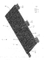
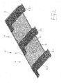
- the embodiment of in FIG. 1 shown solar system is indicated in its entirety by the reference numeral 1.
- the solar system 1 comprises a first solar system 2 and a second solar system 3.
- the solar system 2 comprises a solar module 4 and two raising means 5.1 and 5.2.
- the second solar system 3 comprises a solar module 6 and two raising means 5.2 and 5.3.
- the raising means 5.2 forms both a raising means of the solar system 2 and a raising means of the solar system.
- the solar system 2 will be described in more detail below, the statements on the characteristics of the solar system 2 for the solar system 3 apply mutatis mutandis.
- the solar module 4 is a typical, tabular solar module with a rectangular outer contour.
- the outer contour of the solar module 4 is formed by an aluminum profile frame 7, in which a photovoltaic element 25 is arranged.
- the two raising 5.1, 5.2 of the solar system 2 are designed identically.
- the Set-up 5.1 is available as a thermoformed, one-piece plastic molded part made of high density polyethylene (HDPE).
- the wall thickness of the set-up means 5.1 is about 3.7 mm and its density about 0.95 g / cm 3 .
- the total mass of the raising 5.1 is about 1.7 kg.
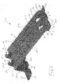
- the erection means 5.1 comprises a plate-shaped section 8, a first installation section 9, a second installation section 10, a first mounting section 11.1, 11.2 and a second mounting section 12.1, 12.2.
- the plate-shaped portion 8 extends from a first side edge 13 of the plate-shaped portion 8 to one of the first side edge 13 opposite, second side edge 14 of the plate-shaped portion 8.
- the plate-shaped portion 8 is in the form of a profiled panel or plate, wherein the profiling in Form of stiffening ribs 15.1, 15.2 is provided, which extend from the first side edge 13 to the second side edge 14 of the plate-shaped portion 8.
- the plate-shaped portion 8 comprises a support area 22, to which the solar module 4 (see FIG FIGS. 1 and 2 ) can be placed.
- the solar module 4 is over its entire length between its opposite side edges on the tops of the ribs 15.1, 15.2, whereby a deflection of the solar module 4 can be prevented in this area.
- the first installation section 9 and the second installation section 10 are formed as a development of the course of the plate-shaped section 8, wherein the course of the plate-shaped section 8 from the first side edge 13 in the first Aufstellabites 9 and from the second side edge 14 into the second Aufstellabrough 10 passes.
- the course of the stiffening ribs 15.1, 15.2 of the plate-shaped portion 8 is further developed in the first Aufstellabites 9 and the second Aufstellabites 10, so that the first Aufstellabrough 9 and the second Aufstellabrough 10 stiffening ribs 16.1, 16.2 or 17.1, 17.2 exhibit.
- the first and the second erecting sections 9, 10 each have sections 18, 19 on which the weighting means can be placed when the raising means 5.1 rests with the foot-side areas of the first and second erecting sections 9, 10 on a substrate.
- These sections 18, 19 each have an edge-side wall 20, 21 in order to make slippage of weighting means (not shown) from the sections 18, 19 more difficult.
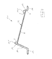
- the first and second Aufstellabites 9, 10 are formed such that the raising 5.1 is set up on the first and second Aufstellabites 9, 10 on a horizontal surface that the plate-shaped portion 8 in one of its first side edge 13 to its second side edge 14 ascending position can be set up on a horizontal surface.
- the first erecting section 9 is shorter than the second erecting section 10, so that the overall result is an oblique position of the plate-shaped section 8 on a horizontal surface.
- the first and second Aufstellabites 9, 10 on a horizontal surface of the support area 22 upwards, as directed away from the ground.
- Both the first mounting portion 11.1, 11.2 and the second mounting portion 12.1, 12.2 are each formed Imgliedrig.
- both the first support portion 11.1, 11.2 and the second support portion 12.1, 12.2 each consist of two in cross-section L-shaped elements, each forming a gap S, in which the solar module (see FIGS. 1 and 2 ) rests with a portion of its frame 7.
- the frame 7 of the solar module 4 is partially surrounded by the first support portion 11.1, 11.2 and the second support portion 12.1, 12.2, so that the solar module is mounted on the raising 5.1 and simultaneously rests on the support surface 22 of the plate-shaped portion 8.
- the solar module 4 is latched on the support surface 22 via the support sections 11.1, 11.2, 12.1, 12.2.
- the support sections 11.1, 11.2, 12.1, 12.2 are designed so flexible that that this easily bendable and thereby the solar module 4 can be snapped onto the support surface 22.
- the formed by the support sections 11.1, 11.2, 12.1, 12.2 gap S forms an undercut, behind which the solar module 4 rests at its latching with the encompassed by the support sections 11.1, 11.2, 12.1, 12.2 sections of its frame 7.
- openings 23, 24 are provided in the plate-shaped section 8, through which cables for connection to the photovoltaic element 25 of the solar module 4 can be guided.
- the raising means 5.1 and 5.2 of the solar system 2 are connected to one another exclusively via the solar module 4.
- Between the set-up 5.1, 5.2 remains a space that allows, for example, a simple maintenance and repair of the solar module 4.
- the solar module 4 is latched on an end-side region 4.1 and on an end-side region 4.2 opposite this region, respectively to an erection means 5.1 or 5.2 placed underground.
- the non-edge raising means in the embodiment so the raising 5.2, simultaneously serve for two adjacent solar systems 2, 3 as Aufstellstoff 5.2.
- the section 11.1 of the holding section 11.1, 11.2 and the section 12.1 of the holding section 12.1, 12.2 serves to hold the solar module 4 on the raising means 5.2 and the section 11.2 of the holding section 11.1, 11.2 and the section 12.2 of the holding section 12.1, 12.2 for holding the solar module 6 on Aufstellstoff 5.2.
Landscapes
- Engineering & Computer Science (AREA)
- Architecture (AREA)
- Civil Engineering (AREA)
- Structural Engineering (AREA)
- Physics & Mathematics (AREA)
- Life Sciences & Earth Sciences (AREA)
- Sustainable Development (AREA)
- Sustainable Energy (AREA)
- Thermal Sciences (AREA)
- Chemical & Material Sciences (AREA)
- Combustion & Propulsion (AREA)
- Mechanical Engineering (AREA)
- General Engineering & Computer Science (AREA)
- Photovoltaic Devices (AREA)
- Roof Covering Using Slabs Or Stiff Sheets (AREA)
Priority Applications (2)
| Application Number | Priority Date | Filing Date | Title |
|---|---|---|---|
| EP15170300.6A EP3101367A1 (fr) | 2015-06-02 | 2015-06-02 | Système solaire |
| PCT/EP2016/059018 WO2016192898A1 (fr) | 2015-06-02 | 2016-04-22 | Système photovoltaïque |
Applications Claiming Priority (1)
| Application Number | Priority Date | Filing Date | Title |
|---|---|---|---|
| EP15170300.6A EP3101367A1 (fr) | 2015-06-02 | 2015-06-02 | Système solaire |
Publications (1)
| Publication Number | Publication Date |
|---|---|
| EP3101367A1 true EP3101367A1 (fr) | 2016-12-07 |
Family
ID=53269410
Family Applications (1)
| Application Number | Title | Priority Date | Filing Date |
|---|---|---|---|
| EP15170300.6A Withdrawn EP3101367A1 (fr) | 2015-06-02 | 2015-06-02 | Système solaire |
Country Status (2)
| Country | Link |
|---|---|
| EP (1) | EP3101367A1 (fr) |
| WO (1) | WO2016192898A1 (fr) |
Cited By (1)
| Publication number | Priority date | Publication date | Assignee | Title |
|---|---|---|---|---|
| EP4545874A1 (fr) | 2023-10-23 | 2025-04-30 | Solardirekt Systems GmbH | Support pour la mise en place d'au moins un module solaire sur un sous-sol et procédé de disposition d'au moins un module solaire sur un tel support |
Families Citing this family (1)
| Publication number | Priority date | Publication date | Assignee | Title |
|---|---|---|---|---|
| DE102023133680A1 (de) * | 2023-12-01 | 2025-06-05 | Sunkon Gmbh | Anordnung zum Halten zumindest eines Photovoltaikmoduls oberhalb einer Fläche |
Citations (9)
| Publication number | Priority date | Publication date | Assignee | Title |
|---|---|---|---|---|
| DE4340402A1 (de) * | 1993-11-26 | 1995-06-01 | Siemens Solar Gmbh | Verfahren zur Kontaktierung von Dünnschichtsolarmodulen |
| EP2040014A2 (fr) * | 2007-09-24 | 2009-03-25 | Solarworld Aktiengesellschaft | Structure au sol / à toit plat empilable pour panneaux solaires |
| US20100212714A1 (en) * | 2009-02-20 | 2010-08-26 | Elie Rothschild | Modular solar racking system |
| DE102009019548A1 (de) * | 2009-04-30 | 2010-11-04 | Wilhelm Ötting Kunststoffverformung GmbH & Co. KG | Aufstellmodul und Aufstellsystem für Sonnenkollektoren |
| DE102009058794A1 (de) * | 2009-09-16 | 2011-03-17 | Jusung Engineering Co. Ltd., Gwangju-Si | Dünnschichttyp-Solarzelle und Verfahren zum Herstellen derselben, sowie Dünnschichttyp-Solarzellenmodul und Stromerzeugungssystem, welche die Dünnschichttyp-Solarzelle verwenden |
| DE202011102975U1 (de) * | 2011-07-07 | 2011-11-07 | Intelli Consult Gmbh | Kunststoff-Unterkonstruktion für (Dünnschicht-) Solarmodule auf Flachdächern |
| EP2418438A2 (fr) * | 2010-08-12 | 2012-02-15 | Centrosolar AG | Dispositif de support pour assembler un panneau solaire et système d'assemblage incorporant un tel dispositif |
| US20120125408A1 (en) * | 2010-07-30 | 2012-05-24 | Rene Reyes | Solar panel racking assembly and system |
| EP2538455A1 (fr) * | 2011-06-24 | 2012-12-26 | Hafenbahn GmbH & Co. KG | Petite centrale transportable pour la transformation de lumière solaire en énergie électrique et procédé d'établissement d'une telle petite centrale |
-
2015
- 2015-06-02 EP EP15170300.6A patent/EP3101367A1/fr not_active Withdrawn
-
2016
- 2016-04-22 WO PCT/EP2016/059018 patent/WO2016192898A1/fr not_active Ceased
Patent Citations (9)
| Publication number | Priority date | Publication date | Assignee | Title |
|---|---|---|---|---|
| DE4340402A1 (de) * | 1993-11-26 | 1995-06-01 | Siemens Solar Gmbh | Verfahren zur Kontaktierung von Dünnschichtsolarmodulen |
| EP2040014A2 (fr) * | 2007-09-24 | 2009-03-25 | Solarworld Aktiengesellschaft | Structure au sol / à toit plat empilable pour panneaux solaires |
| US20100212714A1 (en) * | 2009-02-20 | 2010-08-26 | Elie Rothschild | Modular solar racking system |
| DE102009019548A1 (de) * | 2009-04-30 | 2010-11-04 | Wilhelm Ötting Kunststoffverformung GmbH & Co. KG | Aufstellmodul und Aufstellsystem für Sonnenkollektoren |
| DE102009058794A1 (de) * | 2009-09-16 | 2011-03-17 | Jusung Engineering Co. Ltd., Gwangju-Si | Dünnschichttyp-Solarzelle und Verfahren zum Herstellen derselben, sowie Dünnschichttyp-Solarzellenmodul und Stromerzeugungssystem, welche die Dünnschichttyp-Solarzelle verwenden |
| US20120125408A1 (en) * | 2010-07-30 | 2012-05-24 | Rene Reyes | Solar panel racking assembly and system |
| EP2418438A2 (fr) * | 2010-08-12 | 2012-02-15 | Centrosolar AG | Dispositif de support pour assembler un panneau solaire et système d'assemblage incorporant un tel dispositif |
| EP2538455A1 (fr) * | 2011-06-24 | 2012-12-26 | Hafenbahn GmbH & Co. KG | Petite centrale transportable pour la transformation de lumière solaire en énergie électrique et procédé d'établissement d'une telle petite centrale |
| DE202011102975U1 (de) * | 2011-07-07 | 2011-11-07 | Intelli Consult Gmbh | Kunststoff-Unterkonstruktion für (Dünnschicht-) Solarmodule auf Flachdächern |
Cited By (1)
| Publication number | Priority date | Publication date | Assignee | Title |
|---|---|---|---|---|
| EP4545874A1 (fr) | 2023-10-23 | 2025-04-30 | Solardirekt Systems GmbH | Support pour la mise en place d'au moins un module solaire sur un sous-sol et procédé de disposition d'au moins un module solaire sur un tel support |
Also Published As
| Publication number | Publication date |
|---|---|
| WO2016192898A1 (fr) | 2016-12-08 |
Similar Documents
| Publication | Publication Date | Title |
|---|---|---|
| EP3683960B1 (fr) | Installation photovoltaïque | |
| DE202010006442U1 (de) | Gestell zur Befestigung von Solarmodulen | |
| EP2040014A2 (fr) | Structure au sol / à toit plat empilable pour panneaux solaires | |
| DE202011100205U1 (de) | Unterkonstruktion für Solaranlage sowie Solaranlage | |
| WO2013113307A2 (fr) | Corps flottant en forme de plaque et ensemble de corps flottants en forme de plaque | |
| AT521487A4 (de) | Vorrichtung zur vertikalen Anbringung an einer Wand | |
| EP3803228B1 (fr) | Système de montage pour monter des modules photovoltaïques sur des toits, comprenant des composants de système de montage reliés par des moyens d'assemblage par encliquetage | |
| EP2256821A2 (fr) | Installation photovoltaïque constituée de modules solaires à couche mince | |
| DE112014004754T5 (de) | Befestigungsstruktur eines Dünnschicht-Photovoltaikzellenmoduls | |
| DE102012108138B4 (de) | Trägerelement für ein Solarmodul, Trägersystem, Solaranlage und Verfahren zur Herstellung eines Trägerelements und/oder Trägersystems | |
| DE102015110908A1 (de) | Solarmodul | |
| DE202010001083U1 (de) | Vorrichtung zur Anordnung von Solarpaneelen und/oder Wärmekollektoren auf einem Untergrund | |
| EP3101367A1 (fr) | Système solaire | |
| EP2348264B1 (fr) | Plaque destinée à la création d'un dispositif d'agencement de panneaux solaires et/ou de collecteurs de chaleur sur un substrat, dispositif ainsi créé, utilisation d'une plaque, ainsi que procédé de création d'un dispositif pour l'agencement de panneaux solaires et/ou de collecteurs solaires sur un substrat | |
| WO2018138033A1 (fr) | Panneau solaire avec éléments de ferrure multifonctions et éléments de ferrure multifonctions | |
| EP2447620A1 (fr) | Dispositif d'agencement de panneaux solaires et/ou de collecteurs de chaleur sur une base ainsi que système comprenant au moins deux de ces dispositifs | |
| DE202012104361U1 (de) | Montagesystem für Solarmodule | |
| EP2522928B1 (fr) | Dispositif destiné au montage de constructions sur une surface plane ou une surface à faible inclinaison | |
| EP2554925B1 (fr) | Élément d'appui pour un module solaire | |
| DE102021119422A1 (de) | Anordnung mit Solarmodulen zur Abtrennung eines ersten Raumbereichs von einem zweiten Raumbereich | |
| DE102011122340A1 (de) | Photovoltaikanlage und ein Verfahren zur Herstellung einer Photovoltaikanlage | |
| DE202017102545U1 (de) | Treibfähiges Tragsystem für eine Anordnung von Sonnenkollektoren | |
| AT12834U1 (de) | Halterung für ein solarpaneel | |
| DE102022207465A1 (de) | Solarmodul und Verfahren zu dessen Montage | |
| DE202012002547U1 (de) | Vorrichtung zum Abstützen von Solarmodulen |
Legal Events
| Date | Code | Title | Description |
|---|---|---|---|
| PUAI | Public reference made under article 153(3) epc to a published international application that has entered the european phase |
Free format text: ORIGINAL CODE: 0009012 |
|
| STAA | Information on the status of an ep patent application or granted ep patent |
Free format text: STATUS: EXAMINATION IS IN PROGRESS |
|
| 17P | Request for examination filed |
Effective date: 20160121 |
|
| AK | Designated contracting states |
Kind code of ref document: A1 Designated state(s): AL AT BE BG CH CY CZ DE DK EE ES FI FR GB GR HR HU IE IS IT LI LT LU LV MC MK MT NL NO PL PT RO RS SE SI SK SM TR |
|
| AX | Request for extension of the european patent |
Extension state: BA ME |
|
| RBV | Designated contracting states (corrected) |
Designated state(s): AL AT BE BG CH CY CZ DE DK EE ES FI FR GB GR HR HU IE IS IT LI LT LU LV MC MK MT NL NO PL PT RO RS SE SI SK SM TR |
|
| STAA | Information on the status of an ep patent application or granted ep patent |
Free format text: STATUS: THE APPLICATION IS DEEMED TO BE WITHDRAWN |
|
| 18D | Application deemed to be withdrawn |
Effective date: 20171018 |