EP3101385A1 - Dispositif et procede de detection de topographies de surface - Google Patents
Dispositif et procede de detection de topographies de surface Download PDFInfo
- Publication number
- EP3101385A1 EP3101385A1 EP16163678.2A EP16163678A EP3101385A1 EP 3101385 A1 EP3101385 A1 EP 3101385A1 EP 16163678 A EP16163678 A EP 16163678A EP 3101385 A1 EP3101385 A1 EP 3101385A1
- Authority
- EP
- European Patent Office
- Prior art keywords
- sensor
- sample
- microscope
- reference sensor
- measured
- Prior art date
- Legal status (The legal status is an assumption and is not a legal conclusion. Google has not performed a legal analysis and makes no representation as to the accuracy of the status listed.)
- Granted
Links
Images

Classifications
-
- G—PHYSICS
- G02—OPTICS
- G02B—OPTICAL ELEMENTS, SYSTEMS OR APPARATUS
- G02B21/00—Microscopes
- G02B21/24—Base structure
- G02B21/241—Devices for focusing
- G02B21/245—Devices for focusing using auxiliary sources, detectors
-
- G—PHYSICS
- G01—MEASURING; TESTING
- G01B—MEASURING LENGTH, THICKNESS OR SIMILAR LINEAR DIMENSIONS; MEASURING ANGLES; MEASURING AREAS; MEASURING IRREGULARITIES OF SURFACES OR CONTOURS
- G01B11/00—Measuring arrangements characterised by the use of optical techniques
- G01B11/02—Measuring arrangements characterised by the use of optical techniques for measuring length, width or thickness
- G01B11/026—Measuring arrangements characterised by the use of optical techniques for measuring length, width or thickness by measuring distance between sensor and object
-
- G—PHYSICS
- G01—MEASURING; TESTING
- G01B—MEASURING LENGTH, THICKNESS OR SIMILAR LINEAR DIMENSIONS; MEASURING ANGLES; MEASURING AREAS; MEASURING IRREGULARITIES OF SURFACES OR CONTOURS
- G01B21/00—Measuring arrangements or details thereof, where the measuring technique is not covered by the other groups of this subclass, unspecified or not relevant
- G01B21/02—Measuring arrangements or details thereof, where the measuring technique is not covered by the other groups of this subclass, unspecified or not relevant for measuring length, width, or thickness
- G01B21/04—Measuring arrangements or details thereof, where the measuring technique is not covered by the other groups of this subclass, unspecified or not relevant for measuring length, width, or thickness by measuring coordinates of points
- G01B21/045—Correction of measurements
-
- G—PHYSICS
- G01—MEASURING; TESTING
- G01B—MEASURING LENGTH, THICKNESS OR SIMILAR LINEAR DIMENSIONS; MEASURING ANGLES; MEASURING AREAS; MEASURING IRREGULARITIES OF SURFACES OR CONTOURS
- G01B7/00—Measuring arrangements characterised by the use of electric or magnetic techniques
- G01B7/02—Measuring arrangements characterised by the use of electric or magnetic techniques for measuring length, width or thickness
- G01B7/023—Measuring arrangements characterised by the use of electric or magnetic techniques for measuring length, width or thickness for measuring distance between sensor and object
-
- G—PHYSICS
- G01—MEASURING; TESTING
- G01B—MEASURING LENGTH, THICKNESS OR SIMILAR LINEAR DIMENSIONS; MEASURING ANGLES; MEASURING AREAS; MEASURING IRREGULARITIES OF SURFACES OR CONTOURS
- G01B9/00—Measuring instruments characterised by the use of optical techniques
- G01B9/04—Measuring microscopes
-
- G—PHYSICS
- G02—OPTICS
- G02B—OPTICAL ELEMENTS, SYSTEMS OR APPARATUS
- G02B21/00—Microscopes
- G02B21/0004—Microscopes specially adapted for specific applications
- G02B21/002—Scanning microscopes
- G02B21/0024—Confocal scanning microscopes (CSOMs) or confocal "macroscopes"; Accessories which are not restricted to use with CSOMs, e.g. sample holders
- G02B21/0052—Optical details of the image generation
- G02B21/0064—Optical details of the image generation multi-spectral or wavelength-selective arrangements, e.g. wavelength fan-out, chromatic profiling
-
- G—PHYSICS
- G01—MEASURING; TESTING
- G01B—MEASURING LENGTH, THICKNESS OR SIMILAR LINEAR DIMENSIONS; MEASURING ANGLES; MEASURING AREAS; MEASURING IRREGULARITIES OF SURFACES OR CONTOURS
- G01B2210/00—Aspects not specifically covered by any group under G01B, e.g. of wheel alignment, caliper-like sensors
- G01B2210/50—Using chromatic effects to achieve wavelength-dependent depth resolution
Definitions
- the present invention in a first aspect relates to a device for detecting surface topographies according to the preamble of claim 1. In a further aspect, the invention relates to a method for detecting surface topographies according to the preamble of claim 15.
- a generic device has an optical microscope for microscopically detecting a topography of a surface of a sample in the direction of a height coordinate, wherein the topography of the surface is obtained in a temporal sequence of individual measurements. There is also a sample holder for holding the sample.
- a topography of the surface in the direction of a height coordinate is obtained from a surface of a sample in a temporal sequence of individual measurements with an optical microscope.
- confocal microscopy is used today as the standard method. For example, describe this process Rahlves, Seewig in “Optical Measurement of Technical Surfaces", Beuth Verlag GmbH, Berlin, 2009 ,
- the sample is scanned in all three spatial directions, that is to say point scanning systems in which an optical beam is guided in the xy direction over the sample.
- a movement of the sample relative to the detector unit ie in the z-direction, is required. From the intensity maximum as a function of the z position, the height information and thus the topography can be derived for each x / y location. It should be noted in these methods and devices that a comparatively long time is required to obtain a 3D topography using the raster scan.
- the device of the abovementioned type is developed according to the invention in that a reference sensor is provided for measuring changes in a height distance between the microscope and the sample holder and that a control and evaluation unit is provided for processing measurement data of the microscope and the reference sensor.
- the method of the type specified above is inventively further developed in that during the time sequence of individual measurements with a reference sensor Changes in a height distance between the microscope and a sample holder can be determined repeatedly.
- a core idea of the present invention can be regarded as avoiding a susceptibility of the microscopy methods to external influences of movement in that a repetitive reference measurement is performed temporally parallel to the actual measurement procedure, ie the determination of a surface topography by a plurality of individual measurements.
- the results of this reference measurement can be included in the actual measurement result, ie the surface topography, or can serve to keep the measuring device stable.
- the results of the reference measurement can also be utilized or incorporated by discarding measurement results of the determination of the surface topography, if the reference measurement provides a distance value which lies outside of an interval defined as permissible. Individual measurement results of the surface topography can therefore be discarded.
- the surface topography or surface topography data is understood to mean the assignment of a height, that is to say a z coordinate value, for all pairs of points x, y in a specific region of the sample.
- the present invention can be used to particular advantage in reflection microscopy in reflected light, for the characterization and measurement of surfaces and in particular for roughness measurements.
- the device according to the invention and the corresponding method make it possible to detect external influences such as vibrations, shocks and the like and to take them into account with regard to the measurement result.
- the entire measuring system therefore has a particular robustness against external influences.
- confocal wide-field systems based on structured illumination exist.
- a confocal sectional image is calculated from images taken with a structured illumination given, for example, by a grid.
- the wide field image can also be obtained.
- No pinhole arrangement is needed in the detection.
- An example of this is the ApoTome process marketed by Carl Zeiss, in which a lattice with different phase angles is imaged onto the samples. Since intensity modulations as a function of the phase position are present only for focal image components, an optical sectional image can be calculated therefrom.
- This method is also suitable for the measurement of technical surfaces.
- only two grating phases are used in the illumination, wherein the phases are detected sequentially in time by switching of light sources. This procedure is in DE 10 2007 018 048 A1 described.
- a stripe pattern is projected onto a sample surface at a triangulation angle, so that height information can be derived from the deformation of the pattern.
- different phase patterns are also generated here in order to completely grasp the surface.
- VivaTomes marketed by Carl Zeiss, which uses continuously changing structured illumination and calculates the optical cross-sectional image from two images taken in parallel, one containing extra-focal and focal and the other only extra-focal.
- An advantage of this method based on structured illumination is that parallel to the confocal image, a wide field image can also be obtained virtually in one shot. For the remaining problem that interfere with external movements, if for example in a z-position several shots to be made, the invention provides a remedy.
- the chromatic confocal principle has proven itself.
- a polychromatic light source is usually used, which illuminates the sample of interest via a chromatically acting refractive and / or diffractive element, whereby the z-information is spectrally encoded. If now the spectrum is measured behind a confocal pinhole in the detection, then the height information can be derived therefrom. It is also possible to use a tunable light source with sequential confocal detection, whereby a spectrum is likewise obtained. In most cases, the commercial sensors are point detectors, which always have the disadvantage of missing have xy parallelization.
- a chromatic multifocal arrangement with pinhole array is, for example, in DE 10 2007 019 267 A1 and DE 10 2012 009 836 A1 described.
- the focal points cover only part of the image field, so that a raster movement is still necessary and the problem of external influences exists.
- Systems based on a Nipkow disk have hitherto been implemented predominantly with color camera systems which only allow a limited height resolution and, in addition, have problems with color objects since superimposition of height and color information or spectral reflectivity occurs here.
- a multifocal chromatic arrangement was realized with the aid of a DMD.
- the chromatic height scan is performed with a tunable titanium sapphire laser.
- a design is realized that enables highly accurate 3D topography data without any mechanical movement elements.
- due to the tuning of the light source there is also a sequential image recording in accordance with the approaches based on a mechanical z-scan, so that here too the interfering influence is given by external vibrations or shocks which, as described herein, can be detected by the invention and is quantifiable.
- the measurement data of the reference sensor can be usefully used in different ways.
- an adjusting device for adjusting a height distance between the microscope and the sample holder is present and the control and evaluation cooperates with this adjustment and is set up to perform an active control of the height distance between the microscope and the reference point. It is therefore carried out based on measurement data of the reference sensor active control of the height difference. Particularly expedient is regulated to a constant height distance.
- the control and evaluation unit is advantageously set up for the subsequent correction of a measured topography of a surface of a sample with the aid of measured data of the reference sensor.
- the subsequent correction may be to discard or omit surface topography measurement points, if a reading of the reference sensor for the time the surface topography data in question was taken is not within an allowable defined interval. The surface topography data collected at this time of measurement or in an interval to be defined at this time of measurement are then ignored or, in other words, discarded.
- the optical microscope can basically be an optical microscope of a known type.
- the advantages of the invention are achieved in a particular way when the optical microscope and the microscopy methods used therewith require a finite time to detect the surface topography of a sample to be examined, in other words the probability that it will increase due to mechanical disturbances Falsifications of the measurement results.
- the microscope may have a scanner, in particular a point and / or line scanner.
- the optical microscope may be configured to perform one or more of the following microscopic methods: phase shift interferometry, optical coherence tomography, structured illumination, and / or phase retrieval microscopy.
- a resolution in the direction of the height coordinate can be achieved in optical microscopes, in particular by exploiting chromatic aberrations. Process variants in which the individual measurements are carried out with light of different wavelengths are therefore particularly preferred.
- very different sensors can be used for this purpose. Particularly accurate distance measurements are possible, for example, with capacitive sensors, with inductive sensors, eddy-current sensors and / or with magneto-inductive sensors.
- acceleration sensors can also be used. These may be particularly preferably attached to the sample holder, the example meadow can be a moving sample table basically known type. Relative movements between the microscope and the sample holder / table system can thus be recorded continuously.
- optical sensors for the reference sensors.
- This may in particular be a confocal sensor, a chromatic confocal sensor, an interferometric sensor, an autofocus sensor, a triangulation sensor, a stereoscopic distance sensor, a time of flight sensor, a phase shift optical sensors and / or a sensor with a Foucault cutting edge.
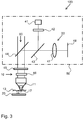
- the aforementioned autofocus sensor can also be based on the principle of dynamic focusing. Basically, a height information is converted into a 2D information, which succeeds, for example, with the aid of an astigmatic element in the detection beam path. Alternatively, for example, a Foucault cutting edge can also be used in the detection. Particularly interesting designs result from the use of special formations of the point distribution function, which in US-7,705,970 B2 and US-2011/0310266 A1 are described. US-7,705,970 B2 uses a rotational point distribution function in the form of a double helix, in which height information can be derived from the geometric alignment of the two helical cross sections relative to each other. This principle is related to FIG. 3 discussed in more detail.
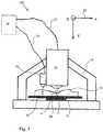
- FIG Fig. 1 Shown there is a device 100 according to the invention, which has as essential components an optical microscope 10 with a microscope objective 11 and an optical axis 14, a sample holder 20 and a reference sensor 30.
- the optical microscope 10 and the reference sensor 30 are connected via connecting lines 22, 24 to a control and evaluation device 18, which controls the microscope 10 and the reference sensor 30 and reads out measurement data in each case.
- the microscope 10, the reference sensor 30 and the sample holder 20 with a sample 12 arranged thereon are located in a housing 16.
- the sample holder 20 is a sample table of a basically known type.
- the reference sensor 30 is a optical sensor, for example, a triangulation sensor.
- the reference numeral 26 is in Fig. 1 a coordinate system shown.
- the z-axis is parallel to the optical axis 14 of the objective 11 of the optical microscope 10 and corresponds to the height direction, in which a topography of the surface 13 of the sample 12 is determined.
- This height direction z is also the direction in which the reference sensor 30 measures a distance or at least changes in distance to the reference point 32 on the sample.
- the reference sensor 30/31 may preferably collect measurement data during the entire measuring process of the microscope 10, so that any changes in distance due to disturbances can be detected.
- a structured element is initially present, which is arranged in a plane conjugate to the sample plane.
- the structured element represents a transmissive one- or two-dimensional lattice structure.
- This structure is formed by refractive and / or diffractive chromatic elements in imaged the sample space, so that here a chromatic splitting is generated, that is, the focus shifts depending on the wavelength in the z-direction.
- a polychromatic light source laser, halogen lamp, super luminescence diode
- a wavelength can be selected by a selective element in the first embodiment described.
- This selective element can be, for example, an AOTF, a prism, a grid or also a filter selection unit.
- the light can then be deflected by a deflection unit in a different direction.
- the deflection unit may, for example, be a fast-switching mirror (eg Galvo mirror), an AOD or a polarization rotation-based switching unit.
- a polarization filtering can be made.
- the deflection unit makes it possible to sequentially illuminate the grating from two sides using a collimating lens. If the lattice structure has a mirror finish, two lattice phases are accordingly imaged in the sample space.
- a beam splitter can be used for combining the transmission and reflection beam path.
- the light is then passed through a beam splitter to the sample, wherein the beam splitter is advantageously designed as a polarization beam splitter.
- a lambda / 4 plate can be arranged in the beam path, so that the light to be detected which goes to the sample and is reflected by the sample has a polarization rotated by 90 ° relative to one another and can be separated from one another as well.
- a polarization filter can furthermore be arranged in front of the detection camera.
- the wavelength can be tuned, which corresponds to a screening in the z direction. If the modulation contrast is evaluated as a function of the wavelength for each pixel, the corresponding height value of the sample is obtained. The modulation contrast is most pronounced at the wavelength whose z-focus position coincides with the sample surface.
- the structure which can also represent a 2D pinhole array (pinhole), moved to different positions and it will be taken with a camera corresponding images, but here only one light channel of the illumination is used.
- the camera can be used as a digital pinhole, so that a truly confocal image is obtained by calculating and composing the images taken at the individual positions (this corresponds, for example, to the Zeiss CSM 700).
- the height information can be derived by plotting the intensity over the wavelength.
- the structured element is completely eliminated and a sharpening function over the wavelength is determined in each case only for each local image area. This corresponds to the principle of focus variation. With sufficiently structured samples, this is sufficient to obtain height information.
- the structured element can also be an element for targeted introduction of a speckle pattern, which can be completely removed from the beam path.
- the reference sensor 30/31 may be read out parallel to each wavelength or z-shot of the microscope 10 become. If a distance change is detected, this can be taken into account passively directly in the measurement result. Another possibility is to actively respond to the distance change, for example, by changing the relative distance between the sample 12 and the microscope 10, for example by means of a movable table system as a sample holder 20.
- the Zeiss combines VivaTome with the chromatic confocal technology.
- a rotating disc is introduced with a mirrored structuring.
- the light reflected back from the sample is detected in two camera channels, which respectively correspond to a transmission or a reflection on the rotating disk.
- both a wide-field image and a confocal image can be calculated.
- the intensity information as a function of the wavelength yields the sought height information for each detection pixel.
- the wavelength is tuned, so that multiple individual recordings at a constant distance of the microscope to the sample are required. Reading out the reference sensor ensures that no artifacts occur.
- a movable pinhole array or a Nipkow disc is used.
- the pinhole array consists only of a pinhole.
- a detection of the entire sample surface is achieved by a movement (rotation, displacement) of the pinhole array.
- the spectral information or the height information coupled thereto can be obtained either with the aid of a tunable light source or with a broadband light source and spectral detection.
- the spectrometer can be realized with the aid of a line sensor. In any case, several individual measurements are required at least by the movement of the array, so that the reference measurement according to the invention makes sense here too.
- a non-movable pinhole array can be used, wherein the movement of the image of the same relative to the sample surface is realized by means of a scanning unit.
- a special feature of the reference beam path is that in the illumination, a phase element 42 is used, which is designed so that the focusing by means of the lens 11 generates a double helix-like point distribution function in the sample space.
- the lateral orientation of the double helix depends sensitively on the distance between the objective 11 and the sample surface 13 and, after back reflection, can be detected as an image on the sensor surface 48.
- the detector 48 can advantageously be designed as a quadrant diode.
- the present invention provides a novel apparatus and method that collects a total topography of a surface of a sample to be examined optically with methods known in the art at a nominally constant distance and fixed orientation between the optical sensor and the surface sample becomes.
- a reference signal is detected, which is sensitive to changes in distance between the sample body and the optical sensor, that is the optical microscope.
- the reference signal is actively or passively used to correct the topography measurement data.
Landscapes
- Physics & Mathematics (AREA)
- General Physics & Mathematics (AREA)
- Chemical & Material Sciences (AREA)
- Analytical Chemistry (AREA)
- Optics & Photonics (AREA)
- Spectroscopy & Molecular Physics (AREA)
- Microscoopes, Condenser (AREA)
- Length Measuring Devices By Optical Means (AREA)
Applications Claiming Priority (1)
| Application Number | Priority Date | Filing Date | Title |
|---|---|---|---|
| DE102015108912.2A DE102015108912A1 (de) | 2015-06-05 | 2015-06-05 | Vorrichtung und Verfahren zur Erfassung von Oberflächentopographien |
Publications (2)
| Publication Number | Publication Date |
|---|---|
| EP3101385A1 true EP3101385A1 (fr) | 2016-12-07 |
| EP3101385B1 EP3101385B1 (fr) | 2020-10-07 |
Family
ID=55650344
Family Applications (1)
| Application Number | Title | Priority Date | Filing Date |
|---|---|---|---|
| EP16163678.2A Not-in-force EP3101385B1 (fr) | 2015-06-05 | 2016-04-04 | Dispositif et procede de detection de topographies de surface |
Country Status (2)
| Country | Link |
|---|---|
| EP (1) | EP3101385B1 (fr) |
| DE (1) | DE102015108912A1 (fr) |
Cited By (7)
| Publication number | Priority date | Publication date | Assignee | Title |
|---|---|---|---|---|
| CN107621235A (zh) * | 2017-08-26 | 2018-01-23 | 东莞市三姆森光电科技有限公司 | 基于光谱共焦技术的手机曲面外壳轮廓测量方法及其测量设备 |
| CN109141325A (zh) * | 2018-09-14 | 2019-01-04 | 上海交通大学 | 金属表面涂镀层厚度的非接触式测量方法及装置 |
| EP3891545A1 (fr) * | 2018-12-07 | 2021-10-13 | Leica Microsystems CMS GmbH | Procédé de détermination de position automatique sur un ensemble d'échantillons et microscope correspondant |
| CN114002840A (zh) * | 2020-07-16 | 2022-02-01 | 卡尔蔡司显微镜有限责任公司 | 显微镜和用于确定到样品参考平面的距离的方法 |
| WO2024198067A1 (fr) * | 2023-03-28 | 2024-10-03 | 纳克微束(北京)有限公司 | Système et procédé d'inspection à mise au point automatique |
| CN119213524A (zh) * | 2022-09-07 | 2024-12-27 | 科磊股份有限公司 | 用于多柱显微镜的自动对焦传感器实施 |
| EP4632317A4 (fr) * | 2022-12-05 | 2026-02-11 | Shanghai Baiantek Sensing Tech Co Ltd | Dispositif de mesure de déplacement et son procédé de fabrication |
Families Citing this family (2)
| Publication number | Priority date | Publication date | Assignee | Title |
|---|---|---|---|---|
| GB2583369B (en) * | 2019-04-25 | 2021-09-15 | Andor Tech Limited | Microscope with focusing system |
| DE102019113975B4 (de) * | 2019-05-24 | 2023-10-19 | Abberior Instruments Gmbh | Verfahren und Vorrichtung zum Überwachen des Fokuszustands eines Mikroskops sowie Mikroskop |
Citations (8)
| Publication number | Priority date | Publication date | Assignee | Title |
|---|---|---|---|---|
| DE102006044235A1 (de) * | 2006-09-15 | 2008-03-27 | Leica Microsystems Cms Gmbh | Anordnung zum Bestimmen des Abstands, kapazitiver Abstandssensor und Verfahren zum automatischen Fokussieren eines Mikroskops |
| DE102007018048A1 (de) | 2007-04-13 | 2008-10-16 | Michael Schwertner | Verfahren und Anordnung zur optischen Abbildung mit Tiefendiskriminierung |
| DE102007019267A1 (de) | 2007-04-24 | 2008-10-30 | Degudent Gmbh | Messanordnung sowie Verfahren zum dreidimensionalen Messen eines Objekts |
| US7705970B2 (en) | 2006-06-05 | 2010-04-27 | The Regents Of The University Of Colorado | Method and system for optical imaging and ranging |
| US20110310266A1 (en) | 2010-06-22 | 2011-12-22 | Shingo Kato | Image pickup apparatus |
| US20130155413A1 (en) * | 2008-11-26 | 2013-06-20 | Zygo Corporation | Low coherence interferometry with scan error correction |
| DE102012009836A1 (de) | 2012-05-16 | 2013-11-21 | Carl Zeiss Microscopy Gmbh | Lichtmikroskop und Verfahren zur Bildaufnahme mit einem Lichtmikroskop |
| EP2789968A1 (fr) * | 2011-12-07 | 2014-10-15 | Konica Minolta, Inc. | Dispositif de mesure de forme |
-
2015
- 2015-06-05 DE DE102015108912.2A patent/DE102015108912A1/de not_active Withdrawn
-
2016
- 2016-04-04 EP EP16163678.2A patent/EP3101385B1/fr not_active Not-in-force
Patent Citations (8)
| Publication number | Priority date | Publication date | Assignee | Title |
|---|---|---|---|---|
| US7705970B2 (en) | 2006-06-05 | 2010-04-27 | The Regents Of The University Of Colorado | Method and system for optical imaging and ranging |
| DE102006044235A1 (de) * | 2006-09-15 | 2008-03-27 | Leica Microsystems Cms Gmbh | Anordnung zum Bestimmen des Abstands, kapazitiver Abstandssensor und Verfahren zum automatischen Fokussieren eines Mikroskops |
| DE102007018048A1 (de) | 2007-04-13 | 2008-10-16 | Michael Schwertner | Verfahren und Anordnung zur optischen Abbildung mit Tiefendiskriminierung |
| DE102007019267A1 (de) | 2007-04-24 | 2008-10-30 | Degudent Gmbh | Messanordnung sowie Verfahren zum dreidimensionalen Messen eines Objekts |
| US20130155413A1 (en) * | 2008-11-26 | 2013-06-20 | Zygo Corporation | Low coherence interferometry with scan error correction |
| US20110310266A1 (en) | 2010-06-22 | 2011-12-22 | Shingo Kato | Image pickup apparatus |
| EP2789968A1 (fr) * | 2011-12-07 | 2014-10-15 | Konica Minolta, Inc. | Dispositif de mesure de forme |
| DE102012009836A1 (de) | 2012-05-16 | 2013-11-21 | Carl Zeiss Microscopy Gmbh | Lichtmikroskop und Verfahren zur Bildaufnahme mit einem Lichtmikroskop |
Non-Patent Citations (1)
| Title |
|---|
| RAHLVES, SEEWIG: "Optisches Messen technischer Oberflächen", 2009, BEUTH VERLAG GMBH |
Cited By (10)
| Publication number | Priority date | Publication date | Assignee | Title |
|---|---|---|---|---|
| CN107621235A (zh) * | 2017-08-26 | 2018-01-23 | 东莞市三姆森光电科技有限公司 | 基于光谱共焦技术的手机曲面外壳轮廓测量方法及其测量设备 |
| CN107621235B (zh) * | 2017-08-26 | 2024-02-27 | 东莞市三姆森光电科技有限公司 | 基于光谱共焦技术的手机曲面外壳轮廓测量方法及其测量设备 |
| CN109141325A (zh) * | 2018-09-14 | 2019-01-04 | 上海交通大学 | 金属表面涂镀层厚度的非接触式测量方法及装置 |
| EP3891545A1 (fr) * | 2018-12-07 | 2021-10-13 | Leica Microsystems CMS GmbH | Procédé de détermination de position automatique sur un ensemble d'échantillons et microscope correspondant |
| US12298490B2 (en) | 2018-12-07 | 2025-05-13 | Leica Microsystems Cms Gmbh | Method for automatically determining the position in a sample arrangement and corresponding microscope |
| EP3891545B1 (fr) * | 2018-12-07 | 2026-01-28 | Leica Microsystems CMS GmbH | Procédé pour déterminer automatiquement la position sur un agencement d'échantillons et microscope correspondant |
| CN114002840A (zh) * | 2020-07-16 | 2022-02-01 | 卡尔蔡司显微镜有限责任公司 | 显微镜和用于确定到样品参考平面的距离的方法 |
| CN119213524A (zh) * | 2022-09-07 | 2024-12-27 | 科磊股份有限公司 | 用于多柱显微镜的自动对焦传感器实施 |
| EP4632317A4 (fr) * | 2022-12-05 | 2026-02-11 | Shanghai Baiantek Sensing Tech Co Ltd | Dispositif de mesure de déplacement et son procédé de fabrication |
| WO2024198067A1 (fr) * | 2023-03-28 | 2024-10-03 | 纳克微束(北京)有限公司 | Système et procédé d'inspection à mise au point automatique |
Also Published As
| Publication number | Publication date |
|---|---|
| EP3101385B1 (fr) | 2020-10-07 |
| DE102015108912A1 (de) | 2016-12-08 |
Similar Documents
| Publication | Publication Date | Title |
|---|---|---|
| EP3101385B1 (fr) | Dispositif et procede de detection de topographies de surface | |
| EP2673671B1 (fr) | Microscope équipé d'un dispositif de focalisation automatique et procédé de focalisation automatique pour microscopes | |
| EP2592462B1 (fr) | Procédé et agencement pour la mise au point automatique d'un microscope | |
| DE112005000639B4 (de) | Vorrichtung und Verfahren zur kombinierten interferometrischen und abbildungsbasierten Geometrieerfassung, insbesondere in der Mikrosystemtechnik | |
| DE102013016368B4 (de) | Lichtmikroskop und Mikroskopieverfahren zum Untersuchen einer mikroskopischen Probe | |
| EP1299691B1 (fr) | Procede de mesure sans contact de la geometrie d'objets | |
| WO2013171309A1 (fr) | Microscope optique et procédé de prise de vues au moyen d'un microscope optique | |
| WO2016193037A1 (fr) | Procédé pour la détermination d'une information de hauteur à résolution spatiale d'un échantillon au moyen d'un microscope à champ large et microscope à champ large | |
| DE102014108353A1 (de) | Verfahren und Vorrichtung zur Bestimmung von Geometrien an Messobjekten mittels eines kombinierten Sensorsystems | |
| WO2006032561A1 (fr) | Dispositif de mesure optique pour mesurer plusieurs surfaces d'un objet de mesure | |
| WO2018234419A1 (fr) | Procédé et système de microscopie servant à prendre une image | |
| WO2015044035A1 (fr) | Microscope optique confocal et procédé d'analyse d'un échantillon au moyen d'un microscope optique confocal | |
| WO2014023344A1 (fr) | Capteur chromatique amélioré et procédé | |
| EP3569976A1 (fr) | Tête de mesure de rugosité, dispositif avec ladite tête de mesure et utilisation correspondante | |
| DE112015002582T5 (de) | Einstellsystem für ein Phasenmodulationselement und Einstellverfahren für ein Phasenmodulationselement | |
| EP2601551A1 (fr) | Système autofocus | |
| EP3230684B1 (fr) | Microscope à balayage en profondeur et procédé pour faire fonctionner un microscope à balayage en profondeur | |
| DE102011115027A1 (de) | Kohärenzrasterinterferometer und Verfahren zur ortsaufgelösten optischen Vermessung der Oberflächengeometrie eines Objekts | |
| WO2020207795A1 (fr) | Microscope à feuille de lumière et procédé de détermination de l'indice de réfraction d'objets dans la chambre à échantillons | |
| EP2847542B1 (fr) | Dispositif doté d'une référence optique interne | |
| EP1805476B1 (fr) | Interferometre comprenant un systeme de miroirs pour effectuer des mesures sur un objet | |
| DE10251412A1 (de) | Anordnung zur Messung der Geometrie bzw. Struktur eines Objektes | |
| DE10321886A1 (de) | Robuster interferometrischer Sensor und Verfahren zur Objektabtastung | |
| DE102005005816A1 (de) | Vorrichtung zur Positionsbestimmung voneinander distanzierter Bereiche in transparenten und/oder diffusen Objekten | |
| DE102019111557B4 (de) | Sensor und Verfahren zur Bestimmung von geometrischen Eigenschaften eines Messobjekts |
Legal Events
| Date | Code | Title | Description |
|---|---|---|---|
| PUAI | Public reference made under article 153(3) epc to a published international application that has entered the european phase |
Free format text: ORIGINAL CODE: 0009012 |
|
| STAA | Information on the status of an ep patent application or granted ep patent |
Free format text: STATUS: THE APPLICATION HAS BEEN PUBLISHED |
|
| AK | Designated contracting states |
Kind code of ref document: A1 Designated state(s): AL AT BE BG CH CY CZ DE DK EE ES FI FR GB GR HR HU IE IS IT LI LT LU LV MC MK MT NL NO PL PT RO RS SE SI SK SM TR |
|
| AX | Request for extension of the european patent |
Extension state: BA ME |
|
| STAA | Information on the status of an ep patent application or granted ep patent |
Free format text: STATUS: REQUEST FOR EXAMINATION WAS MADE |
|
| 17P | Request for examination filed |
Effective date: 20170307 |
|
| RBV | Designated contracting states (corrected) |
Designated state(s): AL AT BE BG CH CY CZ DE DK EE ES FI FR GB GR HR HU IE IS IT LI LT LU LV MC MK MT NL NO PL PT RO RS SE SI SK SM TR |
|
| STAA | Information on the status of an ep patent application or granted ep patent |
Free format text: STATUS: EXAMINATION IS IN PROGRESS |
|
| 17Q | First examination report despatched |
Effective date: 20180308 |
|
| GRAP | Despatch of communication of intention to grant a patent |
Free format text: ORIGINAL CODE: EPIDOSNIGR1 |
|
| STAA | Information on the status of an ep patent application or granted ep patent |
Free format text: STATUS: GRANT OF PATENT IS INTENDED |
|
| RIC1 | Information provided on ipc code assigned before grant |
Ipc: G01B 7/02 20060101ALI20200408BHEP Ipc: G01B 9/04 20060101ALI20200408BHEP Ipc: G01B 11/02 20060101ALI20200408BHEP Ipc: G01B 21/04 20060101AFI20200408BHEP Ipc: G02B 21/24 20060101ALI20200408BHEP Ipc: G02B 21/00 20060101ALI20200408BHEP |
|
| INTG | Intention to grant announced |
Effective date: 20200507 |
|
| GRAS | Grant fee paid |
Free format text: ORIGINAL CODE: EPIDOSNIGR3 |
|
| GRAA | (expected) grant |
Free format text: ORIGINAL CODE: 0009210 |
|
| STAA | Information on the status of an ep patent application or granted ep patent |
Free format text: STATUS: THE PATENT HAS BEEN GRANTED |
|
| AK | Designated contracting states |
Kind code of ref document: B1 Designated state(s): AL AT BE BG CH CY CZ DE DK EE ES FI FR GB GR HR HU IE IS IT LI LT LU LV MC MK MT NL NO PL PT RO RS SE SI SK SM TR |
|
| REG | Reference to a national code |
Ref country code: GB Ref legal event code: FG4D Free format text: NOT ENGLISH |
|
| REG | Reference to a national code |
Ref country code: CH Ref legal event code: EP Ref country code: AT Ref legal event code: REF Ref document number: 1321627 Country of ref document: AT Kind code of ref document: T Effective date: 20201015 |
|
| REG | Reference to a national code |
Ref country code: DE Ref legal event code: R096 Ref document number: 502016011362 Country of ref document: DE |
|
| REG | Reference to a national code |
Ref country code: IE Ref legal event code: FG4D Free format text: LANGUAGE OF EP DOCUMENT: GERMAN |
|
| REG | Reference to a national code |
Ref country code: NL Ref legal event code: MP Effective date: 20201007 |
|
| PG25 | Lapsed in a contracting state [announced via postgrant information from national office to epo] |
Ref country code: GR Free format text: LAPSE BECAUSE OF FAILURE TO SUBMIT A TRANSLATION OF THE DESCRIPTION OR TO PAY THE FEE WITHIN THE PRESCRIBED TIME-LIMIT Effective date: 20210108 Ref country code: NO Free format text: LAPSE BECAUSE OF FAILURE TO SUBMIT A TRANSLATION OF THE DESCRIPTION OR TO PAY THE FEE WITHIN THE PRESCRIBED TIME-LIMIT Effective date: 20210107 Ref country code: NL Free format text: LAPSE BECAUSE OF FAILURE TO SUBMIT A TRANSLATION OF THE DESCRIPTION OR TO PAY THE FEE WITHIN THE PRESCRIBED TIME-LIMIT Effective date: 20201007 Ref country code: RS Free format text: LAPSE BECAUSE OF FAILURE TO SUBMIT A TRANSLATION OF THE DESCRIPTION OR TO PAY THE FEE WITHIN THE PRESCRIBED TIME-LIMIT Effective date: 20201007 Ref country code: PT Free format text: LAPSE BECAUSE OF FAILURE TO SUBMIT A TRANSLATION OF THE DESCRIPTION OR TO PAY THE FEE WITHIN THE PRESCRIBED TIME-LIMIT Effective date: 20210208 Ref country code: FI Free format text: LAPSE BECAUSE OF FAILURE TO SUBMIT A TRANSLATION OF THE DESCRIPTION OR TO PAY THE FEE WITHIN THE PRESCRIBED TIME-LIMIT Effective date: 20201007 |
|
| REG | Reference to a national code |
Ref country code: LT Ref legal event code: MG4D |
|
| PG25 | Lapsed in a contracting state [announced via postgrant information from national office to epo] |
Ref country code: ES Free format text: LAPSE BECAUSE OF FAILURE TO SUBMIT A TRANSLATION OF THE DESCRIPTION OR TO PAY THE FEE WITHIN THE PRESCRIBED TIME-LIMIT Effective date: 20201007 Ref country code: SE Free format text: LAPSE BECAUSE OF FAILURE TO SUBMIT A TRANSLATION OF THE DESCRIPTION OR TO PAY THE FEE WITHIN THE PRESCRIBED TIME-LIMIT Effective date: 20201007 Ref country code: IS Free format text: LAPSE BECAUSE OF FAILURE TO SUBMIT A TRANSLATION OF THE DESCRIPTION OR TO PAY THE FEE WITHIN THE PRESCRIBED TIME-LIMIT Effective date: 20210207 Ref country code: LV Free format text: LAPSE BECAUSE OF FAILURE TO SUBMIT A TRANSLATION OF THE DESCRIPTION OR TO PAY THE FEE WITHIN THE PRESCRIBED TIME-LIMIT Effective date: 20201007 Ref country code: PL Free format text: LAPSE BECAUSE OF FAILURE TO SUBMIT A TRANSLATION OF THE DESCRIPTION OR TO PAY THE FEE WITHIN THE PRESCRIBED TIME-LIMIT Effective date: 20201007 Ref country code: BG Free format text: LAPSE BECAUSE OF FAILURE TO SUBMIT A TRANSLATION OF THE DESCRIPTION OR TO PAY THE FEE WITHIN THE PRESCRIBED TIME-LIMIT Effective date: 20210107 |
|
| PG25 | Lapsed in a contracting state [announced via postgrant information from national office to epo] |
Ref country code: HR Free format text: LAPSE BECAUSE OF FAILURE TO SUBMIT A TRANSLATION OF THE DESCRIPTION OR TO PAY THE FEE WITHIN THE PRESCRIBED TIME-LIMIT Effective date: 20201007 |
|
| REG | Reference to a national code |
Ref country code: DE Ref legal event code: R097 Ref document number: 502016011362 Country of ref document: DE |
|
| PG25 | Lapsed in a contracting state [announced via postgrant information from national office to epo] |
Ref country code: SM Free format text: LAPSE BECAUSE OF FAILURE TO SUBMIT A TRANSLATION OF THE DESCRIPTION OR TO PAY THE FEE WITHIN THE PRESCRIBED TIME-LIMIT Effective date: 20201007 Ref country code: LT Free format text: LAPSE BECAUSE OF FAILURE TO SUBMIT A TRANSLATION OF THE DESCRIPTION OR TO PAY THE FEE WITHIN THE PRESCRIBED TIME-LIMIT Effective date: 20201007 Ref country code: CZ Free format text: LAPSE BECAUSE OF FAILURE TO SUBMIT A TRANSLATION OF THE DESCRIPTION OR TO PAY THE FEE WITHIN THE PRESCRIBED TIME-LIMIT Effective date: 20201007 Ref country code: EE Free format text: LAPSE BECAUSE OF FAILURE TO SUBMIT A TRANSLATION OF THE DESCRIPTION OR TO PAY THE FEE WITHIN THE PRESCRIBED TIME-LIMIT Effective date: 20201007 Ref country code: RO Free format text: LAPSE BECAUSE OF FAILURE TO SUBMIT A TRANSLATION OF THE DESCRIPTION OR TO PAY THE FEE WITHIN THE PRESCRIBED TIME-LIMIT Effective date: 20201007 Ref country code: SK Free format text: LAPSE BECAUSE OF FAILURE TO SUBMIT A TRANSLATION OF THE DESCRIPTION OR TO PAY THE FEE WITHIN THE PRESCRIBED TIME-LIMIT Effective date: 20201007 |
|
| PLBE | No opposition filed within time limit |
Free format text: ORIGINAL CODE: 0009261 |
|
| STAA | Information on the status of an ep patent application or granted ep patent |
Free format text: STATUS: NO OPPOSITION FILED WITHIN TIME LIMIT |
|
| PG25 | Lapsed in a contracting state [announced via postgrant information from national office to epo] |
Ref country code: DK Free format text: LAPSE BECAUSE OF FAILURE TO SUBMIT A TRANSLATION OF THE DESCRIPTION OR TO PAY THE FEE WITHIN THE PRESCRIBED TIME-LIMIT Effective date: 20201007 |
|
| 26N | No opposition filed |
Effective date: 20210708 |
|
| PG25 | Lapsed in a contracting state [announced via postgrant information from national office to epo] |
Ref country code: AL Free format text: LAPSE BECAUSE OF FAILURE TO SUBMIT A TRANSLATION OF THE DESCRIPTION OR TO PAY THE FEE WITHIN THE PRESCRIBED TIME-LIMIT Effective date: 20201007 Ref country code: IT Free format text: LAPSE BECAUSE OF FAILURE TO SUBMIT A TRANSLATION OF THE DESCRIPTION OR TO PAY THE FEE WITHIN THE PRESCRIBED TIME-LIMIT Effective date: 20201007 |
|
| PG25 | Lapsed in a contracting state [announced via postgrant information from national office to epo] |
Ref country code: MC Free format text: LAPSE BECAUSE OF FAILURE TO SUBMIT A TRANSLATION OF THE DESCRIPTION OR TO PAY THE FEE WITHIN THE PRESCRIBED TIME-LIMIT Effective date: 20201007 Ref country code: SI Free format text: LAPSE BECAUSE OF FAILURE TO SUBMIT A TRANSLATION OF THE DESCRIPTION OR TO PAY THE FEE WITHIN THE PRESCRIBED TIME-LIMIT Effective date: 20201007 |
|
| GBPC | Gb: european patent ceased through non-payment of renewal fee |
Effective date: 20210404 |
|
| PG25 | Lapsed in a contracting state [announced via postgrant information from national office to epo] |
Ref country code: LU Free format text: LAPSE BECAUSE OF NON-PAYMENT OF DUE FEES Effective date: 20210404 |
|
| REG | Reference to a national code |
Ref country code: BE Ref legal event code: MM Effective date: 20210430 |
|
| PG25 | Lapsed in a contracting state [announced via postgrant information from national office to epo] |
Ref country code: LI Free format text: LAPSE BECAUSE OF NON-PAYMENT OF DUE FEES Effective date: 20210430 Ref country code: CH Free format text: LAPSE BECAUSE OF NON-PAYMENT OF DUE FEES Effective date: 20210430 Ref country code: GB Free format text: LAPSE BECAUSE OF NON-PAYMENT OF DUE FEES Effective date: 20210404 Ref country code: FR Free format text: LAPSE BECAUSE OF NON-PAYMENT OF DUE FEES Effective date: 20210430 |
|
| PG25 | Lapsed in a contracting state [announced via postgrant information from national office to epo] |
Ref country code: IE Free format text: LAPSE BECAUSE OF NON-PAYMENT OF DUE FEES Effective date: 20210404 |
|
| PG25 | Lapsed in a contracting state [announced via postgrant information from national office to epo] |
Ref country code: IS Free format text: LAPSE BECAUSE OF FAILURE TO SUBMIT A TRANSLATION OF THE DESCRIPTION OR TO PAY THE FEE WITHIN THE PRESCRIBED TIME-LIMIT Effective date: 20210207 |
|
| REG | Reference to a national code |
Ref country code: AT Ref legal event code: MM01 Ref document number: 1321627 Country of ref document: AT Kind code of ref document: T Effective date: 20210404 |
|
| PG25 | Lapsed in a contracting state [announced via postgrant information from national office to epo] |
Ref country code: BE Free format text: LAPSE BECAUSE OF NON-PAYMENT OF DUE FEES Effective date: 20210430 |
|
| PGFP | Annual fee paid to national office [announced via postgrant information from national office to epo] |
Ref country code: DE Payment date: 20220420 Year of fee payment: 7 |
|
| PG25 | Lapsed in a contracting state [announced via postgrant information from national office to epo] |
Ref country code: AT Free format text: LAPSE BECAUSE OF NON-PAYMENT OF DUE FEES Effective date: 20210404 |
|
| PG25 | Lapsed in a contracting state [announced via postgrant information from national office to epo] |
Ref country code: HU Free format text: LAPSE BECAUSE OF FAILURE TO SUBMIT A TRANSLATION OF THE DESCRIPTION OR TO PAY THE FEE WITHIN THE PRESCRIBED TIME-LIMIT; INVALID AB INITIO Effective date: 20160404 |
|
| PG25 | Lapsed in a contracting state [announced via postgrant information from national office to epo] |
Ref country code: CY Free format text: LAPSE BECAUSE OF FAILURE TO SUBMIT A TRANSLATION OF THE DESCRIPTION OR TO PAY THE FEE WITHIN THE PRESCRIBED TIME-LIMIT Effective date: 20201007 |
|
| REG | Reference to a national code |
Ref country code: DE Ref legal event code: R119 Ref document number: 502016011362 Country of ref document: DE |
|
| PG25 | Lapsed in a contracting state [announced via postgrant information from national office to epo] |
Ref country code: DE Free format text: LAPSE BECAUSE OF NON-PAYMENT OF DUE FEES Effective date: 20231103 |
|
| PG25 | Lapsed in a contracting state [announced via postgrant information from national office to epo] |
Ref country code: MK Free format text: LAPSE BECAUSE OF FAILURE TO SUBMIT A TRANSLATION OF THE DESCRIPTION OR TO PAY THE FEE WITHIN THE PRESCRIBED TIME-LIMIT Effective date: 20201007 |
|
| PG25 | Lapsed in a contracting state [announced via postgrant information from national office to epo] |
Ref country code: MT Free format text: LAPSE BECAUSE OF FAILURE TO SUBMIT A TRANSLATION OF THE DESCRIPTION OR TO PAY THE FEE WITHIN THE PRESCRIBED TIME-LIMIT Effective date: 20201007 |
|
| PG25 | Lapsed in a contracting state [announced via postgrant information from national office to epo] |
Ref country code: TR Free format text: LAPSE BECAUSE OF FAILURE TO SUBMIT A TRANSLATION OF THE DESCRIPTION OR TO PAY THE FEE WITHIN THE PRESCRIBED TIME-LIMIT Effective date: 20201007 |