EP3101480B1 - Bilderzeugungsvorrichtung und steuerungsverfahren dafür - Google Patents
Bilderzeugungsvorrichtung und steuerungsverfahren dafür Download PDFInfo
- Publication number
- EP3101480B1 EP3101480B1 EP15199209.6A EP15199209A EP3101480B1 EP 3101480 B1 EP3101480 B1 EP 3101480B1 EP 15199209 A EP15199209 A EP 15199209A EP 3101480 B1 EP3101480 B1 EP 3101480B1
- Authority
- EP
- European Patent Office
- Prior art keywords
- printing medium
- transporting guide
- image forming
- forming apparatus
- guide
- Prior art date
- Legal status (The legal status is an assumption and is not a legal conclusion. Google has not performed a legal analysis and makes no representation as to the accuracy of the status listed.)
- Active
Links
Images




Classifications
-
- G—PHYSICS
- G03—PHOTOGRAPHY; CINEMATOGRAPHY; ANALOGOUS TECHNIQUES USING WAVES OTHER THAN OPTICAL WAVES; ELECTROGRAPHY; HOLOGRAPHY
- G03G—ELECTROGRAPHY; ELECTROPHOTOGRAPHY; MAGNETOGRAPHY
- G03G15/00—Apparatus for electrographic processes using a charge pattern
- G03G15/20—Apparatus for electrographic processes using a charge pattern for fixing, e.g. by using heat
- G03G15/2003—Apparatus for electrographic processes using a charge pattern for fixing, e.g. by using heat using heat
- G03G15/2014—Apparatus for electrographic processes using a charge pattern for fixing, e.g. by using heat using heat using contact heat
- G03G15/2017—Structural details of the fixing unit in general, e.g. cooling means, heat shielding means
- G03G15/2028—Structural details of the fixing unit in general, e.g. cooling means, heat shielding means with means for handling the copy material in the fixing nip, e.g. introduction guides, stripping means
-
- G—PHYSICS
- G03—PHOTOGRAPHY; CINEMATOGRAPHY; ANALOGOUS TECHNIQUES USING WAVES OTHER THAN OPTICAL WAVES; ELECTROGRAPHY; HOLOGRAPHY
- G03G—ELECTROGRAPHY; ELECTROPHOTOGRAPHY; MAGNETOGRAPHY
- G03G15/00—Apparatus for electrographic processes using a charge pattern
- G03G15/65—Apparatus which relate to the handling of copy material
- G03G15/6555—Handling of sheet copy material taking place in a specific part of the copy material feeding path
- G03G15/657—Feeding path after the transfer point and up to the fixing point, e.g. guides and feeding means for handling copy material carrying an unfused toner image
-
- G—PHYSICS
- G03—PHOTOGRAPHY; CINEMATOGRAPHY; ANALOGOUS TECHNIQUES USING WAVES OTHER THAN OPTICAL WAVES; ELECTROGRAPHY; HOLOGRAPHY
- G03G—ELECTROGRAPHY; ELECTROPHOTOGRAPHY; MAGNETOGRAPHY
- G03G2215/00—Apparatus for electrophotographic processes
- G03G2215/00362—Apparatus for electrophotographic processes relating to the copy medium handling
- G03G2215/00535—Stable handling of copy medium
- G03G2215/00675—Mechanical copy medium guiding means, e.g. mechanical switch
Definitions
- Embodiments of the present disclosure relate to an image forming apparatus having a transporting guide that guides a printing medium between a transferring apparatus and a fusing unit, and a control method thereof.
- an image forming apparatus is an apparatus configured that forms images on a printing medium, and includes a printer, a photocopying apparatus, a facsimile, and a multi-function apparatus combined and implemented the functions of the printer, the photocopying apparatus, and the facsimile.
- the image forming apparatus as such includes a plurality of developing apparatuses to develop an electrostatic latent image into a visible image by use of a developer, a light scanning apparatus that forms an electrostatic latent image on a surface of a photoreceptor by radiating light at the photoreceptor of the developing apparatus, a transferring apparatus to transfer the visible image developed at the photoreceptor to printing medium, and a fusing unit that fuses the photoreceptor on the printing medium.
- a transporting guide configured to guide the printing medium having the photoreceptor transferred thereto by use of the transferring apparatus to the fusing unit is disposed between the transferring apparatus and the fusing unit.
- the transporting guide that performs a role to guide a front end of the printing medium transferred from the transferring apparatus to the fusing unit may be entered between a heating roller and a pressing roller of the fusing unit.
- US 2005/0207802 A1 , EP 353243 A2 and US 2009/0067909 each discloses an image forming apparatus having transfer medium guide means; US 2010/0061741 A1 discloses an image forming apparatus having an angle changing unit; US 2012/313318 A1 discloses an image forming apparatus having a guide unit that can switch between positions based on a sheet transporting direction of an ejecting transport member.
- an image forming apparatus capable of reducing static electricity generated from friction between a printing medium transported toward a transferring roller and a transporting guide guiding the printing medium.
- an image forming apparatus includes inter alia a plurality of fusing rollers that fuse a developer at a printing medium, and a transporting guide configured to guide the printing medium being transported toward the fusing rollers.
- the transporting guide is movably installed to move in between a first position to guide at least a part of the printing medium and a second position spaced apart by a certain distance from the first position, wherein in the second position, contact between the transporting guide and the printing medium is reduced.
- a driving device to move the transporting guide may be included.
- the driving device includes a driving motor, a cam rotated by the driving motor and configured to move the transporting guide in a first direction, and an elastic member to elastically support the transporting guide in a second direction opposite the first direction.
- the driving device includes a driving axis rotated by use of the driving motor, the cam is provided as a pair of cams, each of the pair of cams installed at a respective side of the driving axis, and the transporting guide may include a pair of supporting portions, each of the pair of supporting portions provided at a respective side of the transporting guide as to correspond to the each of the pair of cams.
- the driving device includes a driving motor, a pinion rotated by use of the driving motor, and a rack teeth-coupled to the pinion while disposed at the transporting guide.
- the driving device includes a driving axis rotated by use of the driving motor, the pinion is provided as a pair of pinions, each of the pair of pinions respectively installed at a side of the driving axis, and the rack is provided as a pair of racks, each of the racks of the pair of racks respectively disposed at a side of the transporting guide as to correspond to the respective each of the pair of pinions.
- the transporting guide is positioned at the first position before the front end of the printing medium has entered in between the pair of fusing rollers, and is moved from the first position to the second position when the front end of the printing medium has entered in between the pair of the fusing rollers.
- the apparatus includes a static removing member that removes static electricity of the printing medium being transported toward the fusing rollers is .
- the static removing member moves along with the transporting guide.
- the static removing member is positioned at the first position before the front end of the printing medium has entered in between the pair of fusing rollers, and is moved from the first position to the second position when the front end of the printing medium has entered in between the pair of the fusing rollers.
- an image forming apparatus includes a body, a developing unit to develop an electrostatic latent image to a visible image, a transferring apparatus to transfer the visible image of the developing unit to a printing medium, a fusing unit to fuse the visible image transferred to the printing medium, and a static removing member to remove static electricity of the printing medium being transported from the transferring apparatus to the fusing unit, and the static removing member is movably installed at an inside of the body so as to move in between a first position and a second position spaced apart by a predetermined distance from the first position depending on a position of the printing medium, wherein in the second position, contact between the static removing member and the printing medium is reduced.
- an image forming apparatus includes inter alia a body, a developing unit that develops an electrostatic latent image to a visible image, a transferring apparatus that transfers the visible image of the developing unit to a printing medium, a fusing unit that fuses the visible image transferred to the printing medium, a transporting guide movably installed at an inside the body that guides the printing medium from the transferring apparatus to the fusing unit, and a driving device that moves the transporting guide.
- a control method of an image forming apparatus includes inter alia confirming a position of a front end of a printing medium being transported toward a position in between a plurality of fusing rollers, maintaining of a state of a transporting guide positioned at a first position, upon confirming that the front end of the printing medium has not entered in between the plurality of fusing rollers, and moving the transporting guide from the first position to a second position spaced apart from the first position toward one side of a first direction, upon confirming that the front end of the printing medium is entered in between the fusing rollers, wherein in the second position, contact between the transporting guide and the printing medium is reduced.
- the transporting guide upon confirming that the position of a rear end of the printing medium has not passed through the transferring roller, the transporting guide maintains a state of being positioned at the second position, and upon confirming that the position of the rear end of the printing medium has passed through the transferring roller, the transporting guide is moved from the second position to the first position.
- An image forming apparatus in accordance with at least one exemplary embodiment, including a transporting guide positioned at a first position when guiding a front end of a printing medium, and moved to a second position spaced apart from the first position after the front end of the printing medium has entered in between fusing rollers, reduces friction and reduces subsequent static electricity between the printing medium and the transporting guide.
- An image forming apparatus in accordance with an embodiment of at least one exemplary embodiment includes a static removing member that removes static electricity formed at a printing medium movably installed thereto, and contact between the static removing member and the printing medium can be reduced
- an image forming apparatus in accordance with at least one exemplary embodiment includes a body 10 forming an exterior appearance of the image forming apparatus, a printing medium supplying unit 20 provided, for example, at a lower portion of the body 10 and at which printing mediums P to be used at the image forming apparatus in accordance may be stored, a plurality of developing units 30C, 30M, 30Y, and 30K to develop an electrostatic latent image to a visible image by use of different colors through a developer, a light scanning unit 40 that forms an electrostatic latent image at photoreceptors 31C, 31M, 31Y, and 30K of the charged developing units 30C, 30M, 30Y, and 30K by radiating light, developing units 30C, 30M, 30Y, and 30K that radiates the visible image formed at the photoreceptors 31C, 31M, 31Y, and 31K at the printing medium P (see, for example, FIG. 4 ) delivered from the printing medium supplying unit 20, and a fusing unit 60
- the body 10 may be provided with a loading unit 10a at an upper portion thereof.
- a side of the loading unit 10a may be provided with a paper discharging unit 10b through which a printing medium P, for example having completed with a formation of an image, may be discharged.
- An opening 10c may be provided at a side, e.g., one side of the body 10 so, for example, repairing or changing components or replacing consumable items at an inside of the body 10 may be performed.
- a cover 11 may be installed at the a side, e.g., one side of the body 10 to open/close the opening 10c.
- a lower end of the cover 11 may be rotatably installed at the body 10 to open/close the opening 10c while rotating with respect to the lower end as a center.
- the printing medium supplying unit 20 includes a printing medium cartridge 21 that may be formed in the shape of a drawer and may be movably installed at the body 10.
- a knock-up plate 22 may be disposed at an inside of the printing medium cartridge 21 and at which the printing medium P may be loaded.
- the printing medium supplying unit 20 at least one exemplary embodiment is vertically provided in two units.
- the developing units 30C, 30M, 30Y, and 30K may each include the photoreceptors 31C, 31M, 31Y, and 31K at which an electrostatic latent image is formed by use of the light scanning unit 40.
- the developing units 30C, 30M, 30Y, and 30K may each include a developing roller to supply a developer, and a charging roller to charge the photoreceptors 31C, 31M, 31Y, and 31K.
- the developing units 30C, 30M, 30Y, and 30K include four units of developing units 30C, 30M, 30Y, and 30K each provided with the certain one developer having one of the colors such as Cyan C, Magenta M, Yellow Y, and Black K stored at an inside thereof, and the developing units 30C, 30M, 30Y, and 30K each may develop the one of the colors of Cyan C, Magenta M, Yellow Y, and Black K.
- the four units of developing units 30C, 30M, 30Y, and 30K may be evenly disposed at lower sides of the developing units 30C, 30M, 30Y, and 30K.
- the light scanning unit 40 may form an electrostatic latent image on the surface of the each of the photoreceptors 31C, 31M, 31Y, and 31K by radiating the light provided with image information at the photoreceptors 31C, 31M, 31Y, and 31K provided at the developing units 30C, 30M, 30Y, and 30K, respectively.
- the developing units 30C, 30M, 30Y, and 30K may include a middle transferring belt 51 at which the each developer is developed while overlapped as visible images at the photoreceptors 31C, 31M, 31Y, and 31K, and a driving roller 52 and a passive roller 53 disposed at inside of the middle transferring belt 51 as to rotate the middle transferring belt 51.
- a transferring apparatus 50 includes transferring rollers 54 and 55 to transfer the developer.
- the transferring rollers 54 and 55 includes first transferring rollers 54 each disposed to respectively face each of the photoreceptors 31C, 31M, 31Y, and 31K of the developing units 30C, 30M, 30Y, and 30K in a state that the middle transferring belt 51 is interpositioned therein between as to transfer the visible images of the photoreceptors 31C, 31M, 31Y, and 31K are transferred to the middle transferring belt 51.
- a second transferring roller 55 may be disposed to face the passive roller 53 in a state that the middle transferring belt 51 is interpositioned, for example, in between the second transferring roller 55 and the passive roller 53 as to have the visible images of the middle transferring belt 51 transferred to the printing medium P.
- the second transferring roller 55 may be installed at an inner side of the cover 11.
- the cover 11 includes a supporting frame 15 (see, for example, FIG. 3 ) provided at an inner side of the cover 11 that supports the second transferring roller 55 and a transporting guide 70,.
- the fusing unit 60 includes a plurality of fusing rollers, e.g., a pair of fusing rollers 61 and 62 to apply heat and pressure at the printing medium P having transferred with the developer.
- the fusing rollers 61 and 62 include a heating roller 61 to generate heat, and a pressing roller 62 provided with an outer circumferential surface thereof formed with elastically deformable material and to press the printing medium P at the outer circumferential surface of the heating roller 61, for example.
- a lower portion of the body 10 includes a pick-up roller 12 disposed at an upper portion of one side of the printing medium supplying unit 20 to pick up the printing mediums P loaded at an inside of the printing medium supplying unit 20, for example, one-by-one, and a transporting roller 13 that guides the printing medium P picked up by the pick-up roller 12 to the transferring apparatus 50.
- An upper portion of the body 10 may include a pair of rollers 14, to discharge the printing medium P passed through the fusing unit 60 through the paper discharging unit 10b, disposed at an inner side of the paper discharging unit 10b.
- An inside of the body 10 may include the transporting guide 70 disposed in between the second transferring roller 55 and the fusing rollers 61 and 62.
- the transporting guide 70 may guide the printing medium P, e.g., the front end of the printing medium toward a position between the fusing rollers 61 and 62 while the printing medium P is provided with the developer transferred thereto while passing through the second transferring roller 55.
- the transporting guide 70 may be movably installed at an inside of the body 10.
- the inside of the body 10 may be provided with a sensor (not illustrated) that detects a position of the printing medium, e.g., a front end and a rear end of the printing medium P.
- a driving device 80 may generate a driving force that moves the transporting guide 70, such that the transporting guide 70 may be moved by driving the driving device 80 according to the position of the printing medium P detected through the sensor.
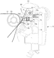
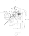
- the transporting guide 70 may move between a first position (see, for example, FIG. 4 ) that guides the front end of the printing medium P and a second position (see, for example, FIG. 5 ) spaced apart by a certain distance from the first position to reduce contact with respect to the printing medium P. That is, the transporting guide 70 may guide the front end of the printing medium P at the first position. According to an embodiment, in a case when there is no need to guide the front end of the printing medium P, e.g., as the front end of the printing medium P is entered in between the fusing rollers 61 and 62, the transporting guide 70 may move to the second position, e.g., to reduce the friction between the transporting guide 70 and the printing medium P.
- the transporting guide 70 includes a guide member 71 that guides the printing medium P while making contact with the printing medium P being transported toward the fusing unit 60, and a moving member 72 movably installed at an inside of the body 10.
- the guide member 71 may be coupled to an upper side of the moving member 72, and move along the moving member 72.
- the guide member 71 may be extended in a vertical direction, and include a plurality of guide ribs 71a distantly and parallelly disposed with respect to each other in a horizontal direction, and may guide the printing medium P toward an upper side.
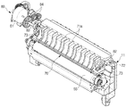
- the moving member 72 includes a coupling portion 72a provided with the guide unit 71 coupled to an upper side thereof, a pair of guide units 72b provided at sides of the coupling portion 72a and movably installed at an inside of the body 10 to guide the moving member 72, and a pair of supporting portions 72c supported at a cam surface of a cam 82 of the driving device 80.
- the two guide units 72b are each provided with a guide hole 72d horizontally extended in a moving direction of the transporting guide 70.
- the supporting frame 15 includes a fusing unit 15a at which the transporting guide is movably fused, and a guide protrusion 15b protruded toward an upper side from the fusing unit 15a and penetrating through the guide hole 72d.
- the two guide protrusion 15b may each be provided with a guide bush 73 installed thereto by use of a coupling member S such as a screw, and the moving member 72 may maintain a state of being movably installed through the guide bush 73 at the supporting frame 15.
- the supporting portion 72c may be formed from one side of the guide unit 72b toward the surface extended in a perpendicular direction, and reciprocally interact with respect to the cam 82.
- the driving device 80 includes a driving motor 81 that generates a rotational force, the pair of cams 82 their rotate by receiving the rotational force from the driving motor 81, a driving axis 83 provided with the two cams 82 installed at sides thereof, and a plurality of gears 84 that may be disposed between the driving motor 81 and the driving axis 83, e.g., to decelerate the speed.
- the driving device 80 includes a plurality of, e.g., a pair of elastic members 74 configured such that the transporting guide 70 moved by use of the cam 82 may be returned to an original position while supporting the transporting guide 70.
- the two cams 82 may each include a cam surface gradually changed while the radius of the outer circumferential surface thereof proceeds toward a radial direction.
- the cam surfaces of the two cams 82 may each be supported at one surface of the each of the supporting portions 72c, and the two elastic members 74 may be installed at the supporting frame 15 as to support the opposite surfaces of the supporting portions 72c.
- the transporting guide 70 may be moved toward a second direction, which is an opposite direction to the first direction, as the elastic members 74 are elastically restored, and as illustrated on FIG. 5 , the transporting guide 70 is moved again to the first position.
- the first position of the transporting guide 70 is referred to as a position to transport the front end of the printing medium P toward a position in between the two fusing rollers 61 and 62, and the second position of the transporting guide 70 may be referred to as a position to reduce the friction in between the transporting guide 70 and the printing medium P.
- a lower side of the transporting guide 70 may be provided with a static removing member 90 configured to remove static electricity
- the static removing member 90 may move toward the first position and the second position along with the transporting guide 70.
- the static removing member 90 may be formed in the shape of a rectangular plate.
- a static removing portion 91 having the shape of a saw tooth may be provided at one side end of the static removing member 90 while the static removing portion 91 may be provided to face one side surface of the printing medium P being delivered from the transferring apparatus 50 to the fusing unit 60.
- the charged photoreceptors 31C, 31M, 31Y, and 31K may be provided with an electrostatic latent image formed thereto by the light radiated from the light scanning unit 40.
- the charged photoreceptors 31C, 31M, 31Y, and 31K having formed with the electrostatic latent image is supplied with the developers by use of the developing roller. Therefore, the electrostatic latent images are developed into a visible image by use of the developers.
- the visible images developed at the photoreceptors 31C, 31M, 31Y, and 31K by use of the developers may be overlappingly transferred to the transferring belt 51, and the visible image formed by being overlappingly transferred is transferred to the printing medium P by use of the second transferring roller 55.
- the printing medium P at which the developers are transferred while passing in between the second transferring roller 55 and the transferring belt 51 may be delivered by use of the transporting guide 70 to the position in between of the heating roller 61 and the pressing roller 62 of the fusing unit 60.
- the developers transferred to the printing medium P may be fused at the printing medium P by use of the heat and pressure applied by use of the heating roller 61 and the pressing roller 62 of the fusing unit 60.
- the printing medium After passing through the second transferring roller 55, at least a part of the printing medium, e.g., the front end of the printing medium P is guided to the position in between of the heating roller 61 and the pressing roller 62 by use of the transporting guide 70 positioned at the first position.
- a confirmation may be made if the front end of the printing medium P is entered into the position in between of the two fusing rollers 61 and 62 of the fusing unit 60.
- the transporting guide 70 Prior to the front end of the printing medium P entering into the position in between of the two fusing rollers 61 and 62, the transporting guide 70, as illustrated on FIG. 4 , may be maintained in a state of being positioned at the first position.
- power may be authorized at the driving motor 81 and a rotational force may be generated at the driving motor 81, and the rotational force generated at the driving motor 81 may be delivered to the cams 82 through the driving axis 83 so that the cams 82 may be rotated, for example, by about 180° in a single direction.
- the portion having a relatively larger radius on the outer circumferential surface of the cam 82 following the rotation of the cam 82 may be supported at one surface of the supporting portion 72c, and accordingly, the moving member 72 and the guide member 71 installed at the moving member 72 may be moved from the first position to the second position, as illustrated on FIG. 5 , while the elastic member 74 is deformed.
- the transporting guide 70 may maintain a state of being positioned at the second position, for example, until the rear end of the printing medium P is passed through the second transferring roller 55 of the transferring apparatus 50.
- power may be again authorized at the driving motor 81 and a rotational force is generated.
- the rotational force generated at the driving motor 81 may be delivered to the cams 82 through the driving axis 83 so that the cams 82 are rotated again by about 180° in a single direction.
- the portion having a relatively smaller radius on the outer circumferential surface of the cam 82 following the rotation of the cam 82 may be supported at one surface of the supporting portion 72c, and accordingly, as the force applied to the supporting portion 72c is released, the moving member 72 and the guide member 71 installed at the moving member 72 may be moved from the second position to the first position, as illustrated on FIG. 4 , by the use of the elastic restoring force of the elastic member 74.
- the static removing member 90 installed at the transporting guide 70 may also be moved along with the transporting guide 70. That is, the static removing member 90 may be positioned at the first position until the front end of the printing medium P has entered in between the fusing rollers 61 and 62, and when the front end of the printing medium P has entered in between the fusing rollers 61 and 62, the static removing member 90 may be moved to the second position. After the rear end of the printing medium P is passed through the second transferring roller 55, the static removing member 90 may be moved from the second position to the first position again.
- the static removing portion 91 of the static removing member 90 may be prevented from making contact with one side surface of the printing medium P, and accordingly, a decrease in the quality of image that may be generated in a case when the static removing portion 91 makes contact with the printing medium P may be reduced.
- the driving device 80 configured to move the transporting guide 70 includes the cams 82 and the elastic member 74, but is not limited hereto
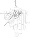
- a transporting guide 70' may include a pair of pinions 85 having a driving axis 83 provided with the driving device 80 installed at an each side thereof, and a pair of racks 72e disposed at each of the both sides of the moving member 72 as to correspond with the pair of pinions 85 and configured to respectively teeth-coupled to the two pinions 85.
- the image forming apparatus having the driving device 80 as such is provided such that the transporting guide 70' may be moved, as illustrated in FIG. 8 , from a first position to a second position, for example, by a rotational force through the racks 72e as the driving axis 83 and the pinions 85 coupled to the driving axis 83 are rotated, for example, in a single direction by use of the driving motor 81 in a state that the transporting guide 70' is positioned at the first position, and the transporting guide 70 is returned, as illustrated on FIG. 7 , from the second position to the first position by being delivered with rotational force through the racks 72e as the driving axis 83 and the pinions 85 are rotated in a reverse direction by use of the driving motor 81.
- the driving device 80 includes a transporting guide 70 that may be moved through the driving motor.
- the cams 82 and the elastic member 74, and the driving device 80 according to at least one exemplary embodiment are provided such that the transporting guide 70 may be moved through the driving motor 81, limited hereto, and the image forming apparatus may be delivered with driving force from another structure of the image forming apparatus, such as a driving device configured to drive a structure, for example, a developing unit, a transferring unit, or a fusing unit, so that the transporting guide may be moved.
- the transferring apparatus in the present embodiment includes the middle transferring belt, the first transferring roller, and the second transferring roller, but is not limited hereto, and the movable transporting guide of at least one exemplary embodiment may be applied as it is to an image forming apparatus having a single transferring roller provided with the transferring apparatus installed while facing a photoreceptor without the structures corresponding to the middle transferring belt and the first transferring roller.
Landscapes
- Physics & Mathematics (AREA)
- General Physics & Mathematics (AREA)
- Feeding Of Articles By Means Other Than Belts Or Rollers (AREA)
- Engineering & Computer Science (AREA)
- Plasma & Fusion (AREA)
- Electrostatic Charge, Transfer And Separation In Electrography (AREA)
Claims (13)
- Bilderzeugungsvorrichtung, die Folgendes umfasst:eine Übertragungsvorrichtung (50), um ein sichtbares Bild auf ein Druckmedium zu übertragen, mehrere Fixierwalzen (61, 62), die einen Entwickler an dem Druckmedium fixieren; undeine Transportführung (70), die dazu konfiguriert ist, das Druckmedium, das transportiert wird, zu den mehreren Fixierwalzen (61, 62) hin zu führen, wobei die Transportführung (70) zwischen der Übertragungsvorrichtung (50) und den mehreren Fixierwalzen (61, 62) angeordnet und beweglich installiert ist, um sich zwischen einer ersten Position, um wenigstens einen Teil des Druckmediums zu führen, und einer zweiten Position zu bewegen, die um einen zuvor bestimmten Abstand von der ersten Position beabstandet ist, dadurch gekennzeichnet, dass in der zweiten Position eine Berührung zwischen der Transportführung (70) und dem Druckmedium verringert ist.
- Bilderzeugungsvorrichtung nach Anspruch 1, die ferner Folgendes umfasst:
eine Antriebsvorrichtung (80), die dazu konfiguriert ist, die Transportführung (70) zu bewegen. - Bilderzeugungsvorrichtung nach Anspruch 2, wobei:
die Antriebsvorrichtung (80) Folgendes umfasst:einen Antriebsmotor (81),einen Nocken (82), der durch den Antriebsmotor (81) gedreht und dazu konfiguriert ist, die Transportführung (70) in eine erste Richtung zu bewegen, undein elastisches Element (74), um die Transportführung (70) in einer der ersten Richtung entgegengesetzten zweiten Richtung elastisch zu stützen. - Bilderzeugungsvorrichtung nach Anspruch 3, wobei:die Antriebsvorrichtung (80) ferner eine Antriebsachse (83) umfasst, die durch den Antriebsmotor (81) gedreht wird,der Nocken (82) als ein Nockenpaar (82) bereitgestellt ist, und jeder des Nockenpaares (82) an einer jeweiligen Seite der Antriebsachse (83) installiert ist, unddie Transportführung (70) ein Paar von stützenden Abschnitten (72c) umfasst, wobei jeder des Paares von stützenden Abschnitten (72c) an einer jeweiligen Seite der Transportführung (70) bereitgestellt ist, um jedem des Nockenpaares (82) zu entsprechen.
- Bilderzeugungsvorrichtung nach Anspruch 1, wobei:
die Antriebsvorrichtung (80) Folgendes umfasst:einen Antriebsmotor (81),ein Ritzel (85), das durch den Antriebsmotor (81) gedreht wird, undeine Zahnstange (72e), die mit dem Ritzel (85) zahngekoppelt ist, während sie an der Transportführung (70) angeordnet ist. - Bilderzeugungsvorrichtung nach Anspruch 5, wobei:die Antriebsvorrichtung (80) ferner eine Antriebsachse (83) umfasst, die durch den Antriebsmotor (81) gedreht wird,das Ritzel (85) in einem Ritzelpaar (85) bereitgestellt ist, und jedes des Ritzelpaares (85) an einer jeweiligen Seite der Antriebsachse (83) installiert ist, unddie Zahnstange (72e) als ein Zahnstangenpaar (72e) bereitgestellt ist, und jede des Zahnstangenpaares (72e) an einer jeweiligen Seite der Transportführung (70) angeordnet ist, um jedem des Ritzelpaares (72e) zu entsprechen.
- Bilderzeugungsvorrichtung nach Anspruch 1, wobei:
die Transportführung (70) an der ersten Position positioniert ist, bevor das vordere Ende des Druckmediums zwischen die mehreren Fixierwalzen (61, 62) eingeführt wurde, und dazu konfiguriert ist, von der ersten Position zu der zweiten Position bewegt zu werden, wenn das vordere Ende des Druckmediums zwischen die mehreren Fixierwalzen (61, 62) eingeführt wird. - Bilderzeugungsvorrichtung nach Anspruch 1, die ferner Folgendes umfasst:ein statisches Entfernungselement (90), um eine statische Elektrizität des Druckmediums, das zu den Fixierwalzen (61, 62) hin transportiert wird, zu entfernen, undwobei das statische Entfernungselement (90) dazu konfiguriert ist, sich zusammen mit der Transportführung (70) zu bewegen, während es an der Transportführung (70) installiert ist.
- Bilderzeugungsvorrichtung nach Anspruch 8, wobei:
das statische Entfernungselement (90) an der ersten Position positioniert ist, bevor das vordere Ende des Druckmediums zwischen das Fixierwalzenpaar (61, 62) eingeführt wird, und dazu konfiguriert ist, von der ersten Position zu der zweiten Position bewegt zu werden, wenn das vordere Ende des Druckmediums zwischen dem Fixierwalzenpaar (61, 62) eingeführt wird. - Bilderzeugungsvorrichtung, die Folgendes umfasst:einen Körper (10),eine Entwicklungseinheit (30C, 30M, 30Y, 30K), um ein elektrostatisch latentes Bild zu einem sichtbaren Bild zu entwickeln,eine Übertragungsvorrichtung (50), um das sichtbare Bild der Entwicklungseinheit (30C, 30M, 30Y, 30K) auf ein Druckmedium zu übertragen,eine Fixiereinheit (60), um das sichtbare Bild, das auf das Druckmedium übertragen wird, zu fixieren, undein statisches Entfernungselement (90), um die statische Elektrizität des Druckmediums, das von der Übertragungsvorrichtung (50) zu der Fixiereinheit (60) transportiert wird, zu entfernen,wobei das statische Entfernungselement (90) an einer Innenseite des Körpers (10) beweglich installiert ist, um sich zwischen einer ersten Position und einer zweiten Position zu bewegen, die in Abhängigkeit von einer Position des Druckmediums um einen zuvor bestimmten Abstand von der ersten Position beabstandet ist, dadurch gekennzeichnet, dass in der zweiten Position die Berührung zwischen dem statischen Entfernungselement (90) und dem Druckmedium verringert ist.
- Bilderzeugungsvorrichtung nach Anspruch 10, wobei:
das statische Entfernungselement (90) an der ersten Position positioniert ist, bevor das vordere Ende des Druckmediums in die Fixiereinheit (60) eingeführt wird, und dazu konfiguriert ist, um von der ersten Position zu der zweiten Position bewegt zu werden, wenn das vordere Ende des Druckmediums in die Fixiereinheit (60) eingeführt wird. - Steuerverfahren einer Bilderzeugungsvorrichtung, die Folgendes umfasst:Bestätigen einer Position eines vorderen Endes eines Druckmediums, das von einer Übertragungsvorrichtung zu einer Position zwischen mehreren Fixierwalzen (61, 62) hin transportiert wird, undAufrechterhalten eines Zustands einer Transportführung (70), die zwischen der Übertragungsvorrichtung und den mehreren Fixierwalzen, die an einer ersten Position positioniert sind, angeordnet ist, nachdem bestätigt wird, dass ein vorderes Ende des Druckmediums nicht zwischen die mehreren Fixierwalzen (61, 62) eingeführt wurde, undBewegen der Transportführung (70) von der ersten Position zu einer zweiten Position, die von der ersten Position beabstandet ist, zu einer Seite einer ersten Richtung hin, nachdem bestätigt wird, dass das vordere Ende des Druckmediums zwischen die Fixierwalzen (61, 62) eingeführt wurde, dadurch gekennzeichnet, dass in der zweiten Position die Berührung zwischen der Transportführung (70) und dem Druckmedium verringert ist.
- Steuerverfahren der Bilderzeugungsvorrichtung nach Anspruch 12, wobei:
nachdem bestätigt wird, dass eine Position eines hinteren Endes des Druckmediums nicht durch eine Übertragungswalze (55) geführt wurde, die Transportführung (70) einen Zustand aufrechterhält, in der zweiten Position positioniert zu sein, und nachdem bestätigt wird, dass die Position des hinteren Endes des Druckmediums durch die Übertragungswalze (55) geführt wurde, die Transportführung (70) sich von der zweiten Position zu der ersten Position bewegt.
Applications Claiming Priority (1)
| Application Number | Priority Date | Filing Date | Title |
|---|---|---|---|
| KR1020150079798A KR20160143292A (ko) | 2015-06-05 | 2015-06-05 | 화상형성장치 및 그 제어방법 |
Publications (2)
| Publication Number | Publication Date |
|---|---|
| EP3101480A1 EP3101480A1 (de) | 2016-12-07 |
| EP3101480B1 true EP3101480B1 (de) | 2021-05-19 |
Family
ID=54979378
Family Applications (1)
| Application Number | Title | Priority Date | Filing Date |
|---|---|---|---|
| EP15199209.6A Active EP3101480B1 (de) | 2015-06-05 | 2015-12-10 | Bilderzeugungsvorrichtung und steuerungsverfahren dafür |
Country Status (3)
| Country | Link |
|---|---|
| US (1) | US9897951B2 (de) |
| EP (1) | EP3101480B1 (de) |
| KR (1) | KR20160143292A (de) |
Families Citing this family (1)
| Publication number | Priority date | Publication date | Assignee | Title |
|---|---|---|---|---|
| JP7151242B2 (ja) * | 2018-07-24 | 2022-10-12 | 富士フイルムビジネスイノベーション株式会社 | 案内構造、定着装置、画像形成装置 |
Citations (1)
| Publication number | Priority date | Publication date | Assignee | Title |
|---|---|---|---|---|
| US20120313318A1 (en) * | 2011-06-07 | 2012-12-13 | Oki Data Corporation | Image forming apparatus |
Family Cites Families (15)
| Publication number | Priority date | Publication date | Assignee | Title |
|---|---|---|---|---|
| JP3432650B2 (ja) * | 1995-09-09 | 2003-08-04 | 株式会社リコー | 画像形成装置 |
| US6661989B2 (en) | 2002-04-09 | 2003-12-09 | Xerox Corporation | Xerographic fusing apparatus with input sheet guide |
| JP4112518B2 (ja) | 2004-03-22 | 2008-07-02 | シャープ株式会社 | 画像形成装置 |
| JP2007127677A (ja) * | 2005-10-31 | 2007-05-24 | Ricoh Co Ltd | ガイド部材および画像形成装置 |
| KR101395115B1 (ko) | 2007-09-06 | 2014-05-16 | 삼성전자주식회사 | 화상형성기기 |
| JP2009128481A (ja) * | 2007-11-21 | 2009-06-11 | Ricoh Co Ltd | 転写装置及び画像形成装置 |
| US20090148212A1 (en) * | 2007-12-10 | 2009-06-11 | Kabushiki Kaisha Toshiba | Fixing device |
| JP4646008B2 (ja) * | 2008-06-30 | 2011-03-09 | 株式会社沖データ | 媒体搬送装置及び画像形成装置 |
| JP5445917B2 (ja) | 2008-09-08 | 2014-03-19 | 株式会社リコー | 画像形成装置 |
| JP2010281894A (ja) * | 2009-06-02 | 2010-12-16 | Ricoh Co Ltd | 画像形成装置、画像形成装置の画像形成方法、およびプログラム |
| JP5326958B2 (ja) * | 2009-09-15 | 2013-10-30 | 株式会社リコー | 定着装置及び画像形成装置 |
| US8805218B2 (en) * | 2010-02-17 | 2014-08-12 | Kabushiki Kaisha Toshiba | Image forming apparatus, toner image transfer and fixing method, and computer-readable recording medium having recorded thereon toner image transfer and fixing program |
| US8855544B2 (en) * | 2011-03-08 | 2014-10-07 | Sharp Kabushiki Kaisha | Image forming apparatus with charge eliminating guide member |
| JP5835646B2 (ja) * | 2011-06-30 | 2015-12-24 | 株式会社リコー | ガイド装置、定着装置及び画像形成装置 |
| JP6012410B2 (ja) | 2012-11-05 | 2016-10-25 | キヤノン株式会社 | 画像形成装置 |
-
2015
- 2015-06-05 KR KR1020150079798A patent/KR20160143292A/ko not_active Withdrawn
- 2015-12-07 US US14/960,762 patent/US9897951B2/en active Active
- 2015-12-10 EP EP15199209.6A patent/EP3101480B1/de active Active
Patent Citations (1)
| Publication number | Priority date | Publication date | Assignee | Title |
|---|---|---|---|---|
| US20120313318A1 (en) * | 2011-06-07 | 2012-12-13 | Oki Data Corporation | Image forming apparatus |
Also Published As
| Publication number | Publication date |
|---|---|
| KR20160143292A (ko) | 2016-12-14 |
| US9897951B2 (en) | 2018-02-20 |
| EP3101480A1 (de) | 2016-12-07 |
| US20160357133A1 (en) | 2016-12-08 |
Similar Documents
| Publication | Publication Date | Title |
|---|---|---|
| US9182736B2 (en) | Image forming apparatus | |
| US10345751B2 (en) | Image forming apparatus | |
| US20140294420A1 (en) | Image forming apparatus | |
| US12487559B2 (en) | Image forming apparatus having improved mountability of a cartridge while conserving space | |
| EP2199873B1 (de) | Entwicklungseinheit für eine Bilderzeugungsvorrichtung | |
| JP6833362B2 (ja) | 画像形成装置 | |
| EP2450751B1 (de) | Bilderzeugungsvorrichtung | |
| US9229424B2 (en) | Image forming apparatus | |
| EP3101480B1 (de) | Bilderzeugungsvorrichtung und steuerungsverfahren dafür | |
| US20170255158A1 (en) | Image forming apparatus | |
| JP2017090564A (ja) | 画像形成装置および画像形成システム | |
| US20130236226A1 (en) | Image forming apparatus with compact sheet conveyance path | |
| WO2020146052A1 (en) | Imaging system | |
| EP3121657B1 (de) | Bilderzeugungsvorrichtung | |
| EP2784597B1 (de) | Bilderzeugungsvorrichtung | |
| KR20120035520A (ko) | 화상형성장치 | |
| US8971759B2 (en) | Image forming apparatus | |
| JP5222877B2 (ja) | 軸部材保持機構、感光体ドラムユニット及び画像形成装置 | |
| JP2008024396A (ja) | 手差しトレイ及び画像形成装置 | |
| EP2657778B1 (de) | Bilderzeugungsvorrichtung mit einer Reinigungseinheit zum Reinigen einer optischen Sensoreinheit | |
| JP6260027B2 (ja) | 画像形成装置 | |
| JP5505882B2 (ja) | 用紙供給装置、及び画像形成装置 |
Legal Events
| Date | Code | Title | Description |
|---|---|---|---|
| PUAI | Public reference made under article 153(3) epc to a published international application that has entered the european phase |
Free format text: ORIGINAL CODE: 0009012 |
|
| STAA | Information on the status of an ep patent application or granted ep patent |
Free format text: STATUS: THE APPLICATION HAS BEEN PUBLISHED |
|
| AK | Designated contracting states |
Kind code of ref document: A1 Designated state(s): AL AT BE BG CH CY CZ DE DK EE ES FI FR GB GR HR HU IE IS IT LI LT LU LV MC MK MT NL NO PL PT RO RS SE SI SK SM TR |
|
| AX | Request for extension of the european patent |
Extension state: BA ME |
|
| RIN1 | Information on inventor provided before grant (corrected) |
Inventor name: JU, JEONG YONG |
|
| STAA | Information on the status of an ep patent application or granted ep patent |
Free format text: STATUS: REQUEST FOR EXAMINATION WAS MADE |
|
| RAP1 | Party data changed (applicant data changed or rights of an application transferred) |
Owner name: S-PRINTING SOLUTION CO., LTD. |
|
| 17P | Request for examination filed |
Effective date: 20170216 |
|
| RBV | Designated contracting states (corrected) |
Designated state(s): AL AT BE BG CH CY CZ DE DK EE ES FI FR GB GR HR HU IE IS IT LI LT LU LV MC MK MT NL NO PL PT RO RS SE SI SK SM TR |
|
| RAP1 | Party data changed (applicant data changed or rights of an application transferred) |
Owner name: HP PRINTING KOREA CO., LTD. |
|
| RAP1 | Party data changed (applicant data changed or rights of an application transferred) |
Owner name: HEWLETT-PACKARD DEVELOPMENT COMPANY, L.P. |
|
| STAA | Information on the status of an ep patent application or granted ep patent |
Free format text: STATUS: EXAMINATION IS IN PROGRESS |
|
| 17Q | First examination report despatched |
Effective date: 20200406 |
|
| GRAP | Despatch of communication of intention to grant a patent |
Free format text: ORIGINAL CODE: EPIDOSNIGR1 |
|
| STAA | Information on the status of an ep patent application or granted ep patent |
Free format text: STATUS: GRANT OF PATENT IS INTENDED |
|
| INTG | Intention to grant announced |
Effective date: 20210210 |
|
| GRAS | Grant fee paid |
Free format text: ORIGINAL CODE: EPIDOSNIGR3 |
|
| GRAA | (expected) grant |
Free format text: ORIGINAL CODE: 0009210 |
|
| STAA | Information on the status of an ep patent application or granted ep patent |
Free format text: STATUS: THE PATENT HAS BEEN GRANTED |
|
| AK | Designated contracting states |
Kind code of ref document: B1 Designated state(s): AL AT BE BG CH CY CZ DE DK EE ES FI FR GB GR HR HU IE IS IT LI LT LU LV MC MK MT NL NO PL PT RO RS SE SI SK SM TR |
|
| REG | Reference to a national code |
Ref country code: GB Ref legal event code: FG4D |
|
| REG | Reference to a national code |
Ref country code: CH Ref legal event code: EP |
|
| REG | Reference to a national code |
Ref country code: DE Ref legal event code: R096 Ref document number: 602015069383 Country of ref document: DE |
|
| REG | Reference to a national code |
Ref country code: AT Ref legal event code: REF Ref document number: 1394585 Country of ref document: AT Kind code of ref document: T Effective date: 20210615 |
|
| REG | Reference to a national code |
Ref country code: IE Ref legal event code: FG4D |
|
| REG | Reference to a national code |
Ref country code: LT Ref legal event code: MG9D |
|
| REG | Reference to a national code |
Ref country code: AT Ref legal event code: MK05 Ref document number: 1394585 Country of ref document: AT Kind code of ref document: T Effective date: 20210519 |
|
| REG | Reference to a national code |
Ref country code: NL Ref legal event code: MP Effective date: 20210519 |
|
| PG25 | Lapsed in a contracting state [announced via postgrant information from national office to epo] |
Ref country code: FI Free format text: LAPSE BECAUSE OF FAILURE TO SUBMIT A TRANSLATION OF THE DESCRIPTION OR TO PAY THE FEE WITHIN THE PRESCRIBED TIME-LIMIT Effective date: 20210519 Ref country code: LT Free format text: LAPSE BECAUSE OF FAILURE TO SUBMIT A TRANSLATION OF THE DESCRIPTION OR TO PAY THE FEE WITHIN THE PRESCRIBED TIME-LIMIT Effective date: 20210519 Ref country code: BG Free format text: LAPSE BECAUSE OF FAILURE TO SUBMIT A TRANSLATION OF THE DESCRIPTION OR TO PAY THE FEE WITHIN THE PRESCRIBED TIME-LIMIT Effective date: 20210819 Ref country code: AT Free format text: LAPSE BECAUSE OF FAILURE TO SUBMIT A TRANSLATION OF THE DESCRIPTION OR TO PAY THE FEE WITHIN THE PRESCRIBED TIME-LIMIT Effective date: 20210519 Ref country code: HR Free format text: LAPSE BECAUSE OF FAILURE TO SUBMIT A TRANSLATION OF THE DESCRIPTION OR TO PAY THE FEE WITHIN THE PRESCRIBED TIME-LIMIT Effective date: 20210519 |
|
| PG25 | Lapsed in a contracting state [announced via postgrant information from national office to epo] |
Ref country code: LV Free format text: LAPSE BECAUSE OF FAILURE TO SUBMIT A TRANSLATION OF THE DESCRIPTION OR TO PAY THE FEE WITHIN THE PRESCRIBED TIME-LIMIT Effective date: 20210519 Ref country code: GR Free format text: LAPSE BECAUSE OF FAILURE TO SUBMIT A TRANSLATION OF THE DESCRIPTION OR TO PAY THE FEE WITHIN THE PRESCRIBED TIME-LIMIT Effective date: 20210820 Ref country code: IS Free format text: LAPSE BECAUSE OF FAILURE TO SUBMIT A TRANSLATION OF THE DESCRIPTION OR TO PAY THE FEE WITHIN THE PRESCRIBED TIME-LIMIT Effective date: 20210919 Ref country code: PT Free format text: LAPSE BECAUSE OF FAILURE TO SUBMIT A TRANSLATION OF THE DESCRIPTION OR TO PAY THE FEE WITHIN THE PRESCRIBED TIME-LIMIT Effective date: 20210920 Ref country code: NO Free format text: LAPSE BECAUSE OF FAILURE TO SUBMIT A TRANSLATION OF THE DESCRIPTION OR TO PAY THE FEE WITHIN THE PRESCRIBED TIME-LIMIT Effective date: 20210819 Ref country code: PL Free format text: LAPSE BECAUSE OF FAILURE TO SUBMIT A TRANSLATION OF THE DESCRIPTION OR TO PAY THE FEE WITHIN THE PRESCRIBED TIME-LIMIT Effective date: 20210519 Ref country code: ES Free format text: LAPSE BECAUSE OF FAILURE TO SUBMIT A TRANSLATION OF THE DESCRIPTION OR TO PAY THE FEE WITHIN THE PRESCRIBED TIME-LIMIT Effective date: 20210519 Ref country code: RS Free format text: LAPSE BECAUSE OF FAILURE TO SUBMIT A TRANSLATION OF THE DESCRIPTION OR TO PAY THE FEE WITHIN THE PRESCRIBED TIME-LIMIT Effective date: 20210519 Ref country code: SE Free format text: LAPSE BECAUSE OF FAILURE TO SUBMIT A TRANSLATION OF THE DESCRIPTION OR TO PAY THE FEE WITHIN THE PRESCRIBED TIME-LIMIT Effective date: 20210519 |
|
| PG25 | Lapsed in a contracting state [announced via postgrant information from national office to epo] |
Ref country code: NL Free format text: LAPSE BECAUSE OF FAILURE TO SUBMIT A TRANSLATION OF THE DESCRIPTION OR TO PAY THE FEE WITHIN THE PRESCRIBED TIME-LIMIT Effective date: 20210519 |
|
| PG25 | Lapsed in a contracting state [announced via postgrant information from national office to epo] |
Ref country code: RO Free format text: LAPSE BECAUSE OF FAILURE TO SUBMIT A TRANSLATION OF THE DESCRIPTION OR TO PAY THE FEE WITHIN THE PRESCRIBED TIME-LIMIT Effective date: 20210519 Ref country code: SK Free format text: LAPSE BECAUSE OF FAILURE TO SUBMIT A TRANSLATION OF THE DESCRIPTION OR TO PAY THE FEE WITHIN THE PRESCRIBED TIME-LIMIT Effective date: 20210519 Ref country code: SM Free format text: LAPSE BECAUSE OF FAILURE TO SUBMIT A TRANSLATION OF THE DESCRIPTION OR TO PAY THE FEE WITHIN THE PRESCRIBED TIME-LIMIT Effective date: 20210519 Ref country code: CZ Free format text: LAPSE BECAUSE OF FAILURE TO SUBMIT A TRANSLATION OF THE DESCRIPTION OR TO PAY THE FEE WITHIN THE PRESCRIBED TIME-LIMIT Effective date: 20210519 Ref country code: EE Free format text: LAPSE BECAUSE OF FAILURE TO SUBMIT A TRANSLATION OF THE DESCRIPTION OR TO PAY THE FEE WITHIN THE PRESCRIBED TIME-LIMIT Effective date: 20210519 Ref country code: DK Free format text: LAPSE BECAUSE OF FAILURE TO SUBMIT A TRANSLATION OF THE DESCRIPTION OR TO PAY THE FEE WITHIN THE PRESCRIBED TIME-LIMIT Effective date: 20210519 |
|
| PGFP | Annual fee paid to national office [announced via postgrant information from national office to epo] |
Ref country code: FR Payment date: 20211118 Year of fee payment: 7 Ref country code: GB Payment date: 20211118 Year of fee payment: 7 |
|
| REG | Reference to a national code |
Ref country code: DE Ref legal event code: R097 Ref document number: 602015069383 Country of ref document: DE |
|
| PLBE | No opposition filed within time limit |
Free format text: ORIGINAL CODE: 0009261 |
|
| STAA | Information on the status of an ep patent application or granted ep patent |
Free format text: STATUS: NO OPPOSITION FILED WITHIN TIME LIMIT |
|
| 26N | No opposition filed |
Effective date: 20220222 |
|
| PG25 | Lapsed in a contracting state [announced via postgrant information from national office to epo] |
Ref country code: IS Free format text: LAPSE BECAUSE OF FAILURE TO SUBMIT A TRANSLATION OF THE DESCRIPTION OR TO PAY THE FEE WITHIN THE PRESCRIBED TIME-LIMIT Effective date: 20210919 Ref country code: AL Free format text: LAPSE BECAUSE OF FAILURE TO SUBMIT A TRANSLATION OF THE DESCRIPTION OR TO PAY THE FEE WITHIN THE PRESCRIBED TIME-LIMIT Effective date: 20210519 |
|
| PG25 | Lapsed in a contracting state [announced via postgrant information from national office to epo] |
Ref country code: MC Free format text: LAPSE BECAUSE OF FAILURE TO SUBMIT A TRANSLATION OF THE DESCRIPTION OR TO PAY THE FEE WITHIN THE PRESCRIBED TIME-LIMIT Effective date: 20210519 Ref country code: IT Free format text: LAPSE BECAUSE OF FAILURE TO SUBMIT A TRANSLATION OF THE DESCRIPTION OR TO PAY THE FEE WITHIN THE PRESCRIBED TIME-LIMIT Effective date: 20210519 |
|
| REG | Reference to a national code |
Ref country code: CH Ref legal event code: PL |
|
| REG | Reference to a national code |
Ref country code: BE Ref legal event code: MM Effective date: 20211231 |
|
| PG25 | Lapsed in a contracting state [announced via postgrant information from national office to epo] |
Ref country code: LU Free format text: LAPSE BECAUSE OF NON-PAYMENT OF DUE FEES Effective date: 20211210 Ref country code: IE Free format text: LAPSE BECAUSE OF NON-PAYMENT OF DUE FEES Effective date: 20211210 |
|
| PG25 | Lapsed in a contracting state [announced via postgrant information from national office to epo] |
Ref country code: BE Free format text: LAPSE BECAUSE OF NON-PAYMENT OF DUE FEES Effective date: 20211231 |
|
| PG25 | Lapsed in a contracting state [announced via postgrant information from national office to epo] |
Ref country code: LI Free format text: LAPSE BECAUSE OF NON-PAYMENT OF DUE FEES Effective date: 20211231 Ref country code: CH Free format text: LAPSE BECAUSE OF NON-PAYMENT OF DUE FEES Effective date: 20211231 |
|
| PG25 | Lapsed in a contracting state [announced via postgrant information from national office to epo] |
Ref country code: HU Free format text: LAPSE BECAUSE OF FAILURE TO SUBMIT A TRANSLATION OF THE DESCRIPTION OR TO PAY THE FEE WITHIN THE PRESCRIBED TIME-LIMIT; INVALID AB INITIO Effective date: 20151210 |
|
| PG25 | Lapsed in a contracting state [announced via postgrant information from national office to epo] |
Ref country code: CY Free format text: LAPSE BECAUSE OF FAILURE TO SUBMIT A TRANSLATION OF THE DESCRIPTION OR TO PAY THE FEE WITHIN THE PRESCRIBED TIME-LIMIT Effective date: 20210519 |
|
| GBPC | Gb: european patent ceased through non-payment of renewal fee |
Effective date: 20221210 |
|
| PG25 | Lapsed in a contracting state [announced via postgrant information from national office to epo] |
Ref country code: GB Free format text: LAPSE BECAUSE OF NON-PAYMENT OF DUE FEES Effective date: 20221210 |
|
| PG25 | Lapsed in a contracting state [announced via postgrant information from national office to epo] |
Ref country code: FR Free format text: LAPSE BECAUSE OF NON-PAYMENT OF DUE FEES Effective date: 20221231 |
|
| PG25 | Lapsed in a contracting state [announced via postgrant information from national office to epo] |
Ref country code: MK Free format text: LAPSE BECAUSE OF FAILURE TO SUBMIT A TRANSLATION OF THE DESCRIPTION OR TO PAY THE FEE WITHIN THE PRESCRIBED TIME-LIMIT Effective date: 20210519 |
|
| PG25 | Lapsed in a contracting state [announced via postgrant information from national office to epo] |
Ref country code: MT Free format text: LAPSE BECAUSE OF FAILURE TO SUBMIT A TRANSLATION OF THE DESCRIPTION OR TO PAY THE FEE WITHIN THE PRESCRIBED TIME-LIMIT Effective date: 20210519 |
|
| REG | Reference to a national code |
Ref country code: DE Ref legal event code: R082 Ref document number: 602015069383 Country of ref document: DE Representative=s name: NOVAGRAAF BREVETS, FR |
|
| PG25 | Lapsed in a contracting state [announced via postgrant information from national office to epo] |
Ref country code: TR Free format text: LAPSE BECAUSE OF FAILURE TO SUBMIT A TRANSLATION OF THE DESCRIPTION OR TO PAY THE FEE WITHIN THE PRESCRIBED TIME-LIMIT Effective date: 20210519 |
|
| PGFP | Annual fee paid to national office [announced via postgrant information from national office to epo] |
Ref country code: DE Payment date: 20251126 Year of fee payment: 11 |