EP3101621A2 - Appareil de génération d'image aérienne - Google Patents
Appareil de génération d'image aérienne Download PDFInfo
- Publication number
- EP3101621A2 EP3101621A2 EP16153693.3A EP16153693A EP3101621A2 EP 3101621 A2 EP3101621 A2 EP 3101621A2 EP 16153693 A EP16153693 A EP 16153693A EP 3101621 A2 EP3101621 A2 EP 3101621A2
- Authority
- EP
- European Patent Office
- Prior art keywords
- camera
- viewpoint
- line
- overhead
- overhead image
- Prior art date
- Legal status (The legal status is an assumption and is not a legal conclusion. Google has not performed a legal analysis and makes no representation as to the accuracy of the status listed.)
- Withdrawn
Links
Images


Classifications
-
- G—PHYSICS
- G06—COMPUTING OR CALCULATING; COUNTING
- G06T—IMAGE DATA PROCESSING OR GENERATION, IN GENERAL
- G06T3/00—Geometric image transformations in the plane of the image
-
- G—PHYSICS
- G06—COMPUTING OR CALCULATING; COUNTING
- G06T—IMAGE DATA PROCESSING OR GENERATION, IN GENERAL
- G06T3/00—Geometric image transformations in the plane of the image
- G06T3/40—Scaling of whole images or parts thereof, e.g. expanding or contracting
- G06T3/4038—Image mosaicing, e.g. composing plane images from plane sub-images
-
- B—PERFORMING OPERATIONS; TRANSPORTING
- B60—VEHICLES IN GENERAL
- B60R—VEHICLES, VEHICLE FITTINGS, OR VEHICLE PARTS, NOT OTHERWISE PROVIDED FOR
- B60R1/00—Optical viewing arrangements; Real-time viewing arrangements for drivers or passengers using optical image capturing systems, e.g. cameras or video systems specially adapted for use in or on vehicles
- B60R1/20—Real-time viewing arrangements for drivers or passengers using optical image capturing systems, e.g. cameras or video systems specially adapted for use in or on vehicles
- B60R1/22—Real-time viewing arrangements for drivers or passengers using optical image capturing systems, e.g. cameras or video systems specially adapted for use in or on vehicles for viewing an area outside the vehicle, e.g. the exterior of the vehicle
- B60R1/23—Real-time viewing arrangements for drivers or passengers using optical image capturing systems, e.g. cameras or video systems specially adapted for use in or on vehicles for viewing an area outside the vehicle, e.g. the exterior of the vehicle with a predetermined field of view
- B60R1/27—Real-time viewing arrangements for drivers or passengers using optical image capturing systems, e.g. cameras or video systems specially adapted for use in or on vehicles for viewing an area outside the vehicle, e.g. the exterior of the vehicle with a predetermined field of view providing all-round vision, e.g. using omnidirectional cameras
-
- B—PERFORMING OPERATIONS; TRANSPORTING
- B60—VEHICLES IN GENERAL
- B60R—VEHICLES, VEHICLE FITTINGS, OR VEHICLE PARTS, NOT OTHERWISE PROVIDED FOR
- B60R11/00—Arrangements for holding or mounting articles, not otherwise provided for
- B60R11/04—Mounting of cameras operative during drive; Arrangement of controls thereof relative to the vehicle
-
- G—PHYSICS
- G06—COMPUTING OR CALCULATING; COUNTING
- G06T—IMAGE DATA PROCESSING OR GENERATION, IN GENERAL
- G06T3/00—Geometric image transformations in the plane of the image
- G06T3/04—Context-preserving transformations, e.g. by using an importance map
-
- G—PHYSICS
- G06—COMPUTING OR CALCULATING; COUNTING
- G06T—IMAGE DATA PROCESSING OR GENERATION, IN GENERAL
- G06T3/00—Geometric image transformations in the plane of the image
- G06T3/40—Scaling of whole images or parts thereof, e.g. expanding or contracting
- G06T3/4007—Scaling of whole images or parts thereof, e.g. expanding or contracting based on interpolation, e.g. bilinear interpolation
-
- H—ELECTRICITY
- H04—ELECTRIC COMMUNICATION TECHNIQUE
- H04N—PICTORIAL COMMUNICATION, e.g. TELEVISION
- H04N23/00—Cameras or camera modules comprising electronic image sensors; Control thereof
- H04N23/60—Control of cameras or camera modules
- H04N23/63—Control of cameras or camera modules by using electronic viewfinders
-
- H—ELECTRICITY
- H04—ELECTRIC COMMUNICATION TECHNIQUE
- H04N—PICTORIAL COMMUNICATION, e.g. TELEVISION
- H04N23/00—Cameras or camera modules comprising electronic image sensors; Control thereof
- H04N23/90—Arrangement of cameras or camera modules, e.g. multiple cameras in TV studios or sports stadiums
-
- H—ELECTRICITY
- H04—ELECTRIC COMMUNICATION TECHNIQUE
- H04N—PICTORIAL COMMUNICATION, e.g. TELEVISION
- H04N7/00—Television systems
- H04N7/18—Closed-circuit television [CCTV] systems, i.e. systems in which the video signal is not broadcast
- H04N7/181—Closed-circuit television [CCTV] systems, i.e. systems in which the video signal is not broadcast for receiving images from a plurality of remote sources
-
- B—PERFORMING OPERATIONS; TRANSPORTING
- B60—VEHICLES IN GENERAL
- B60R—VEHICLES, VEHICLE FITTINGS, OR VEHICLE PARTS, NOT OTHERWISE PROVIDED FOR
- B60R2300/00—Details of viewing arrangements using cameras and displays, specially adapted for use in a vehicle
- B60R2300/10—Details of viewing arrangements using cameras and displays, specially adapted for use in a vehicle characterised by the type of camera system used
- B60R2300/105—Details of viewing arrangements using cameras and displays, specially adapted for use in a vehicle characterised by the type of camera system used using multiple cameras
-
- B—PERFORMING OPERATIONS; TRANSPORTING
- B60—VEHICLES IN GENERAL
- B60R—VEHICLES, VEHICLE FITTINGS, OR VEHICLE PARTS, NOT OTHERWISE PROVIDED FOR
- B60R2300/00—Details of viewing arrangements using cameras and displays, specially adapted for use in a vehicle
- B60R2300/20—Details of viewing arrangements using cameras and displays, specially adapted for use in a vehicle characterised by the type of display used
- B60R2300/205—Details of viewing arrangements using cameras and displays, specially adapted for use in a vehicle characterised by the type of display used using a head-up display
-
- B—PERFORMING OPERATIONS; TRANSPORTING
- B60—VEHICLES IN GENERAL
- B60R—VEHICLES, VEHICLE FITTINGS, OR VEHICLE PARTS, NOT OTHERWISE PROVIDED FOR
- B60R2300/00—Details of viewing arrangements using cameras and displays, specially adapted for use in a vehicle
- B60R2300/30—Details of viewing arrangements using cameras and displays, specially adapted for use in a vehicle characterised by the type of image processing
- B60R2300/303—Details of viewing arrangements using cameras and displays, specially adapted for use in a vehicle characterised by the type of image processing using joined images, e.g. multiple camera images
-
- G—PHYSICS
- G06—COMPUTING OR CALCULATING; COUNTING
- G06T—IMAGE DATA PROCESSING OR GENERATION, IN GENERAL
- G06T2207/00—Indexing scheme for image analysis or image enhancement
- G06T2207/10—Image acquisition modality
- G06T2207/10016—Video; Image sequence
-
- G—PHYSICS
- G06—COMPUTING OR CALCULATING; COUNTING
- G06T—IMAGE DATA PROCESSING OR GENERATION, IN GENERAL
- G06T2207/00—Indexing scheme for image analysis or image enhancement
- G06T2207/30—Subject of image; Context of image processing
- G06T2207/30248—Vehicle exterior or interior
- G06T2207/30252—Vehicle exterior; Vicinity of vehicle
Definitions
- Embodiments described herein relate generally to an overhead image generation apparatus.
- an overhead image generation apparatus includes: a plurality of cameras mounted to a vehicle; an image processor that takes in images of respective cameras, generates, for respective cameras, overhead images that have been subjected to viewpoint conversion processing based on calibration data of the cameras and virtual viewpoint/line-of-sight information, and generates a synthesized overhead view by connecting the overhead images at their boundaries; and a display device that displays the synthesized overhead view generated by the image processor, wherein a proportion of a shape of the overhead image in a height direction is changed in proportion to an arrangement height of each camera.
- FIG. 1 is a view illustrating a configuration example of an overhead image generation apparatus according to a first embodiment of the present invention.
- an overhead image generation apparatus 1 mainly includes a front-side camera 10, a rear-side camera 20, a left-side camera 30, a right-side camera 40, an image processor 50, and a display device 60.
- the front-side camera 10 takes an image outside of a vehicle and is mounted to a front side of a vehicle. By the front-side camera 10, an image of the front side of the vehicle is acquired.
- the rear-side camera 20 takes an image outside the vehicle and is mounted to a rear side of the vehicle. By the rear-side camera 20, an image of the rear side of the vehicle is acquired.
- the left-side camera 30 takes an image outside the vehicle and is mounted to a left side of the vehicle. By the left-side camera 30, an image of the left side of the vehicle is acquired.
- the right-side camera 40 takes an image outside the vehicle and is mounted to a right side of the vehicle. By the right-side camera 40, an image of the right side of the vehicle is acquired.
- An overhead image is an image looking down from just above the vehicle in a vertical direction, which is obtained by applying viewpoint conversion to the image taken by the camera.
- a synthesized overhead image looking down the periphery of the vehicle from just above the vehicle is generated. This allows a user, i.e., a driver of the vehicle to continuously visually confirm the vehicle periphery on a single screen.
- the image processor 50 according to the present embodiment generates a synthesized overhead image (hereinafter, sometimes referred to merely as "overhead image") in which horizontal lines of a plurality of overhead images are aligned. The alignment of the horizontal lines among the overhead images will be described later.
- the image processor 50 includes a camera calibration data storage 51, a viewpoint/line-of -sight information storage 52, an overhead LUT creator 53, and an overhead image generator 54.
- the camera calibration data storage 51 stores previously acquired camera calibration data of each camera.
- a distortion may occur in the image taken through the camera due to a distortion of a camera lens or depending on a focal distance. Further, the image taken through the camera is subject not only to the camera characteristics (lens distortion and focal distance), but also to an arrangement position of the camera on the vehicle.
- the camera calibration data includes specifications related to the camera characteristics.
- a user can set a viewpoint/line-of-sight direction of the synthesized overhead image.
- the viewpoint is defined, in a three-dimensional coordinate system, by coordinates (x, y, z) of the viewpoint and a line-of-sight direction (vx, vy, vz, ⁇ ) obtained by rotating a reference line-of-sight vector about an arbitrary rotation axis vector (vx, vy, vz) by ⁇ radians.
- the viewpoint/line-of -sight information storage 52 stores viewpoint/line-of-sight information related to the viewpoint/line-of-sight direction.
- the overhead LUT creator 53 takes in the camera calibration data and viewpoint/line-of-sight information and creates a coordinate conversion lookup table for viewpoint conversion of the image taken by the camera.
- the lookup table stores, in a table form, pixel values after coordinate conversion that have been previously calculated for pixels of the image taken by each camera. Thus, it is possible to effectively perform coordinate conversion by referring to the table without performing calculation for each necessity.
- lookup tables corresponding to the number of divided change amounts of the viewpoint/line-of-sight after the change amount of the viewpoint/line-of-sight is fixed and to change the viewpoint/line-of-sight after the creation of the lookup tables. This allows the synthesized overhead image to be smoothly switched.
- the overhead image generator 54 takes in a front-side image outside the vehicle taken by the front-side camera, a rear-side image outside the vehicle taken by the rear-side camera, a left-side image outside the vehicle taken by the left-side camera, a right-side image outside the vehicle taken by the right-side camera, inputs thereto information of the lookup table from the overhead LUT creator 53, generates overhead images for respective cameras by changing a proportion of a shape in the height direction in proportion to the height of each camera, and connects the overhead images at their boundaries while aligning the horizontal lines thereof to generate a synthesized overhead image. Details of generation of the overhead image and alignment of the horizontal lines among the overhead images will be described later.
- the display device 60 displays the synthesized overhead image generated by the image processor 50.
- the image processor 50 of the overhead image generation apparatus 1 can be realized by using a general-purpose CPU and software operating on the CPU.
- the present embodiment can be implement as a program allowing such a CPU to execute a series of processing procedures related to acquisition of the image from each camera, creation of the coordinate conversion lookup table for viewpoint conversion of the image using the taken-in camera calibration data and viewpoint/line-of-sight information, generation of the overhead images based on the lookup table information, and synthesis of the overhead images.
- the front-side image of the vehicle is acquired by the front-side camera 10.
- a body of the vehicle and a ground area at the vehicle front side appear on the front-side image.
- the rear-side image of the vehicle is acquired by the rear-side camera 20.
- the vehicle and a ground area at the vehicle rear side appear on the rear-side image.
- the left-side image is acquired by the left-side camera 30, and right-side image is acquired by the right-side camera 40.
- the vehicle and a ground area at the vehicle left side appear on the left-side image
- vehicle and a ground area at the vehicle right side appear on the right-side image.
- the overhead image generator 54 takes in image information from each camera and performs coordinate-conversion based on the lookup table stored in the overhead LUT creator 53 such that the viewpoint/line-of-sight direction is downward in the vertical direction from just above the vehicle. That is, the overhead image generator 54 performs coordinate-conversion for the front-side image to generate a coordinate-converted image looking down at the vehicle front side from just above. Similarly, the overhead image generator 54 generates, from the rear-side image, a coordinate-converted image looking down at the vehicle rear side from just above. Further, the overhead image generator 54 generates, from the left-side image, a coordinate-converted image looking down at the vehicle left side from just above and generates, from the right-side image, a coordinate-converted image looking down at the vehicle right side from just above.
- the overhead image generator 54 synthesizes the coordinate-converted overhead images to generate an overhead image looking down at the periphery of the vehicle in the vertical direction from just above.
- the overhead image generator 54 disposes the vehicle at a center portion of the overhead image.
- FIG. 2 is a view illustrating a basic positional relationship among a vehicle image, cameras, and overhead image.
- R denotes a maximum radius at the arrangement height z of the overhead image.
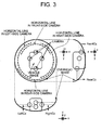
- FIG. 3 is a view for explaining a misalignment of the horizontal lines among the overhead images based on images of the respective camera.
- f(r) c*r(R- ⁇ (R 2 -r 2 )
- the front-side camera 10 and the rear-side camera 20 have the largest difference in arrangement height and, accordingly, misalignment between the position of the horizontal line in the overhead image of the front-side camera 10 and the position of the horizontal line in the overhead image of the rear-side camera 20 is largest.
- FIG. 4 is a view for explaining an overhead image in which the height direction of the shape thereof is made proportional to the arrangement height of the camera.
- the overhead image f(r) is represented by a calculation formula in which it is made proportional to an arrangement height C z of the camera.
- the DefC z is a standard arrangement height of the camera.
- a distance between the horizontal line position and the center of the overhead image is the same in all the overhead images.
- the positions of the horizontal lines are aligned.
- the following describes a modification that reduces a feeling of strangeness in displaying the overhead image based on the image of each camera not by freely changing the viewpoint/line-of-sight but by changing the shape of the overhead image.
- FIG. 5 is a view for explaining an overhead image having a ground plane area in the radial direction from the center of the vehicle and having a changed aspect ratio.
- g(r) 0 (r ⁇ w)
- the ground plane area may be defined by longitudinal and lateral directions, not by the radial direction r.
- FIG. 6 is a view explaining an overhead view having the ground plane area in the longitudinal and lateral directions from the center of the vehicle and having a changed aspect ratio.
- the ground plane may be defined by combination of the radial direction r, x-direction, and y-direction.
- a center of the overhead image shape may be shifted from the vehicle center.
- FIGS. 7A and 7B are views for explaining an example in which the overhead image shape is arbitrarily specified.
- an overhead image shape g(r) is plotted for each change of the radial direction r to be arbitrarily specified as linear interpolation or spline interpolation.
- a plot order is previously determined, and a relationship between a distance in the radial direction and camera arrangement height is plotted, not for each change of the radial direction r, but arbitrarily, for specification of the overhead image shape as linear interpolation or spline interpolation.
- a value of the overhead image obtained in this case also changes in proportion to the camera arrangement height.
- FIG. 8 is a flowchart illustrating a processing flow up to display of the overhead image.
- step S81 it is determined whether it is the first execution of the processing up to display of the overhead image or the viewpoint/line-of-sight is changed.
- step S81 When Yes is obtained in step S81, information of the viewpoint/line-of-sight is acquired (step S82). When NO is obtained in step S81, the flow shifts to step S85.
- the overhead LUT creator 53 creates, based on the camera calibration data and viewpoint/line-of-sight information, the coordinate conversion lookup table for viewpoint conversion of the image taken by the camera (step S84). Details of the lookup table creation processing will be described later.
- the overhead image generator 54 acquires the image from each camera (step S85).
- the overhead image generator 54 performs coordinate conversion for the camera image based on the lookup table and then synthesizes the obtained coordinate-converted images to generate an overhead image (step S86).
- an overhead image in which the horizontal lines of the camera images are aligned is generated.
- the overhead image in which the horizontal lines of the camera images are aligned is displayed on the display device 60 (step S87).
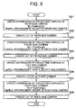
- FIG. 9 is a flowchart illustrating a flow of lookup table creation processing.
- step S92 a lookup table for the rear-side camera is created.
- step S94 a lookup table for the front-side camera is created.
- step S96 a lookup table for the left-side camera is created.
- step S98 a lookup table for the right-side camera is created (step S98), and the lookup table creation processing is ended.
- a configuration of the overhead image generation apparatus 1 according to the second embodiment is basically the same as that of the overhead image generation apparatus 1 according to the first embodiment.
- the second embodiment relates an alignment of horizontal lines in the overhead images in a case where a viewpoint position is arbitrarily set.
- FIG. 10 is a view for explaining an overhead image in a case where a viewpoint position is arbitrarily set in the second embodiment.
- Projection conversion is required in order to project (display) a three-dimensional world onto a two-dimensional projection surface.
- the projection method roughly includes parallel projection and perspective projection.
- parallel projection objects of the same size are displayed in the same size irrespective of a distance from the viewpoint. For example, when an x-y plane is set as the projection surface, a z coordinate is set to 0.
- the perspective projection even when two objects are the same in size, a distant one looks small, and near one looks large.
- parallel ridgelines when parallel ridgelines are extended, they cross at the same point (vanishing point), and the number of the vanishing points changes from one to three depending on the line-of-sight direction.
- the line-of-sight direction can freely be controlled, the number of the vanishing point is three, in general.
- the horizontal line positions are not aligned even when the first embodiment is applied.
- a camera serving as a reference and a point on the horizontal line serving as a boundary of the reference camera and the position of the horizontal line of another camera at the boundary of the reference camera is set to be seen in the same position as that of the horizontal line in the reference camera when viewed from the virtual viewpoint in the perspective projection conversion.
- the position of the horizontal line of another camera is set to be seen in the same position as that of the horizontal line in the reference camera in the line-of-sight direction. That is, an extended line of the line-of-sight direction passing through the point on the horizontal line is made coincide with the horizontal line in the another camera.
- the front-side camera is used as the reference camera
- the right-side camera is used as the another camera at the boundary of the reference camera.
- b which is a longitudinal constant may be changed for the front-side camera and the rear-side camera, while a which is a lateral constant may be changed for the left-side camera and the right-side camera.
- b which is the longitudinal constant may be changed, while when the position corresponding to the boundary between the two cameras is near the left-side camera and the right-side camera, a which is the lateral constant may be changed.
- a ratio between a and b may be changed based on the line-of-sight direction according to a ratio between the lateral and longitudinal directions thereof.
- the line-of-sight direction is (d, e, f)
- calculation may be made such that the lateral position of the horizontal line to be aligned is not changed as viewed from the virtual viewpoint.
- the viewpoint is (X 0 , y 0 , z 0 ) and line-of-sight direction is (x 1 , y 1 , z 1 )
- calculation may be made such that (x-x 0 )/x 1 - (y-y 0 )/y 1 is maintained.
- the overhead image having a shape in which the calculation formula of the radial direction r is different for each camera may be calculated by fixing a of one camera and b of another camera and changing b of the one camera and a of the another camera so as to align the positions of the horizontal lines.
- the overhead image having a shape in which the calculation formula of the radial direction r is different for each camera may be calculated by fixing b of one camera and a of another camera and changing a of the one camera and b of the another camera so as to align the positions of the horizontal lines. Further, calculation may be made such that the lateral position of the horizontal line to be aligned is not changed as viewed from the virtual viewpoint.
- the overhead image having a shape in which the calculation formula of the radial direction r is different for each camera may be calculated such that (x-x 0 )/x 1 - (y-y 0 )/y 1 is maintained.
- the overhead view may have the ground plane area in the radial direction from the vehicle center, as illustrated in FIG. 5 .
- the overhead view may have the ground plane area in both the lateral and longitudinal directions, as illustrated in FIG. 6 .
- the second embodiment in a case where images of the ground area and the horizontal line area are simultaneously displayed, it is possible to align the display positions of the horizontal lines even when the arrangement heights of cameras are different.
- the four cameras front-side camera, rear-side camera, right-side camera, and left-side camera
- the present invention is not limited to this, and the number of the cameras may be at least two or more.
- the misalignment of the horizontal lines which may cause a feeling of strangeness when the images of the ground area and the horizontal line area are simultaneously displayed by synthesizing the images of the plurality of cameras is corrected on the display image, whereby the overhead image can be displayed in a state free from misalignment of the horizontal lines.
Landscapes
- Engineering & Computer Science (AREA)
- Multimedia (AREA)
- Signal Processing (AREA)
- Physics & Mathematics (AREA)
- General Physics & Mathematics (AREA)
- Theoretical Computer Science (AREA)
- Mechanical Engineering (AREA)
- Closed-Circuit Television Systems (AREA)
- Image Processing (AREA)
- Image Analysis (AREA)
Applications Claiming Priority (1)
| Application Number | Priority Date | Filing Date | Title |
|---|---|---|---|
| JP2015111235A JP2016225865A (ja) | 2015-06-01 | 2015-06-01 | 俯瞰画像生成装置 |
Publications (2)
| Publication Number | Publication Date |
|---|---|
| EP3101621A2 true EP3101621A2 (fr) | 2016-12-07 |
| EP3101621A3 EP3101621A3 (fr) | 2016-12-21 |
Family
ID=55315316
Family Applications (1)
| Application Number | Title | Priority Date | Filing Date |
|---|---|---|---|
| EP16153693.3A Withdrawn EP3101621A3 (fr) | 2015-06-01 | 2016-02-01 | Appareil de génération d'image aérienne |
Country Status (4)
| Country | Link |
|---|---|
| US (1) | US9852494B2 (fr) |
| EP (1) | EP3101621A3 (fr) |
| JP (1) | JP2016225865A (fr) |
| CN (1) | CN106204521A (fr) |
Cited By (1)
| Publication number | Priority date | Publication date | Assignee | Title |
|---|---|---|---|---|
| CN112365549A (zh) * | 2021-01-12 | 2021-02-12 | 腾讯科技(深圳)有限公司 | 车载相机的姿态校正方法、装置和存储介质及电子装置 |
Families Citing this family (8)
| Publication number | Priority date | Publication date | Assignee | Title |
|---|---|---|---|---|
| JP6669569B2 (ja) * | 2016-04-04 | 2020-03-18 | アルパイン株式会社 | 車両用周辺監視装置 |
| WO2017190092A1 (fr) * | 2016-04-29 | 2017-11-02 | Faraday&Future Inc. | Système pour fournir un équilibre de couleur dans un dispositif d'affichage d'automobile |
| JP7039879B2 (ja) * | 2017-08-03 | 2022-03-23 | 株式会社アイシン | 表示制御装置 |
| JP6958163B2 (ja) | 2017-09-20 | 2021-11-02 | 株式会社アイシン | 表示制御装置 |
| JP7314518B2 (ja) * | 2019-02-06 | 2023-07-26 | 株式会社アイシン | 周辺監視装置 |
| JP7559535B2 (ja) | 2020-12-14 | 2024-10-02 | 株式会社デンソー | 車両用表示制御装置及び車両用表示制御方法 |
| JP7593101B2 (ja) | 2020-12-25 | 2024-12-03 | 株式会社デンソー | 画像生成装置、画像生成方法 |
| US12366055B2 (en) * | 2021-03-25 | 2025-07-22 | Hitachi Construction Machinery Co., Ltd. | Information presentation device |
Citations (1)
| Publication number | Priority date | Publication date | Assignee | Title |
|---|---|---|---|---|
| WO2014174884A1 (fr) * | 2013-04-24 | 2014-10-30 | 住友重機械工業株式会社 | Dispositif de génération d'images à traiter, procédé de génération d'images à traiter, et système d'aide à l'exploitation |
Family Cites Families (18)
| Publication number | Priority date | Publication date | Assignee | Title |
|---|---|---|---|---|
| EP2267656A3 (fr) * | 1998-07-31 | 2012-09-26 | Panasonic Corporation | Appareil d'affichage d'images et procédé d'affichage d'images |
| EP1850595B1 (fr) * | 2005-02-15 | 2016-07-13 | Panasonic Intellectual Property Management Co., Ltd. | Dispositif et procede de surveillance de peripherie |
| JP4956799B2 (ja) | 2006-05-09 | 2012-06-20 | 日産自動車株式会社 | 車両周辺画像提供装置及び車両周辺画像提供方法 |
| JP4927512B2 (ja) | 2006-12-05 | 2012-05-09 | 株式会社日立製作所 | 画像生成装置 |
| JP5182042B2 (ja) | 2008-11-28 | 2013-04-10 | 富士通株式会社 | 画像処理装置、画像処理方法及びコンピュータプログラム |
| JP4951639B2 (ja) | 2009-03-02 | 2012-06-13 | 日立建機株式会社 | 周囲監視装置を備えた作業機械 |
| JP5627253B2 (ja) * | 2009-05-29 | 2014-11-19 | 富士通テン株式会社 | 画像処理装置、電子装置、および、画像処理方法 |
| CN102577372B (zh) * | 2009-09-24 | 2015-06-10 | 松下电器产业株式会社 | 驾驶辅助显示装置 |
| JP5491235B2 (ja) * | 2010-03-02 | 2014-05-14 | 東芝アルパイン・オートモティブテクノロジー株式会社 | カメラキャリブレーション装置 |
| JP5451497B2 (ja) * | 2010-04-08 | 2014-03-26 | パナソニック株式会社 | 運転支援表示装置 |
| JP5699679B2 (ja) * | 2011-02-24 | 2015-04-15 | 富士通セミコンダクター株式会社 | 画像処理装置、画像処理システム、及び画像処理方法 |
| CN102164274B (zh) * | 2011-04-26 | 2013-11-06 | 石黎 | 一种视场可变的车载虚拟全景系统 |
| DE112012004354T5 (de) * | 2011-10-18 | 2014-07-10 | Hitachi Construction Machinery Co., Ltd. | Vorrichtung zum Überwachen der Umgebung von Maschinerie |
| JP5898475B2 (ja) * | 2011-11-28 | 2016-04-06 | クラリオン株式会社 | 車載カメラシステム及びその較正方法、及びその較正プログラム |
| US9013558B2 (en) * | 2012-07-02 | 2015-04-21 | Sony Corporation | System and method for alignment of stereo views |
| JP6099333B2 (ja) * | 2012-08-30 | 2017-03-22 | 富士通テン株式会社 | 画像生成装置、画像表示システム、パラメータ取得装置、画像生成方法及びパラメータ取得方法 |
| JP5904093B2 (ja) * | 2012-10-30 | 2016-04-13 | 株式会社デンソー | 車載画像生成装置 |
| US9900583B2 (en) * | 2014-12-04 | 2018-02-20 | Futurewei Technologies, Inc. | System and method for generalized view morphing over a multi-camera mesh |
-
2015
- 2015-06-01 JP JP2015111235A patent/JP2016225865A/ja not_active Abandoned
- 2015-12-18 CN CN201510958910.5A patent/CN106204521A/zh not_active Withdrawn
-
2016
- 2016-02-01 EP EP16153693.3A patent/EP3101621A3/fr not_active Withdrawn
- 2016-02-03 US US15/014,186 patent/US9852494B2/en not_active Expired - Fee Related
Patent Citations (2)
| Publication number | Priority date | Publication date | Assignee | Title |
|---|---|---|---|---|
| WO2014174884A1 (fr) * | 2013-04-24 | 2014-10-30 | 住友重機械工業株式会社 | Dispositif de génération d'images à traiter, procédé de génération d'images à traiter, et système d'aide à l'exploitation |
| EP2991343A1 (fr) * | 2013-04-24 | 2016-03-02 | Sumitomo Heavy Industries, Ltd. | Dispositif de génération d'images à traiter, procédé de génération d'images à traiter, et système d'aide à l'exploitation |
Cited By (1)
| Publication number | Priority date | Publication date | Assignee | Title |
|---|---|---|---|---|
| CN112365549A (zh) * | 2021-01-12 | 2021-02-12 | 腾讯科技(深圳)有限公司 | 车载相机的姿态校正方法、装置和存储介质及电子装置 |
Also Published As
| Publication number | Publication date |
|---|---|
| US20160350894A1 (en) | 2016-12-01 |
| US9852494B2 (en) | 2017-12-26 |
| CN106204521A (zh) | 2016-12-07 |
| EP3101621A3 (fr) | 2016-12-21 |
| JP2016225865A (ja) | 2016-12-28 |
Similar Documents
| Publication | Publication Date | Title |
|---|---|---|
| EP3101621A2 (fr) | Appareil de génération d'image aérienne | |
| US10721442B2 (en) | Surround view monitor apparatus | |
| KR102253553B1 (ko) | 사발형 이미징 시스템에서의 물체 가시화 | |
| EP3304498B1 (fr) | Systèmes et procédés de production d'une vue combinée à partir d'appareils photo à ultra-grand-angle | |
| CA2888943C (fr) | Systeme a realite augmentee et procede de positionnement et de cartographie | |
| US9716870B2 (en) | Image processor, image processing method, and image projector | |
| US9013559B2 (en) | System, method and program for capturing images from a virtual viewpoint | |
| US9317924B2 (en) | Information processing apparatus, three-dimensional position calculation method, and program | |
| CN106447602B (zh) | 一种图像拼接方法及装置 | |
| US10027949B2 (en) | Image processing apparatus, image processing method, and recording medium | |
| US10388007B2 (en) | Image processing method and image processing device | |
| JP5146330B2 (ja) | 車両用道路標示認識装置 | |
| CN104937634B (zh) | 用于生成环绕视图的方法和系统 | |
| US10412359B2 (en) | Method for generating a virtual image of vehicle surroundings | |
| JP6810873B2 (ja) | 電子ディスプレイの前方または上に投影されて見える仮想3次元画像を作製するためのシステム、方法、およびソフトウェア | |
| US20200329227A1 (en) | Information processing apparatus, information processing method and storage medium | |
| US20130314533A1 (en) | Data deriving apparatus | |
| CN114063295A (zh) | 增强现实图像的动态调整 | |
| JP4819834B2 (ja) | 立体映像処理装置及び立体映像処理方法 | |
| US9215441B2 (en) | Image processing apparatus, non-transitory computer readable recording medium, and image processing method | |
| JP2019029721A (ja) | 画像処理装置、画像処理方法およびプログラム | |
| KR102917059B1 (ko) | 삼각형 기반의 선택적 워핑을 통한 가상 시점 영상 합성 방법 및 장치 | |
| JP2013207622A (ja) | キャリブレーション装置及びキャリブレーション方法 | |
| KR101588409B1 (ko) | 마커를 이용하여 표출되는 증강 현실 객체에 대한 입체 사운드 제공 방법 | |
| US20140362197A1 (en) | Image processing device, image processing method, and stereoscopic image display device |
Legal Events
| Date | Code | Title | Description |
|---|---|---|---|
| PUAI | Public reference made under article 153(3) epc to a published international application that has entered the european phase |
Free format text: ORIGINAL CODE: 0009012 |
|
| STAA | Information on the status of an ep patent application or granted ep patent |
Free format text: STATUS: REQUEST FOR EXAMINATION WAS MADE |
|
| PUAL | Search report despatched |
Free format text: ORIGINAL CODE: 0009013 |
|
| 17P | Request for examination filed |
Effective date: 20160201 |
|
| AK | Designated contracting states |
Kind code of ref document: A2 Designated state(s): AL AT BE BG CH CY CZ DE DK EE ES FI FR GB GR HR HU IE IS IT LI LT LU LV MC MK MT NL NO PL PT RO RS SE SI SK SM TR |
|
| AX | Request for extension of the european patent |
Extension state: BA ME |
|
| AK | Designated contracting states |
Kind code of ref document: A3 Designated state(s): AL AT BE BG CH CY CZ DE DK EE ES FI FR GB GR HR HU IE IS IT LI LT LU LV MC MK MT NL NO PL PT RO RS SE SI SK SM TR |
|
| AX | Request for extension of the european patent |
Extension state: BA ME |
|
| RIC1 | Information provided on ipc code assigned before grant |
Ipc: G06T 3/40 20060101AFI20161114BHEP |
|
| STAA | Information on the status of an ep patent application or granted ep patent |
Free format text: STATUS: EXAMINATION IS IN PROGRESS |
|
| 17Q | First examination report despatched |
Effective date: 20170901 |
|
| RAP1 | Party data changed (applicant data changed or rights of an application transferred) |
Owner name: ALPINE ELECTRONICS, INC. |
|
| RAP1 | Party data changed (applicant data changed or rights of an application transferred) |
Owner name: TOSHIBA INFRASTRUCTURE SYSTEMS & SOLUTIONS CORPORA |
|
| STAA | Information on the status of an ep patent application or granted ep patent |
Free format text: STATUS: THE APPLICATION HAS BEEN WITHDRAWN |
|
| 18W | Application withdrawn |
Effective date: 20180710 |