EP3101636B1 - Vérification de plan de maintenance au moyen de dispositifs de commande d'automatisation par l'intermédiaire d'un motif d'utilisation analytique de données de grande taille - Google Patents
Vérification de plan de maintenance au moyen de dispositifs de commande d'automatisation par l'intermédiaire d'un motif d'utilisation analytique de données de grande taille Download PDFInfo
- Publication number
- EP3101636B1 EP3101636B1 EP16169816.2A EP16169816A EP3101636B1 EP 3101636 B1 EP3101636 B1 EP 3101636B1 EP 16169816 A EP16169816 A EP 16169816A EP 3101636 B1 EP3101636 B1 EP 3101636B1
- Authority
- EP
- European Patent Office
- Prior art keywords
- automation
- automation device
- devices
- processor
- wear
- Prior art date
- Legal status (The legal status is an assumption and is not a legal conclusion. Google has not performed a legal analysis and makes no representation as to the accuracy of the status listed.)
- Active
Links
Images


Classifications
-
- G—PHYSICS
- G05—CONTROLLING; REGULATING
- G05B—CONTROL OR REGULATING SYSTEMS IN GENERAL; FUNCTIONAL ELEMENTS OF SUCH SYSTEMS; MONITORING OR TESTING ARRANGEMENTS FOR SUCH SYSTEMS OR ELEMENTS
- G05B23/00—Testing or monitoring of control systems or parts thereof
- G05B23/02—Electric testing or monitoring
- G05B23/0205—Electric testing or monitoring by means of a monitoring system capable of detecting and responding to faults
- G05B23/0259—Electric testing or monitoring by means of a monitoring system capable of detecting and responding to faults characterized by the response to fault detection
- G05B23/0283—Predictive maintenance, e.g. involving the monitoring of a system and, based on the monitoring results, taking decisions on the maintenance schedule of the monitored system; Estimating remaining useful life [RUL]
-
- G—PHYSICS
- G08—SIGNALLING
- G08B—SIGNALLING SYSTEMS, e.g. PERSONAL CALLING SYSTEMS; ORDER TELEGRAPHS; ALARM SYSTEMS
- G08B25/00—Alarm systems in which the location of the alarm condition is signalled to a central station, e.g. fire or police telegraphic systems
- G08B25/14—Central alarm receiver or annunciator arrangements
-
- G—PHYSICS
- G08—SIGNALLING
- G08B—SIGNALLING SYSTEMS, e.g. PERSONAL CALLING SYSTEMS; ORDER TELEGRAPHS; ALARM SYSTEMS
- G08B29/00—Checking or monitoring of signalling or alarm systems; Prevention or correction of operating errors, e.g. preventing unauthorised operation
-
- G—PHYSICS
- G08—SIGNALLING
- G08B—SIGNALLING SYSTEMS, e.g. PERSONAL CALLING SYSTEMS; ORDER TELEGRAPHS; ALARM SYSTEMS
- G08B29/00—Checking or monitoring of signalling or alarm systems; Prevention or correction of operating errors, e.g. preventing unauthorised operation
- G08B29/02—Monitoring continuously signalling or alarm systems
-
- H—ELECTRICITY
- H04—ELECTRIC COMMUNICATION TECHNIQUE
- H04N—PICTORIAL COMMUNICATION, e.g. TELEVISION
- H04N7/00—Television systems
- H04N7/18—Closed-circuit television [CCTV] systems, i.e. systems in which the video signal is not broadcast
- H04N7/181—Closed-circuit television [CCTV] systems, i.e. systems in which the video signal is not broadcast for receiving images from a plurality of remote sources
-
- G—PHYSICS
- G08—SIGNALLING
- G08B—SIGNALLING SYSTEMS, e.g. PERSONAL CALLING SYSTEMS; ORDER TELEGRAPHS; ALARM SYSTEMS
- G08B29/00—Checking or monitoring of signalling or alarm systems; Prevention or correction of operating errors, e.g. preventing unauthorised operation
- G08B29/18—Prevention or correction of operating errors
Definitions
- This application relates to security systems and more particular to maintaining such systems.
- Home or building automation systems that serve and protect people and assets within secured areas (e.g., a home or other residence, commercial area, etc.) are known. Such systems are typically based upon the use of one or more controlled devices and may include one or more sensors that detect threats within the area.
- Threats to people and assets may originate from any of number of different sources. For example, a fire may kill or injure occupants who have become trapped by a fire in a home or a commercial building. Similarly, carbon monoxide from a fire may kill people in their sleep.
- an unauthorized intruder such as a burglar
- sensors may be placed in different areas based upon the respective uses of those areas. For example, if people are present during some portions of a normal day and not at other times, then sensors may be placed along a periphery of the space to provide protection while the space is occupied while additional sensors may be placed within an interior of the space and used when the space is not occupied.
- threat detectors are connected to a local control panel.
- the control panel may sound a local audible alarm.
- the control panel may also send a signal to a central monitoring station.
- US Patent Publication US006646564B1 describes a system for remote monitoring and control of equipment such as cryogenic freezers, using sensors and standards compared by a processor.
- the system includes both automatic alteration of settings and alerting of personnel.
- FIG. 1 is a block diagram of a home or building automation system 10 shown generally in accordance with an illustrated embodiment. Included within the building automation system are a number of building automation devices 12. For example, at least some of the building automation devices may be embodied as sensors or imaging devices 14, 16 that detect threats within a secured geographic area 18. Other of the building automation devices may be embodied as access control devices that control access into or out of the secured area or may be environmental control devices that control the environment of the secured area.
- the sensors may be embodied in any of a number of different forms.
- at least some of the sensors may be switches or vibration sensors placed on the doors and windows along a periphery of the secured area.
- Other of the sensors may be passive infrared (PIR) sensors located in the interior of the secured area that detect intruders who have been able to circumvent the sensors along the periphery.
- PIR passive infrared
- the sensors may include one or more environmental detectors that detect threats to the safety of human occupants.
- some of the detectors may be fire detectors while others may be toxic gas detectors.
- the building automation devices may include one or more imaging devices. For example, one or more cameras may capture images within the secured area.
- a digital video recorder may record those images on a continuous basis or only upon activation of an intrusion sensor.
- a control panel 24 may be located within the secured area or elsewhere that monitors the sensors. Upon activation of one of the sensors, the control panel may send an alarm message to a central monitoring station 26. In response, the central monitoring station may respond by summoning help (e.g., fire department, police, etc.).
- help e.g., fire department, police, etc.
- the access and environmental control devices may also be embodied in any of a number of different forms.
- the access control devices may be card readers or automatic door controllers that mechanically open and close doors that provide access into and out of the secured area or portions thereof.
- the access control devices may be magnetic locks that lock or unlock those doors and that control the opening of those doors.
- environmental control devices may control lighting, heating, ventilating, air conditioning (HVAC) units, etc. within the secured area.
- HVAC heating, ventilating, air conditioning
- a user interface 28 allows a human user to control the building automation system.
- the user may enter a personal identification number (PIN) and function key through a keyboard 32 to arm security features provided by the building automation system.
- Status information e.g., armed, disarmed, etc. may be shown on a display 30.
- the automation devices and user interface may be one or more processor apparatus (processors) 34, 36, each operating under control of one or more computer programs 38, 40 loaded from a non-transitory computer readable medium (memory) 42.
- processor apparatus processors
- computer programs 38, 40 loaded from a non-transitory computer readable medium (memory) 42.
- reference to a step of a computer program is also reference to the processor that executed that step.
- a status processor may monitor the keyboard for input from the user. Upon entry of a valid PIN by the user along with activation of an arm key, the status processor may cause a security system portion of the building automation system to enter an armed state. Similarly, the user may enter the appropriate codes to activate and deactivate various building automation devices such as heating ventilating air conditioning (HVAC) equipment, lighting or a home entertainment system.
- HVAC heating ventilating air conditioning
- an alarm processor may monitor each of the sensors for threats. Upon activation of one of the sensors, the alarm processor may compose and send an alarm message to the central monitoring station.
- the security system or a separate entry control system may monitor a set of card readers on the entrances and exits of the secured area.
- an entry control processor may compare an identifier read from the card with a set of identifiers of authorized users saved in the memory of the control panel. If a match is found, the entry control processor may activate a magnetic lock to unlock a corresponding door and activate a door opening device to automatically move the door to a fully open position. After a predetermined period of time sufficient for the user to enter, the entry control processor closes the door.
- one or more device usage or tracking processors of a failure evaluation subsystem determines a set of performance parameters for each of the building automation devices. Based upon changes in the performance parameters, the tracking processor is able to detect performance degradation over time and the need for corrective action. Based upon the degradation over time, the tracking or a related processor may detect the possibility of a potential failure of the device and present recommendation for ameliorating the potential failure to an authorized human user of the automation system.
- the tracking processor may determine the duration of time necessary for a door opener to move a door from a fully closed to a fully open position and from a fully open to a fully closed position.
- the determined duration of time may be compared with a criteria found within a criteria file 44, 46 of the door opener. If the determined time exceeds the criteria, then the processor may retrieve a message that is presented through the display of the user interface.
- the message may include an identifier of the door opener, its location and an indicator that the door is opening too slow.
- the message may further give an indication of possible remedial actions such as greasing or cleaning the moving parts (e.g., the track) of the door opener.
- the criteria for identifying the need for remedial action may be based upon any of a number of different sources of information.
- the criteria file is based upon a set of operational specifications originally provided by a manufacturer of the device (e.g., the door opener).
- the criteria may be based upon measured parameters obtained when the device was originally installed.
- an outside temperature sensor may be used to detect or otherwise gauge the effectiveness of the HVAC unit in the time it takes to cool or heat the space under a specific set of conditions.
- a tracking processor to track and detect the degradation of performance and to advise on ways of correcting the performance offers a number of advantages. For example, there is often a very large number of automation devices installed in some large premises. These devices/equipment wear out slowly and steadily depending on the usage. The maintenance of this equipment may be ignored by maintenance personnel or the operator due to the inherent human inability to perceive small changes over long periods of time.
- the system of FIG. 1 analyzes the key performance parameters of each device of various systems (e.g., access control, video, HVAC, lighting, etc.) from the recorded events.
- the system generates customized maintenance activities by matching the performance parameters with the equipment's warranty information and environmental measurements from the area in which the device is placed. Additional information can be derived from a Building Information Model (BIM) and weather feeds.
- BIM Building Information Model
- the time elapsed between the energize or deenergize event and the door position sensor providing an open or closed signal gives the time the door takes to respond for opening and closing.
- This time interval is the performance parameter that can be monitored by the system for degradation.
- the proposed system correlates contextual information (e.g., temperature) where equipment is deployed, etc. along with usage statistics to suggest specific maintenance tasks such as providing increased thermal insulation, frequent cleaning of devices placed outdoors, etc.
- contextual information e.g., temperature
- the system of FIG. 1 also detects nuisance alarms from analysis of alarm logs by a nuisance alarm processor over a period of time.
- the recommendation may be limited to a general statement that the repeated alarms indicate a potential failure of the sensor.
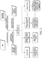
- the failure subsystem has a data processing unit which receives data from multiple sources (e.g., BIM, weather feeds, warranty information, security system, etc.).
- the data processing unit analyzes the data from the different sources and suggests different actions to the user.
- the failure system also contains a number of sub-processes such as a swap processor, warranty information processor, nuisance alarm processor, etc., that specifically look for pattern changes in different performance parameters and suggest appropriate maintenance actions.
- the failure system has a set of criteria that can be changed at the convenience of a system engineer.
- the system presents these performance parameters (i.e., criteria) to the system engineer who can then create his/her own rules and conditions for triggering custom maintenance actions.
- the failure detection system has a number of advantages over conventional home or building automation systems. For example, the system reduces the reliance on the system engineer's ability to perceive the gradual degradation of the device over a long period of usage. By providing this level of analysis, the service engineer can analyze the problem in an intelligent way.
- the system helps the client to save money by using devices optimally by comparing device performance with manufacturer's specification and, where there is a difference, prompting to correct any deficiencies that cause the difference.
- the reasons for differences in performance parameters can be identified and used to better position the devices in order to ameliorate environmental effects thereby increasing the lifetime.
- By planning maintenance cycles based on real usage of devices maintenance effectiveness increases and manual effort is reduced.
- the failure detection system may be used in large industrial/commercial/residential buildings with large numbers of installed security devices.
- the system may reduce the cost of maintaining the large number of devices by providing optimum/efficient anticipatory maintenance plans.
- the system may compare the statistics of the same type of devices used for the same purpose among different brands to achieve an overall maintenance cost of each brand.
- the system may also compare the performances of different brands to arrive at the performance of devices from each brand, thereby helping the customer to identify the better brand for future purchases/investments.
- the system can also be used to generate an anticipatory maintenance plan for other devices such as cameras, PIRs, lighting systems, DVRs and projectors based on the data analysis to achieve similar benefits.
- the system Based upon the analysis of recorded events, the system identifies the least and most used equipment such as doors, readers or cameras. This may be overlaid in a graphical format over a map of the secured area based upon BIM information.
- the system suggests a method of increasing the service warranties of devices based upon usage by providing a better operating environment for the device.
- the system also provides a basis for intimating a service/replacement plan based upon average maintenance time/costs.
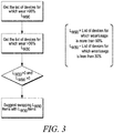
- the system also provides a processor that suggests swapping of devices, if one of the devices fails or if some of the devices are underutilized. For example (see FIG. 3 ), the system will extract a list of devices for which the wear or usage has crossed the 90% of its manufacture specified limit. Then, it will extract a list of similar type of devices which has a wear or usage below 30% of its manufacturer specified limit. From both lists, the system will suggest swapping the most used devices with the least used devices. This can prolong the life of devices.
- the failure detection system may also compare the rate of wear for devices of two different brands in similar usage and environment. If one brand's device wears faster than the other, then the proposed system suggests using the better brand.
- the failure detection system may calculate the rate of wear of devices and forecast when the total usage nears the manufacturer's defined lifetime limit for the device.
- the system reports the list of devices reaching their limit in the near future, which could be helpful for use for a procurement plan. For example (see FIG. 4 ), the system will calculate the total wear or usage of all of the devices and then will calculate the remaining usage based on the manufacturer specified limit. If the remaining wear or age expires within a pre-defined period of time, then the system will notify the operator to procure devices in advance.
- the system will raise an alert if the device's performance falls below specified limits before the manufacture guaranteed time frame. This allows the device can be replaced well before the warranty period ends.
- the system suggests using higher grade products (e.g., more rugged doors, higher strength materials, etc.) in places where high wear and tear is detected. This reduces costs by increasing the time between maintenance intervals.
- higher grade products e.g., more rugged doors, higher strength materials, etc.
- the system suggests to manually check specific devices if they are used sparingly. This can reduce the future failures due to negligence or undetected deterioration due to non-use.
- the system can track the total time a PIR sensor or vibration sensor is/was kept armed. This can be used to suggest a more frequent check on battery life of these sensors.
- the system can detect that devices like projectors and lighting systems are being used heavily in one area of a building and are scarcely used in another area. This could be used to suggest swapping these devices to extend the device's lifetime.
- the system can monitor top level parameters like camera frame rate, DVR hard disk space utilization. This information can be used to suggest corrective actions or configuration changes for increasing the device life time without compromising the desired functionality.
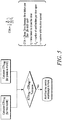
- the system detects the change. The system then compares the current month's data with that of the previous months and notifies the user that there has been a sudden change in usage for that particular device (see FIG. 5 ).
Landscapes
- Physics & Mathematics (AREA)
- General Physics & Mathematics (AREA)
- Engineering & Computer Science (AREA)
- Computer Security & Cryptography (AREA)
- Business, Economics & Management (AREA)
- Emergency Management (AREA)
- Automation & Control Theory (AREA)
- Multimedia (AREA)
- Signal Processing (AREA)
- Alarm Systems (AREA)
- Management, Administration, Business Operations System, And Electronic Commerce (AREA)
Claims (7)
- Système comprenant :une pluralité de dispositifs d'automatisation situés dans une zone géographique sécurisée, où au moins une partie de la pluralité de dispositifs d'automatisation détectent des menaces dans la zone géographique sécurisée ;un système d'automatisation qui surveille au moins une partie de la pluralité de dispositifs d'automatisation pour les menaces dans la zone géographique sécurisée et qui signale les menaces à une station de surveillance centrale ;un processeur d'un premier dispositif d'automatisation de la pluralité de dispositifs d'automatisation qui est installé à un premier emplacement et qui mesure l'usure du premier dispositif d'automatisation lui-même et signale l'usure mesurée à un panneau de commande du système d'automatisation ;un processeur d'un deuxième dispositif d'automatisation de la pluralité de dispositifs d'automatisation qui est installé à un deuxième emplacement et qui mesure l'usure du deuxième dispositif d'automatisation lui-même et signale l'usure mesurée au panneau de commande du système d'automatisation ; etun processeur du panneau de commande qui compare l'usure mesurée du premier dispositif d'automatisation à un ou plusieurs critères, détermine que l'usure mesurée du premier dispositif d'automatisation dépasse un premier seuil, compare l'usure mesurée du deuxième dispositif d'automatisation à un ou plusieurs critères, détermine que l'usure mesurée du deuxième dispositif d'automatisation est inférieure à un deuxième seuil, et présente un avis suggérant de permuter le premier dispositif d'automatisation avec le deuxième dispositif d'automatisation de manière à ce que le premier dispositif d'automatisation soit installé au deuxième emplacement et que le deuxième dispositif d'automatisation soit installé au premier emplacement, où le premier seuil est supérieur au deuxième seuil.
- Système selon la revendication 1, dans lequel le ou les critères comprennent les spécifications techniques du premier dispositif d'automatisation.
- Système selon la revendication 2, dans lequel le processeur du premier dispositif d'automatisation mesure un paramètre environnemental du premier dispositif d'automatisation.
- Système selon la revendication 3, dans lequel le processeur du panneau de commande compare le paramètre environnemental du premier dispositif d'automatisation à un paramètre correspondant des spécifications techniques du premier dispositif d'automatisation, et avertit un utilisateur humain autorisé lorsque le paramètre environnemental dépasse le paramètre correspondant des spécifications techniques.
- Système selon la revendication 4, dans lequel le paramètre environnemental comprend un paramètre parmi les suivants : qualité de l'air de température et humidité.
- Système selon la revendication 1, dans lequel la pluralité de dispositifs d'automatisation comprennent un ou plusieurs dispositifs parmi les suivants : un ouvre-porte, une serrure magnétique, un dispositif d'entrée d'état, une caméra, un détecteur infrarouge passif (PIR), un capteur de vibrations et un enregistreur vidéo numérique (DVR).
- Système selon la revendication 6, dans lequel le premier dispositif d'automatisation est l'ouvre-porte.
Applications Claiming Priority (1)
| Application Number | Priority Date | Filing Date | Title |
|---|---|---|---|
| US14/730,952 US10948906B2 (en) | 2015-06-04 | 2015-06-04 | Maintenance plan forecast using automation control devices' usage pattern through big data analytics |
Publications (2)
| Publication Number | Publication Date |
|---|---|
| EP3101636A1 EP3101636A1 (fr) | 2016-12-07 |
| EP3101636B1 true EP3101636B1 (fr) | 2018-09-26 |
Family
ID=56008510
Family Applications (1)
| Application Number | Title | Priority Date | Filing Date |
|---|---|---|---|
| EP16169816.2A Active EP3101636B1 (fr) | 2015-06-04 | 2016-05-16 | Vérification de plan de maintenance au moyen de dispositifs de commande d'automatisation par l'intermédiaire d'un motif d'utilisation analytique de données de grande taille |
Country Status (5)
| Country | Link |
|---|---|
| US (2) | US10948906B2 (fr) |
| EP (1) | EP3101636B1 (fr) |
| CN (1) | CN106251595A (fr) |
| CA (1) | CA2930540C (fr) |
| ES (1) | ES2699899T3 (fr) |
Cited By (1)
| Publication number | Priority date | Publication date | Assignee | Title |
|---|---|---|---|---|
| DE102023204427A1 (de) | 2023-05-12 | 2024-11-14 | Robert Bosch Gesellschaft mit beschränkter Haftung | Recheneinheit zur Ermittlung und Anzeige eines Zustands einer Gefahrenmeldeanlage und Gefahrenmeldesystem mit einer solchen Recheneinheit |
Families Citing this family (13)
| Publication number | Priority date | Publication date | Assignee | Title |
|---|---|---|---|---|
| US10832564B2 (en) | 2017-05-01 | 2020-11-10 | Johnson Controls Technology Company | Building security system with event data analysis for generating false alarm rules for false alarm reduction |
| CN111247541B (zh) * | 2017-10-31 | 2024-12-17 | 诺信公司 | 用于流体分配系统中的自适应预防性维护的系统和方法以及相关设备 |
| CN108920826A (zh) * | 2018-06-29 | 2018-11-30 | 华中科技大学 | 一种从建筑信息模型设计过程生成及分析社会网络的方法 |
| US10607478B1 (en) | 2019-03-28 | 2020-03-31 | Johnson Controls Technology Company | Building security system with false alarm reduction using hierarchical relationships |
| CN112945139B (zh) * | 2019-07-26 | 2022-12-13 | 北京住总集团有限责任公司 | 一种三维扫描结合bim技术的盾构工程辅助系统 |
| JP7408366B2 (ja) * | 2019-12-06 | 2024-01-05 | キヤノンメディカルシステムズ株式会社 | 機器管理装置、機器管理システム及び機器管理方法 |
| US12461923B2 (en) * | 2021-03-04 | 2025-11-04 | T-Mobile Usa, Inc. | Suitability metrics based on environmental sensor data |
| EP4080478B1 (fr) * | 2021-04-20 | 2024-06-05 | Robert Bosch GmbH | Émetteur de signaux pour installations d'alarme anti-effraction |
| US12073707B2 (en) | 2021-12-16 | 2024-08-27 | The Adt Security Corporation | Customer experience diagnostics in premises monitoring systems |
| US11669887B1 (en) | 2022-05-27 | 2023-06-06 | InstaProtek Inc. | Learning engine-based navigation system |
| US12452143B2 (en) * | 2022-07-25 | 2025-10-21 | Honeywell International Inc. | System and method for identifying performance issues with service providers that provide a service to support a security system of a facility |
| US12008621B1 (en) | 2023-06-02 | 2024-06-11 | InstaProtek Inc. | Search query processing system |
| CN118314697B (zh) * | 2024-06-11 | 2024-08-09 | 四川川核地质工程有限公司 | 一种地灾监测系统及地灾监测方法 |
Family Cites Families (25)
| Publication number | Priority date | Publication date | Assignee | Title |
|---|---|---|---|---|
| US5729474A (en) * | 1994-12-09 | 1998-03-17 | Excel Energy Technologies, Ltd. | Method of anticipating potential HVAC failure |
| AT3351U3 (de) * | 1999-10-18 | 2000-09-25 | Avl List Gmbh | Hubkolbenmaschine |
| US6346889B1 (en) * | 2000-07-01 | 2002-02-12 | Richard D. Moss | Security system for automatic door |
| US7002462B2 (en) * | 2001-02-20 | 2006-02-21 | Gannett Fleming | System and method for remote monitoring and maintenance management of vertical transportation equipment |
| US6646564B1 (en) * | 2001-03-07 | 2003-11-11 | L'air Liquide Societe Anonyme A Directoire Et Conseil De Surveillance Pour L'etude Et L'exploitation Des Procedes Georges Claude | System and method for remote management of equipment operating parameters |
| DE10209318B4 (de) * | 2002-03-02 | 2005-07-28 | Knick Elektronische Messgeräte GmbH & Co. KG | Verfahren zur Ermittlung der verschleißabhängigen Reststandzeit eines elektrochemischen Messsensors |
| US7183899B2 (en) | 2004-03-15 | 2007-02-27 | Global Gate Technologies, Inc. | Remotely monitored and controlled building automation system |
| US7529646B2 (en) * | 2005-04-05 | 2009-05-05 | Honeywell International Inc. | Intelligent video for building management and automation |
| US20060273918A1 (en) * | 2005-06-07 | 2006-12-07 | Ram Satish N | System for providing multiple maintenance profiles using wireless communications |
| US20070013941A1 (en) * | 2005-07-18 | 2007-01-18 | Zih Corp. | System, printer, and method for distributing data to a plurality of printers |
| US8010813B2 (en) * | 2005-11-30 | 2011-08-30 | International Business Machines Corporation | Structure for system for extending the useful life of another system |
| US7552576B2 (en) * | 2006-07-21 | 2009-06-30 | Intec Corporation | Spur with removable end piece |
| AT9862U3 (de) * | 2007-12-19 | 2009-01-15 | Avl List Gmbh | Verfahren und vorrichtung zur beurteilung der restlebensdauer einer sensoreinheit |
| JP2009276604A (ja) | 2008-05-15 | 2009-11-26 | Canon Inc | 画像形成装置およびその部品入れ替え制御方法 |
| US20100229735A1 (en) * | 2009-03-13 | 2010-09-16 | Olaf Industries, Inc. | Coil Spring Compactor |
| US8054199B2 (en) | 2009-08-31 | 2011-11-08 | Honeywell International Inc. | Alarm reporting through utility meter reading infrastructure |
| US8280556B2 (en) * | 2009-12-22 | 2012-10-02 | General Electric Company | Energy management of HVAC system |
| US8582988B2 (en) * | 2010-09-27 | 2013-11-12 | Eastman Kodak Company | Effectively using a consumable in two printers |
| JP5763903B2 (ja) * | 2010-09-30 | 2015-08-12 | インターナショナル・ビジネス・マシーンズ・コーポレーションInternational Business Machines Corporation | アクセス権を管理する方法、並びにそのシステム及びコンピュータ・プログラム |
| US8694245B2 (en) * | 2010-12-02 | 2014-04-08 | At&T Mobility Ii Llc | Methods, devices, and computer program products for exchanging interactive map information |
| US20150178865A1 (en) * | 2011-09-20 | 2015-06-25 | The Trustees Of Columbia University In The City Of New York | Total property optimization system for energy efficiency and smart buildings |
| US9251472B1 (en) * | 2011-09-26 | 2016-02-02 | 31North, Inc. | Method and system for monitoring a building |
| US20150256597A1 (en) * | 2014-03-04 | 2015-09-10 | Home Controls, LLC | System and Method for Property Data Collection and Management |
| US9679253B2 (en) * | 2014-11-06 | 2017-06-13 | Copperleaf Technologies Inc. | Methods for maintaining infrastructure equipment and related apparatus |
| CN204330059U (zh) * | 2014-12-24 | 2015-05-13 | 西安北斗星数码信息股份有限公司 | 一种具备使用寿命终结报警功能的远传水表 |
-
2015
- 2015-06-04 US US14/730,952 patent/US10948906B2/en active Active
-
2016
- 2016-05-16 ES ES16169816T patent/ES2699899T3/es active Active
- 2016-05-16 EP EP16169816.2A patent/EP3101636B1/fr active Active
- 2016-05-18 CA CA2930540A patent/CA2930540C/fr active Active
- 2016-06-03 CN CN201610542714.4A patent/CN106251595A/zh active Pending
-
2021
- 2021-02-04 US US17/167,826 patent/US20210157311A1/en not_active Abandoned
Non-Patent Citations (1)
| Title |
|---|
| None * |
Cited By (1)
| Publication number | Priority date | Publication date | Assignee | Title |
|---|---|---|---|---|
| DE102023204427A1 (de) | 2023-05-12 | 2024-11-14 | Robert Bosch Gesellschaft mit beschränkter Haftung | Recheneinheit zur Ermittlung und Anzeige eines Zustands einer Gefahrenmeldeanlage und Gefahrenmeldesystem mit einer solchen Recheneinheit |
Also Published As
| Publication number | Publication date |
|---|---|
| CA2930540C (fr) | 2024-04-02 |
| US10948906B2 (en) | 2021-03-16 |
| ES2699899T3 (es) | 2019-02-13 |
| CN106251595A (zh) | 2016-12-21 |
| CA2930540A1 (fr) | 2016-12-04 |
| US20210157311A1 (en) | 2021-05-27 |
| US20160357181A1 (en) | 2016-12-08 |
| EP3101636A1 (fr) | 2016-12-07 |
Similar Documents
| Publication | Publication Date | Title |
|---|---|---|
| US20210157311A1 (en) | Maintenance plan forecast using automation control devices' usage pattern through big data analytics | |
| US11626008B2 (en) | System and method providing early prediction and forecasting of false alarms by applying statistical inference models | |
| US20230034481A1 (en) | Iot based fire and disaster management systems and methods | |
| US9819911B2 (en) | Home, office security, surveillance system using micro mobile drones and IP cameras | |
| US8026791B2 (en) | Methods, apparatuses, and computer program products for implementing remote control processes | |
| US9472072B2 (en) | System and method of post event/alarm analysis in CCTV and integrated security systems | |
| US9449482B2 (en) | Method and apparatus for activating and deactivating video cameras in a security system | |
| US11875278B2 (en) | Door lock fault detection | |
| US9446269B2 (en) | System and method for fire suppression | |
| US10891492B2 (en) | Method and a system for providing privacy enabled surveillance in a building | |
| US9472078B2 (en) | Method and apparatus for integration of electrical fire sensor with fire panel | |
| US11288951B2 (en) | Identification of anomaly on a detector | |
| EP2779119B1 (fr) | Systèmes de contrôle d'accès avec un niveau de menace variable | |
| JP2003281658A (ja) | 安否通報システム | |
| CN117618841A (zh) | 消防系统的设备的维护预测 | |
| GB2574009A (en) | Fire alarm system and integration | |
| TWM622222U (zh) | 數位監控裝置及適用其之數位監控系統 | |
| EP3065397A1 (fr) | Procédé de restauration de position de caméra pour scénario de jeu vidéo | |
| TWI826825B (zh) | 數位監控裝置及適用其之數位監控系統 | |
| CN120976854A (zh) | 融合人脸识别与行为模式分析的公租房居住异常监测系统 | |
| CN121636461A (zh) | 使用生成式人工智能来总结安全系统的操作特性 |
Legal Events
| Date | Code | Title | Description |
|---|---|---|---|
| PUAI | Public reference made under article 153(3) epc to a published international application that has entered the european phase |
Free format text: ORIGINAL CODE: 0009012 |
|
| STAA | Information on the status of an ep patent application or granted ep patent |
Free format text: STATUS: REQUEST FOR EXAMINATION WAS MADE |
|
| 17P | Request for examination filed |
Effective date: 20160516 |
|
| AK | Designated contracting states |
Kind code of ref document: A1 Designated state(s): AL AT BE BG CH CY CZ DE DK EE ES FI FR GB GR HR HU IE IS IT LI LT LU LV MC MK MT NL NO PL PT RO RS SE SI SK SM TR |
|
| AX | Request for extension of the european patent |
Extension state: BA ME |
|
| STAA | Information on the status of an ep patent application or granted ep patent |
Free format text: STATUS: EXAMINATION IS IN PROGRESS |
|
| 17Q | First examination report despatched |
Effective date: 20170214 |
|
| GRAP | Despatch of communication of intention to grant a patent |
Free format text: ORIGINAL CODE: EPIDOSNIGR1 |
|
| STAA | Information on the status of an ep patent application or granted ep patent |
Free format text: STATUS: GRANT OF PATENT IS INTENDED |
|
| INTG | Intention to grant announced |
Effective date: 20180516 |
|
| GRAS | Grant fee paid |
Free format text: ORIGINAL CODE: EPIDOSNIGR3 |
|
| GRAA | (expected) grant |
Free format text: ORIGINAL CODE: 0009210 |
|
| STAA | Information on the status of an ep patent application or granted ep patent |
Free format text: STATUS: THE PATENT HAS BEEN GRANTED |
|
| AK | Designated contracting states |
Kind code of ref document: B1 Designated state(s): AL AT BE BG CH CY CZ DE DK EE ES FI FR GB GR HR HU IE IS IT LI LT LU LV MC MK MT NL NO PL PT RO RS SE SI SK SM TR |
|
| REG | Reference to a national code |
Ref country code: GB Ref legal event code: FG4D |
|
| REG | Reference to a national code |
Ref country code: CH Ref legal event code: EP |
|
| REG | Reference to a national code |
Ref country code: AT Ref legal event code: REF Ref document number: 1046941 Country of ref document: AT Kind code of ref document: T Effective date: 20181015 |
|
| REG | Reference to a national code |
Ref country code: IE Ref legal event code: FG4D |
|
| REG | Reference to a national code |
Ref country code: DE Ref legal event code: R096 Ref document number: 602016005893 Country of ref document: DE |
|
| REG | Reference to a national code |
Ref country code: NL Ref legal event code: MP Effective date: 20180926 |
|
| PG25 | Lapsed in a contracting state [announced via postgrant information from national office to epo] |
Ref country code: NO Free format text: LAPSE BECAUSE OF FAILURE TO SUBMIT A TRANSLATION OF THE DESCRIPTION OR TO PAY THE FEE WITHIN THE PRESCRIBED TIME-LIMIT Effective date: 20181226 Ref country code: GR Free format text: LAPSE BECAUSE OF FAILURE TO SUBMIT A TRANSLATION OF THE DESCRIPTION OR TO PAY THE FEE WITHIN THE PRESCRIBED TIME-LIMIT Effective date: 20181227 Ref country code: SE Free format text: LAPSE BECAUSE OF FAILURE TO SUBMIT A TRANSLATION OF THE DESCRIPTION OR TO PAY THE FEE WITHIN THE PRESCRIBED TIME-LIMIT Effective date: 20180926 Ref country code: FI Free format text: LAPSE BECAUSE OF FAILURE TO SUBMIT A TRANSLATION OF THE DESCRIPTION OR TO PAY THE FEE WITHIN THE PRESCRIBED TIME-LIMIT Effective date: 20180926 Ref country code: RS Free format text: LAPSE BECAUSE OF FAILURE TO SUBMIT A TRANSLATION OF THE DESCRIPTION OR TO PAY THE FEE WITHIN THE PRESCRIBED TIME-LIMIT Effective date: 20180926 Ref country code: LT Free format text: LAPSE BECAUSE OF FAILURE TO SUBMIT A TRANSLATION OF THE DESCRIPTION OR TO PAY THE FEE WITHIN THE PRESCRIBED TIME-LIMIT Effective date: 20180926 Ref country code: BG Free format text: LAPSE BECAUSE OF FAILURE TO SUBMIT A TRANSLATION OF THE DESCRIPTION OR TO PAY THE FEE WITHIN THE PRESCRIBED TIME-LIMIT Effective date: 20181226 |
|
| REG | Reference to a national code |
Ref country code: LT Ref legal event code: MG4D |
|
| REG | Reference to a national code |
Ref country code: ES Ref legal event code: FG2A Ref document number: 2699899 Country of ref document: ES Kind code of ref document: T3 Effective date: 20190213 |
|
| PG25 | Lapsed in a contracting state [announced via postgrant information from national office to epo] |
Ref country code: AL Free format text: LAPSE BECAUSE OF FAILURE TO SUBMIT A TRANSLATION OF THE DESCRIPTION OR TO PAY THE FEE WITHIN THE PRESCRIBED TIME-LIMIT Effective date: 20180926 Ref country code: LV Free format text: LAPSE BECAUSE OF FAILURE TO SUBMIT A TRANSLATION OF THE DESCRIPTION OR TO PAY THE FEE WITHIN THE PRESCRIBED TIME-LIMIT Effective date: 20180926 Ref country code: HR Free format text: LAPSE BECAUSE OF FAILURE TO SUBMIT A TRANSLATION OF THE DESCRIPTION OR TO PAY THE FEE WITHIN THE PRESCRIBED TIME-LIMIT Effective date: 20180926 |
|
| REG | Reference to a national code |
Ref country code: AT Ref legal event code: MK05 Ref document number: 1046941 Country of ref document: AT Kind code of ref document: T Effective date: 20180926 |
|
| PG25 | Lapsed in a contracting state [announced via postgrant information from national office to epo] |
Ref country code: PL Free format text: LAPSE BECAUSE OF FAILURE TO SUBMIT A TRANSLATION OF THE DESCRIPTION OR TO PAY THE FEE WITHIN THE PRESCRIBED TIME-LIMIT Effective date: 20180926 Ref country code: EE Free format text: LAPSE BECAUSE OF FAILURE TO SUBMIT A TRANSLATION OF THE DESCRIPTION OR TO PAY THE FEE WITHIN THE PRESCRIBED TIME-LIMIT Effective date: 20180926 Ref country code: RO Free format text: LAPSE BECAUSE OF FAILURE TO SUBMIT A TRANSLATION OF THE DESCRIPTION OR TO PAY THE FEE WITHIN THE PRESCRIBED TIME-LIMIT Effective date: 20180926 Ref country code: AT Free format text: LAPSE BECAUSE OF FAILURE TO SUBMIT A TRANSLATION OF THE DESCRIPTION OR TO PAY THE FEE WITHIN THE PRESCRIBED TIME-LIMIT Effective date: 20180926 Ref country code: CZ Free format text: LAPSE BECAUSE OF FAILURE TO SUBMIT A TRANSLATION OF THE DESCRIPTION OR TO PAY THE FEE WITHIN THE PRESCRIBED TIME-LIMIT Effective date: 20180926 Ref country code: NL Free format text: LAPSE BECAUSE OF FAILURE TO SUBMIT A TRANSLATION OF THE DESCRIPTION OR TO PAY THE FEE WITHIN THE PRESCRIBED TIME-LIMIT Effective date: 20180926 Ref country code: IS Free format text: LAPSE BECAUSE OF FAILURE TO SUBMIT A TRANSLATION OF THE DESCRIPTION OR TO PAY THE FEE WITHIN THE PRESCRIBED TIME-LIMIT Effective date: 20190126 |
|
| PG25 | Lapsed in a contracting state [announced via postgrant information from national office to epo] |
Ref country code: SK Free format text: LAPSE BECAUSE OF FAILURE TO SUBMIT A TRANSLATION OF THE DESCRIPTION OR TO PAY THE FEE WITHIN THE PRESCRIBED TIME-LIMIT Effective date: 20180926 Ref country code: PT Free format text: LAPSE BECAUSE OF FAILURE TO SUBMIT A TRANSLATION OF THE DESCRIPTION OR TO PAY THE FEE WITHIN THE PRESCRIBED TIME-LIMIT Effective date: 20190126 Ref country code: SM Free format text: LAPSE BECAUSE OF FAILURE TO SUBMIT A TRANSLATION OF THE DESCRIPTION OR TO PAY THE FEE WITHIN THE PRESCRIBED TIME-LIMIT Effective date: 20180926 |
|
| REG | Reference to a national code |
Ref country code: DE Ref legal event code: R097 Ref document number: 602016005893 Country of ref document: DE |
|
| PG25 | Lapsed in a contracting state [announced via postgrant information from national office to epo] |
Ref country code: DK Free format text: LAPSE BECAUSE OF FAILURE TO SUBMIT A TRANSLATION OF THE DESCRIPTION OR TO PAY THE FEE WITHIN THE PRESCRIBED TIME-LIMIT Effective date: 20180926 |
|
| PLBE | No opposition filed within time limit |
Free format text: ORIGINAL CODE: 0009261 |
|
| STAA | Information on the status of an ep patent application or granted ep patent |
Free format text: STATUS: NO OPPOSITION FILED WITHIN TIME LIMIT |
|
| 26N | No opposition filed |
Effective date: 20190627 |
|
| PG25 | Lapsed in a contracting state [announced via postgrant information from national office to epo] |
Ref country code: SI Free format text: LAPSE BECAUSE OF FAILURE TO SUBMIT A TRANSLATION OF THE DESCRIPTION OR TO PAY THE FEE WITHIN THE PRESCRIBED TIME-LIMIT Effective date: 20180926 |
|
| REG | Reference to a national code |
Ref country code: CH Ref legal event code: PL |
|
| PG25 | Lapsed in a contracting state [announced via postgrant information from national office to epo] |
Ref country code: CH Free format text: LAPSE BECAUSE OF NON-PAYMENT OF DUE FEES Effective date: 20190531 Ref country code: LI Free format text: LAPSE BECAUSE OF NON-PAYMENT OF DUE FEES Effective date: 20190531 Ref country code: MC Free format text: LAPSE BECAUSE OF FAILURE TO SUBMIT A TRANSLATION OF THE DESCRIPTION OR TO PAY THE FEE WITHIN THE PRESCRIBED TIME-LIMIT Effective date: 20180926 |
|
| REG | Reference to a national code |
Ref country code: BE Ref legal event code: MM Effective date: 20190531 |
|
| PG25 | Lapsed in a contracting state [announced via postgrant information from national office to epo] |
Ref country code: LU Free format text: LAPSE BECAUSE OF NON-PAYMENT OF DUE FEES Effective date: 20190516 |
|
| PG25 | Lapsed in a contracting state [announced via postgrant information from national office to epo] |
Ref country code: TR Free format text: LAPSE BECAUSE OF FAILURE TO SUBMIT A TRANSLATION OF THE DESCRIPTION OR TO PAY THE FEE WITHIN THE PRESCRIBED TIME-LIMIT Effective date: 20180926 |
|
| PG25 | Lapsed in a contracting state [announced via postgrant information from national office to epo] |
Ref country code: IE Free format text: LAPSE BECAUSE OF NON-PAYMENT OF DUE FEES Effective date: 20190516 |
|
| PG25 | Lapsed in a contracting state [announced via postgrant information from national office to epo] |
Ref country code: BE Free format text: LAPSE BECAUSE OF NON-PAYMENT OF DUE FEES Effective date: 20190531 |
|
| PGFP | Annual fee paid to national office [announced via postgrant information from national office to epo] |
Ref country code: ES Payment date: 20200609 Year of fee payment: 5 |
|
| PGFP | Annual fee paid to national office [announced via postgrant information from national office to epo] |
Ref country code: IT Payment date: 20200522 Year of fee payment: 5 |
|
| PG25 | Lapsed in a contracting state [announced via postgrant information from national office to epo] |
Ref country code: CY Free format text: LAPSE BECAUSE OF FAILURE TO SUBMIT A TRANSLATION OF THE DESCRIPTION OR TO PAY THE FEE WITHIN THE PRESCRIBED TIME-LIMIT Effective date: 20180926 |
|
| PG25 | Lapsed in a contracting state [announced via postgrant information from national office to epo] |
Ref country code: HU Free format text: LAPSE BECAUSE OF FAILURE TO SUBMIT A TRANSLATION OF THE DESCRIPTION OR TO PAY THE FEE WITHIN THE PRESCRIBED TIME-LIMIT; INVALID AB INITIO Effective date: 20160516 Ref country code: MT Free format text: LAPSE BECAUSE OF FAILURE TO SUBMIT A TRANSLATION OF THE DESCRIPTION OR TO PAY THE FEE WITHIN THE PRESCRIBED TIME-LIMIT Effective date: 20180926 |
|
| PG25 | Lapsed in a contracting state [announced via postgrant information from national office to epo] |
Ref country code: MK Free format text: LAPSE BECAUSE OF FAILURE TO SUBMIT A TRANSLATION OF THE DESCRIPTION OR TO PAY THE FEE WITHIN THE PRESCRIBED TIME-LIMIT Effective date: 20180926 |
|
| REG | Reference to a national code |
Ref country code: ES Ref legal event code: FD2A Effective date: 20220801 |
|
| PG25 | Lapsed in a contracting state [announced via postgrant information from national office to epo] |
Ref country code: ES Free format text: LAPSE BECAUSE OF NON-PAYMENT OF DUE FEES Effective date: 20210517 |
|
| PG25 | Lapsed in a contracting state [announced via postgrant information from national office to epo] |
Ref country code: IT Free format text: LAPSE BECAUSE OF NON-PAYMENT OF DUE FEES Effective date: 20200516 |
|
| P01 | Opt-out of the competence of the unified patent court (upc) registered |
Effective date: 20230523 |
|
| PGFP | Annual fee paid to national office [announced via postgrant information from national office to epo] |
Ref country code: DE Payment date: 20250528 Year of fee payment: 10 |
|
| PGFP | Annual fee paid to national office [announced via postgrant information from national office to epo] |
Ref country code: GB Payment date: 20250520 Year of fee payment: 10 |
|
| PGFP | Annual fee paid to national office [announced via postgrant information from national office to epo] |
Ref country code: FR Payment date: 20250526 Year of fee payment: 10 |
|
| PG25 | Lapsed in a contracting state [announced via postgrant information from national office to epo] |
Ref country code: IT Free format text: LAPSE BECAUSE OF NON-PAYMENT OF DUE FEES Effective date: 20210516 |