EP3101670A2 - Interrupteur pour outil motorisé - Google Patents
Interrupteur pour outil motorisé Download PDFInfo
- Publication number
- EP3101670A2 EP3101670A2 EP16167066.6A EP16167066A EP3101670A2 EP 3101670 A2 EP3101670 A2 EP 3101670A2 EP 16167066 A EP16167066 A EP 16167066A EP 3101670 A2 EP3101670 A2 EP 3101670A2
- Authority
- EP
- European Patent Office
- Prior art keywords
- switching
- switching member
- slider
- switch
- crank
- Prior art date
- Legal status (The legal status is an assumption and is not a legal conclusion. Google has not performed a legal analysis and makes no representation as to the accuracy of the status listed.)
- Granted
Links
Images


Classifications
-
- H—ELECTRICITY
- H01—ELECTRIC ELEMENTS
- H01H—ELECTRIC SWITCHES; RELAYS; SELECTORS; EMERGENCY PROTECTIVE DEVICES
- H01H3/00—Mechanisms for operating contacts
- H01H3/02—Operating parts, i.e. for operating driving mechanism by a mechanical force external to the switch
-
- H—ELECTRICITY
- H01—ELECTRIC ELEMENTS
- H01H—ELECTRIC SWITCHES; RELAYS; SELECTORS; EMERGENCY PROTECTIVE DEVICES
- H01H9/00—Details of switching devices, not covered by groups H01H1/00 - H01H7/00
- H01H9/02—Bases, casings, or covers
- H01H9/06—Casing of switch constituted by a handle serving a purpose other than the actuation of the switch, e.g. by the handle of a vacuum cleaner
- H01H9/063—Casing of switch constituted by a handle serving a purpose other than the actuation of the switch, e.g. by the handle of a vacuum cleaner enclosing a reversing switch
-
- B—PERFORMING OPERATIONS; TRANSPORTING
- B25—HAND TOOLS; PORTABLE POWER-DRIVEN TOOLS; MANIPULATORS
- B25B—TOOLS OR BENCH DEVICES NOT OTHERWISE PROVIDED FOR, FOR FASTENING, CONNECTING, DISENGAGING, OR HOLDING
- B25B21/00—Portable power-driven screw or nut setting or loosening tools; Attachments for drilling apparatus serving the same purpose
-
- H—ELECTRICITY
- H01—ELECTRIC ELEMENTS
- H01H—ELECTRIC SWITCHES; RELAYS; SELECTORS; EMERGENCY PROTECTIVE DEVICES
- H01H15/00—Switches having rectilinearly-movable operating part or parts adapted for actuation in opposite directions, e.g. slide switch
- H01H15/005—Switches having rectilinearly-movable operating part or parts adapted for actuation in opposite directions, e.g. slide switch adapted for connection with printed circuit boards
-
- H—ELECTRICITY
- H01—ELECTRIC ELEMENTS
- H01H—ELECTRIC SWITCHES; RELAYS; SELECTORS; EMERGENCY PROTECTIVE DEVICES
- H01H15/00—Switches having rectilinearly-movable operating part or parts adapted for actuation in opposite directions, e.g. slide switch
- H01H15/22—Switches having rectilinearly-movable operating part or parts adapted for actuation in opposite directions, e.g. slide switch having a single operating part protruding from different sides of switch casing for alternate actuation from opposite ends
-
- H—ELECTRICITY
- H01—ELECTRIC ELEMENTS
- H01H—ELECTRIC SWITCHES; RELAYS; SELECTORS; EMERGENCY PROTECTIVE DEVICES
- H01H19/00—Switches operated by an operating part which is rotatable about a longitudinal axis thereof and which is acted upon directly by a solid body external to the switch, e.g. by a hand
- H01H19/54—Switches operated by an operating part which is rotatable about a longitudinal axis thereof and which is acted upon directly by a solid body external to the switch, e.g. by a hand the operating part having at least five or an unspecified number of operative positions
- H01H19/56—Angularly-movable actuating part carrying contacts, e.g. drum switch
- H01H19/58—Angularly-movable actuating part carrying contacts, e.g. drum switch having only axial contact pressure, e.g. disc switch, wafer switch
- H01H19/585—Angularly-movable actuating part carrying contacts, e.g. drum switch having only axial contact pressure, e.g. disc switch, wafer switch provided with printed circuit contacts
-
- H—ELECTRICITY
- H01—ELECTRIC ELEMENTS
- H01H—ELECTRIC SWITCHES; RELAYS; SELECTORS; EMERGENCY PROTECTIVE DEVICES
- H01H9/00—Details of switching devices, not covered by groups H01H1/00 - H01H7/00
- H01H9/02—Bases, casings, or covers
- H01H9/06—Casing of switch constituted by a handle serving a purpose other than the actuation of the switch, e.g. by the handle of a vacuum cleaner
- H01H2009/065—Battery operated hand tools in which the battery and the switch are directly connected
-
- H—ELECTRICITY
- H01—ELECTRIC ELEMENTS
- H01H—ELECTRIC SWITCHES; RELAYS; SELECTORS; EMERGENCY PROTECTIVE DEVICES
- H01H9/00—Details of switching devices, not covered by groups H01H1/00 - H01H7/00
- H01H9/02—Bases, casings, or covers
- H01H9/06—Casing of switch constituted by a handle serving a purpose other than the actuation of the switch, e.g. by the handle of a vacuum cleaner
- H01H2009/066—Casing of switch constituted by a handle serving a purpose other than the actuation of the switch, e.g. by the handle of a vacuum cleaner having switches mounted on a control handle, e.g. gear shift lever
Definitions
- This invention relates to a switch and, for example, a trigger switch, which is incorporated in a power tool and allows an operator of the power tool to individually turn on and off control circuits mounted therein by one hand.
- Examples of the power tools capable of individually switching a plurality of control circuits include a power driver capable of fastening and loosing wheel nuts for the replacement of vehicle tires.
- the power driver has a reverse switch 15 which is mounted on a body housing 50, among others, a proximal end of the grip for exchanging rotational directions of the chuck 13.
- the power driver has a torque switch 59 for increasing and decreasing an output torque, which is mounted on a side portion of the operation panel housing 52 connected at the bottom end of the grip. See Figs 1 and 3 of Patent Document 1.
- Patent Document1 JP2011-67910(A )
- the present invention is to provide a single-hand operable switch with an enhanced operability, which allows the operator to switch on and off a plurality of control circuits by one hand.
- a switch according to one aspect of the invention comprises:
- the first and the second crank member pushed by one hand provides an easy-handling switch translating a plurality of control circuit individually.
- the switch may further comprise a rotatably supported actuating lever through which the first crank member is rotated.
- actuating lever through which the first crank member is rotated.
- the switch may comprises:
- the switch may comprises:
- a power tool according to the present invention may comprise:
- the first and second crank member pushed by one hand provides an easy-handling electric tool translating a plurality of control circuit individually.
- the power tool may comprise: a motor; and wherein the first switching member is configured to change a rotational direction of a motor.
- a useful electric tool is provided due to switch the rotating direction of the motor in any direction by one hand.
- the power tool may comprise: a motor; and wherein the second switching member is configured to change a rotational power of a motor.
- a useful electric tool is provided due to switch the rotating power of the motor in any direction by one hand.
- a switch of the first embodiment is embodied in a trigger switch 20 which is incorporated in a body housing 11 of a power driver 10.
- a switch of the first embodiment is embodied in a trigger switch 20 which is incorporated in a body housing 11 of a power driver 10.
- the power driver 10 has a trigger switch 20 which is incorporated at a proximal portion of the grip 12 of the body housing 11.
- the grip 12 of the power driver 10 has a connector 13 provided at the bottom portion thereof for detachably receiving a battery pack not shown, so that the trigger switch 20 outputs signals for driving control circuits (not shown) including field-effect transistors (FETs) to supply electric power from the battery pack to a motor (not shown) through the control circuits for rotating the chuck 14 in a desired direction with a desired torque.
- FETs field-effect transistors
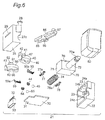
- the trigger switch 20 has a switching unit 21, a first switching member 90, and a second switching member 95.
- the switching unit 21 has first and second container halves, or first and second container halves 22 and 25, designed to be assembled with each other for forming a container which receives various components such as a printed circuit board 30, first and second crank members 40 and 60, a plunger 70, etc.
- the switching unit 21 further includes a trigger 80 and an actuating lever 85.
- the first container half 22 which is a box-like resin molding member, has a pair of opposed projecting ribs 23 integrally mounted on the opposing inner side surfaces thereof for receiving and positioning a printed circuit board 30 which will be described below.
- the first container half 22 also has a pair of semi-circular cutout 24a and 24b formed at an upper wall edge thereof and a semi-circular cutout 24c formed at one side wall edge thereof for receiving an operating shaft 72 of a plunger 70 which will be described below.
- the first container half 22 has a plurality of positioning dents 22a, 22b, 22c, 22d, 22e, and 22f integrally formed on an inner side surface which opposes the second container half 22 (described below) when the first and second container halves 22 and 25 are assembled with each other.
- the positioning dents 22a-22f are designed to provide click feeling to an operator of the power tool at the driving of the first or second crank member 40, 60.
- the second container half 25 which is a box-like resin molding member and defines an opening having an area which is substantially the same as that of the first container half 22, has a pair of opposed projecting ribs 26 integrally mounted on the opposing inner side surfaces thereof for receiving and positioning the printed circuit board 30 which will be described below.
- the second container half 25 also has a pair of semi-circular cutouts 27a and 27b and a shaft 28, both formed in an upper wall edge thereof.
- the second container half 25 has a semi-circular cutout 27c formed at one side wall edge thereof for receiving the operating shaft 72 of the plunger 70 which will be described below.
- the second container half 25 has a slot 29 formed in a side wall opposing the first container half 26 when the first and second container halves 22 and 25 are assembled with each other.
- the shaft 28 is illustrated in the drawings in such a manner that a top portion thereof is thermally deformed.
- the printed circuit board 30 has a projected portion 31 which is projected sideway from a peripheral edge portion thereof.
- the printed circuit board 30 supports two, arch-like wiring patterns which extend around respective centers on the board.
- One wiring patterns, which are provided to change a rotational direction of the chuck 14, are designed so that two contacts 51 and 52 of a first slider 50 slidingly move on and along the patterns.
- the wiring patterns have a common wiring pattern 34 and a pair of driving force reciprocally switching wiring patterns 35a and 35b positioned in a coaxial fashion with the common wiring pattern 34 for switching a rotational direction of the motor. As shown, the driving force reciprocally switching wiring patterns 35a and 35b are separated and positioned symmetrically with respect to neutral positions provided therebetween.
- the other wiring patterns which are provided to change a rotational force or torque of the chuck 14, are designed so that two contacts 56 and 57 of a second slider 55 slidingly move on and along the patterns.
- the wiring patterns have a common wiring pattern 36 and a driving force stepwisely switching wiring patterns 37b, 37a, and 37c positioned in a coaxial fashion with the common wiring pattern 36 for changing the rotational force in three levels, i.e., high, intermediate, and low levels.
- the driving force stepwisely switching wiring patterns 37b, 37a, and 37c for the high, intermediate, and low rotational force are positioned on a circle (not shown) at regular intervals
- the printed circuit board 30 supports an on/off wiring pattern and a resistance wiring pattern provided in parallel on a bottom surface thereof.
- the on/off wiring pattern is made of a pair of conducting materials printed and aligned spacedly on a line not shown.
- the resistance wiring pattern has a conducting material and a sliding resistance material printed and aligned spacedly on a line not shown.
- the sliding resistance of the resistance wiring pattern has conducting portions provided at opposite ends thereof.
- the projected portion 31 of the printed circuit board 30 supports a connector 33 having a number of terminals 32 aligned at regular intervals on the board for an electric connection with an external circuit not shown.
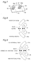
- the first crank member 40 which is provided to change the rotational direction of the chuck 14, has a first rotating shaft 41 projected from the upper surface thereof and a first actuator 42 extending sideway from the top portion of the first rotating shaft 41. Also, the first crank member 40 has an outer peripheral surface including a first hole 43 defined therein. The first hole 43 receives a first helical spring 44 and a first ball 45 in this order so that the first ball 45 moves in and out of the hole 43. The first ball 45 acts to provide click feeling to the operator. As shown in Fig. 6 , the first crank member 40 has a first step 46 formed in a bottom surface thereof for holding a first slider 50. The first step 46 has a first fit-in groove 47 formed at a corner thereof for holding a fit-in portion 50a of the first slider 50 (described below) fitted therein.
- the first slider 50 also has two contacts 51 and 52 extending in parallel to each other from the one-end raised fit-in portion 50a.
- the contacts 51 and 52 form a twin contact structure in order to obtain an increased contact reliablity of the slider.
- the second slider 55 has two contacts 56 and 57 extending in parallel to each other from the one-end bent fit-in portion 55a.
- the contacts 56 and 57 form a twin contact structure in order to obtain an increased contact reliablity of the slider.
- the second crank 60 which is provided to change the rotational force of the chuck 14 in three levels, i.e., high, intermediate, and low levels, has a second shaft 61 projected from the upper surface thereof and a second actuator 62 extending sideway from the top portion of the second shaft 61.
- the second crank member 60 has an outer peripheral surface including a second hole 63 defined therein.
- the second hole 63 receives a second helical spring 64 and a second ball 65 in this order so that the second ball 65 moves in and out of the hole 63 to provide click feeling to the operator.
- the second crank member 60 has a second step 66 formed in a bottom surface thereof for holding the second slider 55.
- the second step 66 has a second fit-in groove 67 formed at a corner thereof for holding a fit-in portion 55a of the second slider 55 (described below) fitted therein.
- the plunger 70 has a base 71.
- the base 71 has a pair of opposed side surfaces, one supporting the operating shaft 72 projecting therefrom and the other having a fit-in hole 73 defined therein and aligned in the same direction with the operating shaft 72.
- the operating shaft 72 has an engagement rib 72a formed at one end thereof.
- the fit-in hole 73 receives a helical spring 74.
- the base 71 also has a pair of fit-in grooves 75 and 76 formed on a top surface thereof.
- the fit-in grooves 75 and 76 are formed in parallel to the operating shaft 72.
- the fit-in grooves 75 and76 are designed to receive an on/off slider 77 and a resistance slider 78 which will be described below.
- the fit-in grooves 75 and 76 each has opposed fit-in recesses 75a and 76a formed at the respective centers of opposing inner side surfaces thereof.
- either end of the on/off slider 77 has a twin contact structure formed with a pair of spaced prongs. Also, the on/off slider 77 has a pair of elastic nails 77a formed at and raised from respective centers of longitudinal edges of the slider. The on/off sliders 77 are securely fitted in the fit-in groove 75 of the plunger 70 with the elastic nails 77a engaged in the recesses 75a.
- either end of the resistance slider 78 has a twin contact structure formed with a pair of spaced prongs. Also, the resistance slider 78 has a pair of elastic nails 78a formed at and raised from respective centers of longitudinal edges of the slider. The resistance sliders 78 are securely fitted in the fit-in groove 76 of the plunger 70 with the elastic nails 78a engaged in the recesses 76a.
- the trigger 80 is a mold member having a bracket-like cross section and has a reinforcement rib 81 extending between the opposed inner side surfaces.
- the rib 81 has a positioning boss 82 formed integrally at an upper central portion thereof. As shown in Fig. 12 , the trigger 80 is assembled with the plunger 70 with the engagement rib 72a of the plunger 70 engaged in an associated portion 83 formed on an opposing inner sider surface of the trigger 80.
- the actuating lever 85 has a shaft hole 86 formed at a central portion thereof, a projected portion 87 projected from one end thereof, and an engagement groove 88 formed at the other end thereof.
- the actuating lever 85 is supported for rotation with the shaft 28 of the second container half 25 inserted in the shaft hole 86.
- the first switching member 90 which is made of a rod-like member having an ellipse cross section, is assembled for sliding movement in the corresponding hole 15 (see Figs. 1 and 2 ) defined in the body housing 11.
- the first switching member 90 has a switching projection 91 projected from one side thereof.
- the switching portion 91 has an engagement recess 92 formed at a distal end thereof, in which the first actuator 42 of the first crank member 40 engages.
- the second switching member 95 which is made of a rod-like member having an ellipse cross section, is assembled for sliding movement in the corresponding hole 16 defined in the body housing 11.
- the second switching member 95 has a switching projection 96 projected from a bottom surface thereof.
- the switching portion 96 has an engagement hole 97 formed at a bottom surface thereof, in which the second actuator 62 of the first crank member 40 engages.
- the elastic nails 77a of the on/off slider 77 are fitted in the recesses 75a of the fit-in grooves 75 of the plunger 70.
- the elastic nails 78a of the resistance slider 78 are fitted in the recesses 76a of the fit-in groove 76 of the plunger 70.
- the helical spring 74 is inserted in the engagement hole 73 of the plunger 70.
- the first helical spring 44 and then the first ball 45 are assembled in the first hole 43 of the first crank member 40.
- the second helical spring 64 and then the second ball 65 are assembled in the second hole 63 of the second crank member 60.
- the fit-in portion 50a of the first slider 50 is fitted in the first fit-in groove 47 of the first crank member 40.
- the fit-in portion 55a of the second slider 55 is fitted in the second fit-in groove 67 of the second crank member 60.
- the printed circuit board 30 is positioned on the projecting ribs 26 of the second container half 25 with the projected portion 31 inserted through the slot 29.
- the first and second rotating shafts 41 and 61 of the first and second crank members 40 and 60 are fitted in the semi-circular cutouts 27a and 27b of the second container half 25, respectively.
- the operating shaft 72 of the plunger 70 is fitted in the semi-circular cutout 27c of the second container half 25.
- the first container half 22 is integrally assembled with the second container half 25. This results in an electric circuit shown in Fig. 17 .
- the first and second actuators 42 and 62 of the first and second crank members 40 and 60 are projected from the first and second container halves 22 and 25.
- the connector 33 is mounted on the projected portion 31 of the printed circuit board 30. Furthermore, the first actuator 42 of the first crank member 40 is fitted in the engagement groove 88 of the actuating lever 85.
- the shaft 28 of the second container half 25 is inserted in shaft hole 86 of the actuating lever 85, and then the projected upper end of the shaft 28 is thermally deformed as shown in the drawings. Then, the trigger 80 is integrated with the plunger 70 with the engagement rib 72a of the plunger 70 engaged in an associated portion 83 of the trigger 80.
- the first actuator 42 of the first crank member 40 is engaged with the fist engagement recess 92 of the first switching member 90.
- the second actuator 62 of the second crank member 60 is engaged with the second engagement hole 97 of the second switching member 95.
- the first and second switching members 90 and 95 are assembled in the corresponding holes 15, 16 of the power driver 10.
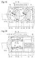
- the actuating lever 85 takes its neutral position with its projected portion 87 engaged in the engagement recess 92 of the first switching member 90.
- the positioning boss 82 of the trigger 80 positions on a central axis of the actuating lever 85, and the first slider 50 on the first crank member 40 takes its neutral position.
- the contact 51 of the first slider 50 is in contact with the common wiring pattern 34 and the contact 52 is out of contact with any wiring pattern.
- the trigger 80 is unable to be pulled in its longitudinal direction by the contact of the positioning boss 82 of the trigger 80 with the distal end portion of the actuating lever 85. This in turn prevents the plunger 70 from being moved in its longitudinal direction so that the on/off slider 77 and the resistance slider 78 on the base 71 are retained, without moving, on the lower surface of the printed circuit board 30.
- the contact 51 moves in contact with the common wiring pattern 34 and the contact 52 moves in contact with the driving force reciprocally switching wiring pattern 35a for rotations in the positive direction.
- the first ball 45 of the first crank member 40 moves out of the positioning dent 22b of the first container half 22 and then into the neighborhood positioning dent 22c (see Fig. 15 ), which provides click feeling to the operator.
- the second crank member 60 takes its neutral position with the second actuator 62 engaged in the engagement hole 97 of the second switching member 95.
- the contact 56 of the second slider 55 mounted in the second crank member 60 is in contact with the common wiring pattern 36, and the contact 57 is in contact with the driving force stepwisely switching wiring portion 37a for the intermediate rotational force. This causes that the second slider 55 is electrically connected to a circuit for generating the intermediate rotational force.
- the plunger 70 When the trigger 80 is pulled, the plunger 70 is slidingly forced inward along the central axis thereof against the force from the helical spring 74. This causes the on/off slider 77 and the resistance slider 78 on the base 71 of the plunger 70 to move in contact with the bottom surface of the printed circuit board 30. In this movement, the opposite ends of the resistant slider 78 are brought into contact with the associated resistant wiring pattern to make an electric connection therebetween. At this moment, neither end of the on/off slider 77 is out of contact with the associated on/off wiring pattern. This results in that no control signal is transmitted to the motor control circuit, so that the motor is in inoperative condition.
- the on/off slider 77 moves into contact with the associated on/off wiring pattern, supplying electric current to the control circuit.
- the resistance slider 78 moves with the inward movement of the trigger 80 to change the electric resistance. This in turn changes an electric signal to the control circuit depending upon the change of the electric resistance.
- the control circuit activates its FET transistor according to the electric signal to output an electric power to the motor. This causes the chuck 14 to rotate in the positive direction in a state capable of exerting the intermediate rotational force.
- the electric resistance increases with the inward movement of the trigger 80, which changes the control signal to increase and maximize the rotation number of the motor.
- the plunger 70 is forced back by the biasing force from the helical spring 74. This causes the on/off slider 77 and the resistance slider 78 to move backward, decreasing the electric resistance and, as a result, the rotation number of the motor. When the rotation of the motor is halted, the trigger 80 returns its original position.
- the first ball 45 of the first crank member 40 moves out of the positioning dent 22c of the first container half 22 through the positioning dent 22b (see Fig. 15 ) finally into the positioning dent 22a.
- the operator experiences two click feelings.
- the second crank member 60 rotates about the second rotating shaft 61 in a counterclockwise direction. This causes that the second slider 55 of the second crank member 60 moves from the driving force stepwisely switching wiring portion 37a for the intermediate rotational force to the driving force stepwisely switching wiring portion 37b for the high rotational force where it is electrically connected to the control circuit for the high rotational force. In this movement, the second ball 65 of the second crank member 60 moves out of the positioning dent 22e of the first container half 22 then into the positioning dent 22f, which provides click feeling to the operator.
- the plunger 70 moves in the longitudinal direction thereof and the on/off slider 77 and the resistance slider 78 move in contact with the bottom surface of the printed circuit board to output associated control signals, which allows the chuck 14 to rotate in the opposite direction in a state capable of exerting the high rotational force.
- the chuck 14 can be rotated in a state capable of exerting the low rotational force.
- Fig. 18 shows a second embodiment which is substantially the same as the first embodiment except that the second switching member 95 is inclined to the body housing 11.
- this embodiment increases an operability and decreases likelihood of erroneous operation of the power driver.
- the second switching member 95 has a projection 98 formed on opposite end surfaces thereof. This arrangement further avoids the likelihood of erroneous operation of the power driver.
- Like parts are designated by like reference numerals and no further discussion is made to those parts because they are substantially the same as those of the first embodiment.
- Fig. 19 shows a third embodiment which is substantially the same as the first embodiment except that either end of the second switching member 95 has a trapezoidal cross section. This arrangement further avoids the likelihood of erroneous operation of the power driver. Like parts are designated by like reference numerals and no further discussion is made to those parts because they are substantially the same as those of the first embodiment.
- Fig. 20 shows a fourth embodiment which is substantially the same as the first embodiment except that the second switching member 95 is inclined to the body housing 11 and either end of the second switching member 95 has a trapezoidal cross section.
- this embodiment increases an operability and decreases likelihood of erroneous operation of the power driver.
- the second switching member 95 has a projection 98 formed on opposite end surfaces thereof. This arrangement further avoids the likelihood of erroneous operation of the power driver.
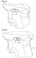
- Fig. 21 shows a fifth embodiment which is substantially the same as the first embodiment except that the first and second switching members 90 and 95 are positioned side-by-side. According to this arrangement, the operator can operate the switch with minimum finger movements, which increases the operability of the power driver. Another exception is that the longitudinal ends of the first switching member 90 are shifted in that direction from those of the second switching member 95 to form height differences therebetween, which ensures to avoid the likelihood of erroneous operation of the power driver.
- Fig. 22 shows a sixth embodiment which is substantially the same as the fifth embodiment except that the second switching member 95 has a projection 98 formed on opposite end surfaces thereof. This arrangement further avoids the likelihood of erroneous operation of the power driver.
- the rotational force is changed in three levels in the previous embodiments, it may be changed in two levels, i.e., high and low rotational forces, or in four or five levels.
- the switch according to the invention may be used for changing operational conditions thereof as well as changing rotational direction or force of the power tool.
- the invention may be applied to various switches for changing other control circuits.
- the invention may be applied to other power tools such as impact driver and power saw.
- the invention is not limited to the power tool with the switch described above and can be applied to other power tools in which the first and second switching members are provided at respective positions where the operator can access with his or her fingers while holding the grip or handle of the body housing by one hand.
- the invention may have three or more switching members.
Landscapes
- Engineering & Computer Science (AREA)
- Mechanical Engineering (AREA)
- Push-Button Switches (AREA)
- Switch Cases, Indication, And Locking (AREA)
- Portable Power Tools In General (AREA)
- Tumbler Switches (AREA)
- Contacts (AREA)
- Rotary Switch, Piano Key Switch, And Lever Switch (AREA)
- Slide Switches (AREA)
Applications Claiming Priority (1)
| Application Number | Priority Date | Filing Date | Title |
|---|---|---|---|
| JP2015110560A JP2016225147A (ja) | 2015-05-29 | 2015-05-29 | スイッチ |
Publications (3)
| Publication Number | Publication Date |
|---|---|
| EP3101670A2 true EP3101670A2 (fr) | 2016-12-07 |
| EP3101670A3 EP3101670A3 (fr) | 2017-03-08 |
| EP3101670B1 EP3101670B1 (fr) | 2020-02-12 |
Family
ID=55967040
Family Applications (1)
| Application Number | Title | Priority Date | Filing Date |
|---|---|---|---|
| EP16167066.6A Active EP3101670B1 (fr) | 2015-05-29 | 2016-04-26 | Interrupteur pour outil motorisé |
Country Status (4)
| Country | Link |
|---|---|
| US (1) | US9812267B2 (fr) |
| EP (1) | EP3101670B1 (fr) |
| JP (1) | JP2016225147A (fr) |
| CN (1) | CN106206096B (fr) |
Cited By (1)
| Publication number | Priority date | Publication date | Assignee | Title |
|---|---|---|---|---|
| WO2020239600A1 (fr) * | 2019-05-28 | 2020-12-03 | Festool Gmbh | Commutateur pour une machine-outil manuelle |
Families Citing this family (5)
| Publication number | Priority date | Publication date | Assignee | Title |
|---|---|---|---|---|
| CN109661310B (zh) * | 2016-09-08 | 2021-11-19 | 惠普发展公司,有限责任合伙企业 | 介质尺寸检测器 |
| US11534903B2 (en) | 2017-08-28 | 2022-12-27 | Apex Brands, Inc. | Power tool two-stage trigger |
| JP7095251B2 (ja) * | 2017-09-29 | 2022-07-05 | マックス株式会社 | 工具 |
| JP7135589B2 (ja) | 2018-08-24 | 2022-09-13 | オムロン株式会社 | トリガスイッチ |
| JP2026005782A (ja) * | 2024-06-27 | 2026-01-16 | オムロン株式会社 | トリガスイッチおよびこれを備えた電動工具、トリガスイッチの制御方法、制御プログラム |
Citations (1)
| Publication number | Priority date | Publication date | Assignee | Title |
|---|---|---|---|---|
| JP2011067910A (ja) | 2009-09-25 | 2011-04-07 | Toku Hanbai Kk | 自動車タイヤ交換用のホイールナットの締付け工具 |
Family Cites Families (7)
| Publication number | Priority date | Publication date | Assignee | Title |
|---|---|---|---|---|
| US4313041A (en) * | 1978-12-25 | 1982-01-26 | Shigeo Ohashi | Small switch |
| US5570777A (en) * | 1995-08-04 | 1996-11-05 | Paragon Electric Company, Inc. | Circuit board mounted switch assembly |
| US7594549B2 (en) * | 2007-04-15 | 2009-09-29 | Basso Industry Corp. | Rotating direction switching device for a pneumatic tool |
| JP5262701B2 (ja) * | 2008-12-26 | 2013-08-14 | オムロン株式会社 | 電動工具用スイッチ |
| JP5405240B2 (ja) * | 2009-09-04 | 2014-02-05 | 株式会社マキタ | 電動工具におけるレバーの防水構造 |
| JP5760957B2 (ja) * | 2011-11-02 | 2015-08-12 | マックス株式会社 | 回転工具 |
| JP6160303B2 (ja) * | 2013-06-27 | 2017-07-12 | オムロン株式会社 | スイッチユニット |
-
2015
- 2015-05-29 JP JP2015110560A patent/JP2016225147A/ja active Pending
-
2016
- 2016-04-26 EP EP16167066.6A patent/EP3101670B1/fr active Active
- 2016-04-27 CN CN201610269223.7A patent/CN106206096B/zh active Active
- 2016-04-29 US US15/142,681 patent/US9812267B2/en active Active
Patent Citations (1)
| Publication number | Priority date | Publication date | Assignee | Title |
|---|---|---|---|---|
| JP2011067910A (ja) | 2009-09-25 | 2011-04-07 | Toku Hanbai Kk | 自動車タイヤ交換用のホイールナットの締付け工具 |
Cited By (4)
| Publication number | Priority date | Publication date | Assignee | Title |
|---|---|---|---|---|
| WO2020239600A1 (fr) * | 2019-05-28 | 2020-12-03 | Festool Gmbh | Commutateur pour une machine-outil manuelle |
| CN114175199A (zh) * | 2019-05-28 | 2022-03-11 | 费斯托工具有限责任公司 | 用于手持式工具机器的切换件 |
| US12288654B2 (en) | 2019-05-28 | 2025-04-29 | Festool Gmbh | Switch for a hand-held power tool |
| CN114175199B (zh) * | 2019-05-28 | 2025-07-15 | 费斯托工具有限责任公司 | 用于手持式工具机器的切换件 |
Also Published As
| Publication number | Publication date |
|---|---|
| CN106206096B (zh) | 2019-02-15 |
| EP3101670B1 (fr) | 2020-02-12 |
| CN106206096A (zh) | 2016-12-07 |
| US20160351355A1 (en) | 2016-12-01 |
| US9812267B2 (en) | 2017-11-07 |
| EP3101670A3 (fr) | 2017-03-08 |
| JP2016225147A (ja) | 2016-12-28 |
Similar Documents
| Publication | Publication Date | Title |
|---|---|---|
| EP3101670B1 (fr) | Interrupteur pour outil motorisé | |
| JP5813725B2 (ja) | スイッチ装置 | |
| US20210060418A1 (en) | Manipulation input device | |
| US6903293B2 (en) | Switch device having good sense of operational touch even when sliding operating knob or rocking operating knob is attached thereto | |
| CN102341219B (zh) | 电动工具 | |
| JP5555015B2 (ja) | 車載用入力装置 | |
| US10770245B2 (en) | Contact structure for switch, trigger switch and electric power tool | |
| US6841750B2 (en) | Switch device | |
| EP2639803B1 (fr) | Dispositif de commutation de direction | |
| JP3921909B2 (ja) | レバースイッチ及びこれを用いた複合スイッチ | |
| JP3875530B2 (ja) | スイッチ操作機構 | |
| KR101423145B1 (ko) | 복합 조작형 스위치 장치 | |
| CN103978465B (zh) | 手持式工具机 | |
| JP2007157402A (ja) | トリガースイッチ | |
| JP5351555B2 (ja) | 電動工具のスイッチ | |
| CN215731572U (zh) | 一种多功能组合开关手柄总成结构 | |
| JP5867201B2 (ja) | スイッチ | |
| EP3214632B1 (fr) | Dispositif d'entrée multidirectionnelle | |
| JP2022117449A (ja) | 電気スイッチ装置 | |
| JP5613526B2 (ja) | 電池ボックス | |
| US6844510B2 (en) | Stalk switch | |
| US4812603A (en) | Dimmer switch | |
| CN223314956U (zh) | 一种组合开关手柄以及车用组合开关 | |
| CN209029282U (zh) | 一种按键结构 | |
| JP2003045287A (ja) | 車載用スイッチ装置 |
Legal Events
| Date | Code | Title | Description |
|---|---|---|---|
| PUAI | Public reference made under article 153(3) epc to a published international application that has entered the european phase |
Free format text: ORIGINAL CODE: 0009012 |
|
| STAA | Information on the status of an ep patent application or granted ep patent |
Free format text: STATUS: REQUEST FOR EXAMINATION WAS MADE |
|
| 17P | Request for examination filed |
Effective date: 20160519 |
|
| AK | Designated contracting states |
Kind code of ref document: A2 Designated state(s): AL AT BE BG CH CY CZ DE DK EE ES FI FR GB GR HR HU IE IS IT LI LT LU LV MC MK MT NL NO PL PT RO RS SE SI SK SM TR |
|
| AX | Request for extension of the european patent |
Extension state: BA ME |
|
| PUAL | Search report despatched |
Free format text: ORIGINAL CODE: 0009013 |
|
| AK | Designated contracting states |
Kind code of ref document: A3 Designated state(s): AL AT BE BG CH CY CZ DE DK EE ES FI FR GB GR HR HU IE IS IT LI LT LU LV MC MK MT NL NO PL PT RO RS SE SI SK SM TR |
|
| AX | Request for extension of the european patent |
Extension state: BA ME |
|
| RIC1 | Information provided on ipc code assigned before grant |
Ipc: H01H 19/58 20060101ALI20170131BHEP Ipc: H01H 9/06 20060101AFI20170131BHEP |
|
| STAA | Information on the status of an ep patent application or granted ep patent |
Free format text: STATUS: EXAMINATION IS IN PROGRESS |
|
| 17Q | First examination report despatched |
Effective date: 20181221 |
|
| GRAP | Despatch of communication of intention to grant a patent |
Free format text: ORIGINAL CODE: EPIDOSNIGR1 |
|
| STAA | Information on the status of an ep patent application or granted ep patent |
Free format text: STATUS: GRANT OF PATENT IS INTENDED |
|
| INTG | Intention to grant announced |
Effective date: 20190919 |
|
| GRAS | Grant fee paid |
Free format text: ORIGINAL CODE: EPIDOSNIGR3 |
|
| GRAA | (expected) grant |
Free format text: ORIGINAL CODE: 0009210 |
|
| STAA | Information on the status of an ep patent application or granted ep patent |
Free format text: STATUS: THE PATENT HAS BEEN GRANTED |
|
| AK | Designated contracting states |
Kind code of ref document: B1 Designated state(s): AL AT BE BG CH CY CZ DE DK EE ES FI FR GB GR HR HU IE IS IT LI LT LU LV MC MK MT NL NO PL PT RO RS SE SI SK SM TR |
|
| REG | Reference to a national code |
Ref country code: GB Ref legal event code: FG4D |
|
| REG | Reference to a national code |
Ref country code: CH Ref legal event code: EP |
|
| REG | Reference to a national code |
Ref country code: AT Ref legal event code: REF Ref document number: 1233206 Country of ref document: AT Kind code of ref document: T Effective date: 20200215 |
|
| REG | Reference to a national code |
Ref country code: DE Ref legal event code: R096 Ref document number: 602016029353 Country of ref document: DE |
|
| REG | Reference to a national code |
Ref country code: IE Ref legal event code: FG4D |
|
| PG25 | Lapsed in a contracting state [announced via postgrant information from national office to epo] |
Ref country code: NO Free format text: LAPSE BECAUSE OF FAILURE TO SUBMIT A TRANSLATION OF THE DESCRIPTION OR TO PAY THE FEE WITHIN THE PRESCRIBED TIME-LIMIT Effective date: 20200512 Ref country code: FI Free format text: LAPSE BECAUSE OF FAILURE TO SUBMIT A TRANSLATION OF THE DESCRIPTION OR TO PAY THE FEE WITHIN THE PRESCRIBED TIME-LIMIT Effective date: 20200212 Ref country code: RS Free format text: LAPSE BECAUSE OF FAILURE TO SUBMIT A TRANSLATION OF THE DESCRIPTION OR TO PAY THE FEE WITHIN THE PRESCRIBED TIME-LIMIT Effective date: 20200212 |
|
| REG | Reference to a national code |
Ref country code: LT Ref legal event code: MG4D |
|
| REG | Reference to a national code |
Ref country code: NL Ref legal event code: MP Effective date: 20200212 |
|
| PG25 | Lapsed in a contracting state [announced via postgrant information from national office to epo] |
Ref country code: IS Free format text: LAPSE BECAUSE OF FAILURE TO SUBMIT A TRANSLATION OF THE DESCRIPTION OR TO PAY THE FEE WITHIN THE PRESCRIBED TIME-LIMIT Effective date: 20200612 Ref country code: LV Free format text: LAPSE BECAUSE OF FAILURE TO SUBMIT A TRANSLATION OF THE DESCRIPTION OR TO PAY THE FEE WITHIN THE PRESCRIBED TIME-LIMIT Effective date: 20200212 Ref country code: SE Free format text: LAPSE BECAUSE OF FAILURE TO SUBMIT A TRANSLATION OF THE DESCRIPTION OR TO PAY THE FEE WITHIN THE PRESCRIBED TIME-LIMIT Effective date: 20200212 Ref country code: GR Free format text: LAPSE BECAUSE OF FAILURE TO SUBMIT A TRANSLATION OF THE DESCRIPTION OR TO PAY THE FEE WITHIN THE PRESCRIBED TIME-LIMIT Effective date: 20200513 Ref country code: HR Free format text: LAPSE BECAUSE OF FAILURE TO SUBMIT A TRANSLATION OF THE DESCRIPTION OR TO PAY THE FEE WITHIN THE PRESCRIBED TIME-LIMIT Effective date: 20200212 Ref country code: BG Free format text: LAPSE BECAUSE OF FAILURE TO SUBMIT A TRANSLATION OF THE DESCRIPTION OR TO PAY THE FEE WITHIN THE PRESCRIBED TIME-LIMIT Effective date: 20200512 |
|
| PG25 | Lapsed in a contracting state [announced via postgrant information from national office to epo] |
Ref country code: NL Free format text: LAPSE BECAUSE OF FAILURE TO SUBMIT A TRANSLATION OF THE DESCRIPTION OR TO PAY THE FEE WITHIN THE PRESCRIBED TIME-LIMIT Effective date: 20200212 |
|
| PG25 | Lapsed in a contracting state [announced via postgrant information from national office to epo] |
Ref country code: DK Free format text: LAPSE BECAUSE OF FAILURE TO SUBMIT A TRANSLATION OF THE DESCRIPTION OR TO PAY THE FEE WITHIN THE PRESCRIBED TIME-LIMIT Effective date: 20200212 Ref country code: SM Free format text: LAPSE BECAUSE OF FAILURE TO SUBMIT A TRANSLATION OF THE DESCRIPTION OR TO PAY THE FEE WITHIN THE PRESCRIBED TIME-LIMIT Effective date: 20200212 Ref country code: EE Free format text: LAPSE BECAUSE OF FAILURE TO SUBMIT A TRANSLATION OF THE DESCRIPTION OR TO PAY THE FEE WITHIN THE PRESCRIBED TIME-LIMIT Effective date: 20200212 Ref country code: PT Free format text: LAPSE BECAUSE OF FAILURE TO SUBMIT A TRANSLATION OF THE DESCRIPTION OR TO PAY THE FEE WITHIN THE PRESCRIBED TIME-LIMIT Effective date: 20200705 Ref country code: LT Free format text: LAPSE BECAUSE OF FAILURE TO SUBMIT A TRANSLATION OF THE DESCRIPTION OR TO PAY THE FEE WITHIN THE PRESCRIBED TIME-LIMIT Effective date: 20200212 Ref country code: ES Free format text: LAPSE BECAUSE OF FAILURE TO SUBMIT A TRANSLATION OF THE DESCRIPTION OR TO PAY THE FEE WITHIN THE PRESCRIBED TIME-LIMIT Effective date: 20200212 Ref country code: CZ Free format text: LAPSE BECAUSE OF FAILURE TO SUBMIT A TRANSLATION OF THE DESCRIPTION OR TO PAY THE FEE WITHIN THE PRESCRIBED TIME-LIMIT Effective date: 20200212 Ref country code: RO Free format text: LAPSE BECAUSE OF FAILURE TO SUBMIT A TRANSLATION OF THE DESCRIPTION OR TO PAY THE FEE WITHIN THE PRESCRIBED TIME-LIMIT Effective date: 20200212 Ref country code: SK Free format text: LAPSE BECAUSE OF FAILURE TO SUBMIT A TRANSLATION OF THE DESCRIPTION OR TO PAY THE FEE WITHIN THE PRESCRIBED TIME-LIMIT Effective date: 20200212 |
|
| REG | Reference to a national code |
Ref country code: DE Ref legal event code: R097 Ref document number: 602016029353 Country of ref document: DE |
|
| REG | Reference to a national code |
Ref country code: AT Ref legal event code: MK05 Ref document number: 1233206 Country of ref document: AT Kind code of ref document: T Effective date: 20200212 |
|
| PG25 | Lapsed in a contracting state [announced via postgrant information from national office to epo] |
Ref country code: MC Free format text: LAPSE BECAUSE OF FAILURE TO SUBMIT A TRANSLATION OF THE DESCRIPTION OR TO PAY THE FEE WITHIN THE PRESCRIBED TIME-LIMIT Effective date: 20200212 |
|
| REG | Reference to a national code |
Ref country code: CH Ref legal event code: PL |
|
| PLBE | No opposition filed within time limit |
Free format text: ORIGINAL CODE: 0009261 |
|
| STAA | Information on the status of an ep patent application or granted ep patent |
Free format text: STATUS: NO OPPOSITION FILED WITHIN TIME LIMIT |
|
| 26N | No opposition filed |
Effective date: 20201113 |
|
| PG25 | Lapsed in a contracting state [announced via postgrant information from national office to epo] |
Ref country code: CH Free format text: LAPSE BECAUSE OF NON-PAYMENT OF DUE FEES Effective date: 20200430 Ref country code: LU Free format text: LAPSE BECAUSE OF NON-PAYMENT OF DUE FEES Effective date: 20200426 Ref country code: AT Free format text: LAPSE BECAUSE OF FAILURE TO SUBMIT A TRANSLATION OF THE DESCRIPTION OR TO PAY THE FEE WITHIN THE PRESCRIBED TIME-LIMIT Effective date: 20200212 Ref country code: LI Free format text: LAPSE BECAUSE OF NON-PAYMENT OF DUE FEES Effective date: 20200430 Ref country code: FR Free format text: LAPSE BECAUSE OF NON-PAYMENT OF DUE FEES Effective date: 20200430 Ref country code: IT Free format text: LAPSE BECAUSE OF FAILURE TO SUBMIT A TRANSLATION OF THE DESCRIPTION OR TO PAY THE FEE WITHIN THE PRESCRIBED TIME-LIMIT Effective date: 20200212 |
|
| REG | Reference to a national code |
Ref country code: BE Ref legal event code: MM Effective date: 20200430 |
|
| PG25 | Lapsed in a contracting state [announced via postgrant information from national office to epo] |
Ref country code: SI Free format text: LAPSE BECAUSE OF FAILURE TO SUBMIT A TRANSLATION OF THE DESCRIPTION OR TO PAY THE FEE WITHIN THE PRESCRIBED TIME-LIMIT Effective date: 20200212 Ref country code: BE Free format text: LAPSE BECAUSE OF NON-PAYMENT OF DUE FEES Effective date: 20200430 Ref country code: PL Free format text: LAPSE BECAUSE OF FAILURE TO SUBMIT A TRANSLATION OF THE DESCRIPTION OR TO PAY THE FEE WITHIN THE PRESCRIBED TIME-LIMIT Effective date: 20200212 |
|
| GBPC | Gb: european patent ceased through non-payment of renewal fee |
Effective date: 20200512 |
|
| PG25 | Lapsed in a contracting state [announced via postgrant information from national office to epo] |
Ref country code: IE Free format text: LAPSE BECAUSE OF NON-PAYMENT OF DUE FEES Effective date: 20200426 Ref country code: GB Free format text: LAPSE BECAUSE OF NON-PAYMENT OF DUE FEES Effective date: 20200512 |
|
| PG25 | Lapsed in a contracting state [announced via postgrant information from national office to epo] |
Ref country code: TR Free format text: LAPSE BECAUSE OF FAILURE TO SUBMIT A TRANSLATION OF THE DESCRIPTION OR TO PAY THE FEE WITHIN THE PRESCRIBED TIME-LIMIT Effective date: 20200212 Ref country code: MT Free format text: LAPSE BECAUSE OF FAILURE TO SUBMIT A TRANSLATION OF THE DESCRIPTION OR TO PAY THE FEE WITHIN THE PRESCRIBED TIME-LIMIT Effective date: 20200212 Ref country code: CY Free format text: LAPSE BECAUSE OF FAILURE TO SUBMIT A TRANSLATION OF THE DESCRIPTION OR TO PAY THE FEE WITHIN THE PRESCRIBED TIME-LIMIT Effective date: 20200212 |
|
| PG25 | Lapsed in a contracting state [announced via postgrant information from national office to epo] |
Ref country code: MK Free format text: LAPSE BECAUSE OF FAILURE TO SUBMIT A TRANSLATION OF THE DESCRIPTION OR TO PAY THE FEE WITHIN THE PRESCRIBED TIME-LIMIT Effective date: 20200212 Ref country code: AL Free format text: LAPSE BECAUSE OF FAILURE TO SUBMIT A TRANSLATION OF THE DESCRIPTION OR TO PAY THE FEE WITHIN THE PRESCRIBED TIME-LIMIT Effective date: 20200212 |
|
| PGFP | Annual fee paid to national office [announced via postgrant information from national office to epo] |
Ref country code: DE Payment date: 20250417 Year of fee payment: 10 |