EP3101757A1 - Terminal et dispositif de commande de charge de batterie et procédé associé - Google Patents
Terminal et dispositif de commande de charge de batterie et procédé associé Download PDFInfo
- Publication number
- EP3101757A1 EP3101757A1 EP14881017.9A EP14881017A EP3101757A1 EP 3101757 A1 EP3101757 A1 EP 3101757A1 EP 14881017 A EP14881017 A EP 14881017A EP 3101757 A1 EP3101757 A1 EP 3101757A1
- Authority
- EP
- European Patent Office
- Prior art keywords
- charging
- battery
- terminal
- main control
- control module
- Prior art date
- Legal status (The legal status is an assumption and is not a legal conclusion. Google has not performed a legal analysis and makes no representation as to the accuracy of the status listed.)
- Granted
Links
Images


Classifications
-
- H—ELECTRICITY
- H02—GENERATION; CONVERSION OR DISTRIBUTION OF ELECTRIC POWER
- H02J—ELECTRIC POWER NETWORKS; CIRCUIT ARRANGEMENTS OR SYSTEMS FOR SUPPLYING OR DISTRIBUTING ELECTRIC POWER; SYSTEMS FOR STORING ELECTRIC ENERGY
- H02J7/00—Circuit arrangements for charging or discharging batteries or for supplying loads from batteries
- H02J7/60—Circuit arrangements for charging or discharging batteries or for supplying loads from batteries including safety or protection arrangements
- H02J7/64—Circuit arrangements for charging or discharging batteries or for supplying loads from batteries including safety or protection arrangements against overvoltage
-
- H—ELECTRICITY
- H01—ELECTRIC ELEMENTS
- H01M—PROCESSES OR MEANS, e.g. BATTERIES, FOR THE DIRECT CONVERSION OF CHEMICAL ENERGY INTO ELECTRICAL ENERGY
- H01M10/00—Secondary cells; Manufacture thereof
- H01M10/42—Methods or arrangements for servicing or maintenance of secondary cells or secondary half-cells
- H01M10/44—Methods for charging or discharging
-
- H—ELECTRICITY
- H02—GENERATION; CONVERSION OR DISTRIBUTION OF ELECTRIC POWER
- H02J—ELECTRIC POWER NETWORKS; CIRCUIT ARRANGEMENTS OR SYSTEMS FOR SUPPLYING OR DISTRIBUTING ELECTRIC POWER; SYSTEMS FOR STORING ELECTRIC ENERGY
- H02J7/00—Circuit arrangements for charging or discharging batteries or for supplying loads from batteries
- H02J7/60—Circuit arrangements for charging or discharging batteries or for supplying loads from batteries including safety or protection arrangements
- H02J7/663—Circuit arrangements for charging or discharging batteries or for supplying loads from batteries including safety or protection arrangements using battery or load disconnect circuits
-
- H—ELECTRICITY
- H02—GENERATION; CONVERSION OR DISTRIBUTION OF ELECTRIC POWER
- H02J—ELECTRIC POWER NETWORKS; CIRCUIT ARRANGEMENTS OR SYSTEMS FOR SUPPLYING OR DISTRIBUTING ELECTRIC POWER; SYSTEMS FOR STORING ELECTRIC ENERGY
- H02J7/00—Circuit arrangements for charging or discharging batteries or for supplying loads from batteries
- H02J7/40—Circuit arrangements for charging or discharging batteries or for supplying loads from batteries characterised by the exchange of charge or discharge related data
- H02J7/42—Circuit arrangements for charging or discharging batteries or for supplying loads from batteries characterised by the exchange of charge or discharge related data with electronic devices having internal batteries, e.g. mobile phones
-
- H—ELECTRICITY
- H02—GENERATION; CONVERSION OR DISTRIBUTION OF ELECTRIC POWER
- H02J—ELECTRIC POWER NETWORKS; CIRCUIT ARRANGEMENTS OR SYSTEMS FOR SUPPLYING OR DISTRIBUTING ELECTRIC POWER; SYSTEMS FOR STORING ELECTRIC ENERGY
- H02J7/00—Circuit arrangements for charging or discharging batteries or for supplying loads from batteries
- H02J7/60—Circuit arrangements for charging or discharging batteries or for supplying loads from batteries including safety or protection arrangements
- H02J7/61—Circuit arrangements for charging or discharging batteries or for supplying loads from batteries including safety or protection arrangements against overcharge
-
- H—ELECTRICITY
- H02—GENERATION; CONVERSION OR DISTRIBUTION OF ELECTRIC POWER
- H02J—ELECTRIC POWER NETWORKS; CIRCUIT ARRANGEMENTS OR SYSTEMS FOR SUPPLYING OR DISTRIBUTING ELECTRIC POWER; SYSTEMS FOR STORING ELECTRIC ENERGY
- H02J7/00—Circuit arrangements for charging or discharging batteries or for supplying loads from batteries
- H02J7/60—Circuit arrangements for charging or discharging batteries or for supplying loads from batteries including safety or protection arrangements
- H02J7/62—Circuit arrangements for charging or discharging batteries or for supplying loads from batteries including safety or protection arrangements against overcurrent
-
- Y—GENERAL TAGGING OF NEW TECHNOLOGICAL DEVELOPMENTS; GENERAL TAGGING OF CROSS-SECTIONAL TECHNOLOGIES SPANNING OVER SEVERAL SECTIONS OF THE IPC; TECHNICAL SUBJECTS COVERED BY FORMER USPC CROSS-REFERENCE ART COLLECTIONS [XRACs] AND DIGESTS
- Y02—TECHNOLOGIES OR APPLICATIONS FOR MITIGATION OR ADAPTATION AGAINST CLIMATE CHANGE
- Y02E—REDUCTION OF GREENHOUSE GAS [GHG] EMISSIONS, RELATED TO ENERGY GENERATION, TRANSMISSION OR DISTRIBUTION
- Y02E60/00—Enabling technologies; Technologies with a potential or indirect contribution to GHG emissions mitigation
- Y02E60/10—Energy storage using batteries
Definitions
- the present disclosure generally relates to the charging technical field, and more particularly, to a terminal and a battery charging control device and method.
- a battery of a terminal is typically charged by connecting a communication interface of the terminal with an external power adapter.
- the charging current may be enhanced for performing a quick charging on the battery.
- the battery is charged in a conventional constant voltage mode or with increased charging current, if a charging current and/or charging voltage for the battery is too high during the charging, the battery will be damaged due to overvoltage and/or overcurrent charging. Therefore, in the related art, an overcurrent protection and/or an overvoltage protection cannot be realized for the battery during performing a regular charging or quick charging on the battery of the terminal.
- An objective of the present disclosure is to provide a battery charging control device, and to solve a problem in the related art that an overcurrent protection and/or an overvoltage protection cannot be realized for a battery during performing a regular charging or quick charging on the battery of a terminal.
- the present disclosure is realized as follows. There is provided a battery charging control device coupled with a battery and a controller in a terminal, in which the battery is charged by obtaining direct current from an external power adapter via a communication interface of the terminal, and the controller controls the communication interface of the terminal to switch on or off.
- the battery charging control device includes a battery connector, a main control module and a quick charging switch module.
- the battery connector is coupled with an electrode of the battery
- the main control module is coupled with the battery connector
- a first switch control terminal and a second switch control terminal of the main control module are coupled with a first controlled terminal and a second controlled terminal of the quick charging switch module respectively
- both a first communication terminal and a second communication terminal of the main control module are coupled with the communication interface
- the main control module is also coupled with the controller
- an input terminal of the quick charging switch module is coupled with a power wire of the communication interface
- an output terminal of the quick charging switch module is coupled with the battery connector.
- the main control module controls the quick charging switch module to switch off; when a quick charging is performed on the battery, the main control module controls the quick charging switch module to switch on, and direct current is introduced into the quick charging switch module via the communication interface, so as to charge the battery via the battery connector.
- the main control module performs a data communication with the external power adapter via the communication interface, and obtains a charging voltage and a charging current for the battery; if the charging voltage is greater than a voltage threshold and/or the charging current is greater than a current threshold, the main control module sends a charging switch-off instruction, such that the controller controls the communication interface to switch off; if the charging voltage is less than or equal to the voltage threshold and the charging current is less than or equal to the current threshold, the main control module continues to obtain the charging voltage and the charging current.
- Another objective of the present disclosure is to provide a terminal, including a communication interface, a controller, a battery and a battery charging control device described above.
- the battery charging control method includes can include following:
- the battery charging control device including the battery connector, the main control module and the quick charging switch module is adopted.
- the main control module performs a data communication with the external power adapter via the communication interface of the terminal, obtains the charging voltage and the charging current for the battery, and sends the charging switch-off instruction if the charging voltage is greater than the voltage threshold and/or the charging current is greater than the current threshold, such that the controller of the terminal controls the communication interface of the terminal to switch off, thus realizing the overvoltage protection and/or the overcurrent protection for the battery.
- Fig. 1 illustrates a block diagram of a battery charging control device according to an embodiment of the present disclosure. For illustration purposes, only parts related to embodiments of the present disclosure are shown, which will be described in detail in the following.
- the battery charging control device 100 provided in embodiments of the present disclosure is coupled with a battery 200 and a controller 300 in a terminal respectively.
- the battery 200 is charged by obtaining direct current from an external power adapter 400 via a communication interface 10 of the terminal.
- the controller 300 controls the communication interface 10 of the terminal to switch on or off.
- the battery charging control device 100 includes a battery connector 101, a main control module 102 and a quick charging switch module 103.
- the battery connector 101 is coupled with an electrode of the battery 200.
- the main control module 102 is coupled with the battery connector 101.
- a first switch control terminal and a second switch control terminal of the main control module 102 are coupled with a first controlled terminal and a second controlled terminal of the quick charging switch module 103 respectively.
- Both a first communication terminal and a second communication terminal of the main control module 102 are coupled with the communication interface 10 of the terminal.
- the main control module 102 is also coupled with the controller 300 of the terminal.
- An input terminal of the quick charging switch module 103 is coupled with a power wire VBUS of the communication interface 10 of the terminal, and an output terminal of the quick charging switch module 103 is coupled with the battery connector 101.
- the main control module 102 controls the quick charging switch module 103 to switch off.
- the main control module 102 controls the quick charging switch module 103 to switch on, and direct current is introduced into the quick charging switch module 103 via the communication interface 10 of the terminal for charging the battery 200 via the battery connector 101, such that the charging current for the battery 200 is increased, and thus quick charging is realized.
- the main control module 102 performs a data communication with the power adapter 400 via the communication interface 10 of the terminal, and obtains a charging voltage and a charging current for the battery 200. If the above charging voltage is greater than a voltage threshold and/or the above charging current is greater than a current threshold, the main control module 102 sends a charging switch-off instruction, such that the controller 300 controls the communication interface 10 of the terminal to switch off. If the above charging voltage is less than or equal to the voltage threshold and the above charging current is less than or equal to the current threshold, the main control module 102 continues to obtain the charging voltage and the charging current.
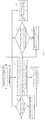
- embodiments of the present disclosure may further provide a battery charging control method.
- the battery charging control method includes following acts.
- the main control module 102 performs a data communication with the external power adapter 400, and obtains the charging current and the charging voltage for the battery 200.
- the main control module 102 determines whether the charging voltage is greater than the voltage threshold, and determines whether the charging current is greater than the current threshold. If the charging voltage is greater than the voltage threshold and/or the charging current is greater than the current threshold, block S3 is executed. If the charging voltage is less than or equal to the voltage threshold and the charging current is less than or equal to the current threshold, block S1 is returned to.
- the main control module 102 sends a charging switch-off instruction, such that the controller 300 controls the communication interface 10 of the terminal to switch off.
- block S1 specifically includes following acts.
- the main control module 102 sends a charging parameter obtaining request to the power adapter 400.
- the power adapter 400 feeds back charging voltage information and charging current information to the main control module 102 according to the charging parameter obtaining request.
- the main control module 102 obtains the charging current and the charging voltage for the battery 200 from the above charging current information and charging voltage information.
- block S4 the main control module 102 determines whether the charging voltage for the battery 200 is zero, if yes, block S5 is executed, and if no, block S1 is returned to.
- block S5 the main control module 102 controls the quick charging switch module 103 to switch off, and block S3 is executed.
- the controller 300 may feedback a quick charging switch-off instruction to the main control module 102 at an abnormal battery temperature if the terminal has a function of detecting a temperature of the battery, such that the main control module 102 may control the quick charging switch module 103 to switch off according to the quick charging switch-off instruction.
- the main control module 102 detects the voltage of the battery 200 via the battery connector 101, and determines whether the voltage of the battery 200 is greater than the quick charging voltage threshold (e.g. 4.35V), if yes, block S7 is executed, and if no, block S2 is executed.
- the quick charging voltage threshold e.g. 4.35V
- block S7 the main control module 102 controls the quick charging switch module 103 to switch off, and then block S2 is executed.
- the main control module 102 may also detect the electric quantity of the battery 200 via the battery connector 101, and feedback the electric quantity information to the controller 300 of the terminal, such that the terminal displays the electric quantity of the battery 200.
- the battery charging control method may further include following acts executed simultaneously with block S6.
- the main control module 102 detects the electric quantity of the battery 200 via the battery connector 101 and feeds back the electric quantity information to the controller 300.
- Fig. 4 shows a schematic circuit diagram of a battery charging control device according to an embodiment of the present disclosure. For illustration purposes, only parts related to embodiments of the present disclosure are shown, which will be described in detail in the following.
- the main control module 102 includes a main controller U6, a thirteenth capacitor C13 and a thirty-sixth resistor R36.
- a first pin 5A-1 and a second pin 5A-2 of the battery connector 101 are commonly grounded.
- a first ground pin GND1 and a second ground pin GND 2 of the battery connector 101 are commonly grounded.
- a first input/output pin RA0 of the main controller U6 is coupled with a seventh pin 5A-3 and an eighth pin 5A-4 of the battery connector 101 respectively.
- a second input/output pin RA1, a seventh input/output pin RC0, an eighth input/output pin RC1 and a ninth input/output pin RC2 of the main controller U6 are coupled with a sixth pin 2A-4, a fifth pin 2A-3, a fourth pin 2A-2 and a third pin 2A-1 of the battery connector 101 respectively.
- Each of an analog ground pin VSS and a ground pin GND of the main controller U6 is grounded. Both a first vacant pin NC0 and a second vacant pin NC1 of the main controller U6 are suspended.
- a power pin VDD of the main controller U6 and a first terminal of the thirteenth capacitor C13 are commonly coupled with the seventh pin 5A-3 and the eighth pin 5A-4 of the battery connector 101.
- a fourth input/output pin RA3 and an eleventh input/output pin RC4 are coupled with the controller 300.
- the thirty-sixth resistor R36 is coupled between the fourth input/output pin RA3 and the power pin VDD of the main controller U6.
- a fifth input/output pin RA4 and a tenth input/output pin RC3 of the main controller U6 are configured as the first switch control terminal and the second switch control terminal of the main control module 102 respectively.
- a sixth input/output pin RA5 and a twelfth input/output pin RC5 of the main controller U6 are configured as the first communication terminal and the second communication terminal of the main control module 102 respectively.
- the main controller U6 may specifically be a single chip microcomputer whose model may be PIC12LF1501, PIC12F1501, PIC16LF1503, PIC16F1503, PIC16LF1507, PIC16F1507, PIC16LF1508, PIC16F1508, PIC16LF1509 or PIC16F1509.
- the quick charging switch module 103 includes a thirty-seventh resistor R37, a fourteenth capacitor C14, a first Schottky diode SD1, a second Schottky diode SD2, a fifteenth capacitor C15, a thirty-eighth resistor R38, a thirty-ninth resistor R39, a fortieth resistor R40, a third NPN triode N3, a fourth NMOS transistor Q4 and a fifth NMOS transistor Q5.
- a first terminal of the fourteenth capacitor C14 is configured as the first controlled terminal of the quick charging switch module 103.
- a common node between a first terminal of the thirty-seventh resistor R37 and a first terminal of the thirty-eighth resistor R38 is configured as the second controlled terminal of the quick charging switch module 103.
- a second terminal of the thirty-seventh resistor R37 and an anode of the first Schottky diode SD1 are commonly coupled to a source of the fourth NMOS transistor Q4.
- a second terminal of the thirty-eighth resistor R38 is coupled to a base of the third NPN triode N3.
- a second terminal of the fourteenth capacitor C14 and a cathode of the first Schottky diode SD1 are commonly coupled to an anode of the second Schottky diode SD2.
- a first terminal of the thirty-ninth resistor R39 and a first terminal of the fifteenth capacitor C15 are commonly coupled to a cathode of the second Schottky diode SD2.
- Each of a second terminal of the thirty-ninth resistor R39, a first terminal of the fortieth resistor R40, and a collector of the third NPN triode N3 is coupled to a grid of the fourth NMOS transistor Q4 and a gird of the fifth NMOS transistor Q5.
- a second terminal of the fortieth resistor R40 and a second terminal of the fifteenth capacitor C15 are commonly grounded.
- the source of the fourth NMOS transistor Q4 is configured as the output terminal of the quick charging switch module 103 and coupled with the seventh pin 5A-3 and the eighth pin 5A-4 of the battery connector 101.
- a drain of the fourth NMOS transistor Q4 is coupled with a drain of the fifth NMOS transistor Q5.
- a source of the fifth NMOS transistor Q5 is configured as the input terminal of the quick charging control module 103.
- An emitter of the third NPN triode N3 is coupled with an anode of the third Schottky diode SD3, and a cathode of the third Schottky diode SD3 is grounded.
- the main controller U6 performs a data communication with the controller 300 via the fourth input/output pin RA3 and the eleventh input/output pin RC4 thereof, and transmits the voltage information and electric quantity information of the battery 200 to the controller 300. Moreover, the main controller U6 may also determine according to the voltage of the battery 200 whether a quick charging process on the battery 200 is completed, and if yes, outputs high level voltage for turning on the third NPN triode N3, so as to control the fourth NMOS transistor Q4 and the fifth NMOS transistor Q5 to switch off.
- the main controller U6 will detect that the charging voltage for the battery 200 is zero, and then output the high level voltage for turning on the third NPN triode N3 so as to control the fourth NMOS transistor Q4 and the fifth NMOS transistor Q5 to switch off, and feed back the charging switch-off instruction to the controller 300 for controlling the communication interface 10 of the terminal to switch off.
- the controller 300 feeds back the quick charging switch-off instruction to the main controller U6 when the temperature is abnormal, and the main controller U6 outputs high level voltage according to the quick charging switch-off instruction for turning on the third NPN triode N3, such that the fourth NMOS transistor Q4 and the fifth NMOS transistor Q5 are controlled to switch off.
- direct current is introduced into the quick charging switch module 103 via the communication interface 10 of the terminal as follows, such that the battery 200 is charged via the battery connector 101.
- the main controller U6 outputs high level voltage via the fifth input/output pin RA4 thereof for controlling the fourth NMOS transistor Q4 and the fifth NMOS transistor Q5 to switch on, and controls the third NPN triode N3 to switch off via the tenth input/output pin RC3 thereof, such that the direct current is introduced via the communication interface 10 of the terminal for charging the battery 200.
- the quick charging switch module 103 may further include a sixth NMOS transistor Q6, a seventh NMOS transistor Q7 and a forty-first resistor R41.
- a source of the sixth NMOS transistor Q6 is coupled with the source of the fifth NMOS transistor Q5, a drain of the sixth NMOS transistor Q6 is coupled with a drain of the seventh NMOS transistor Q7, a source of the seventh NMOS transistor Q7 is coupled with the collector of the third NPN triode N3, a grid of the sixth NMOS transistor Q6 and a grid of the seventh NMOS transistor Q7 are commonly coupled to a first terminal of the forty-first resistor R41, and a second terminal of the forty-first resistor R41 is grounded.
- the direct current is introduced from ground into the second terminal of the forty-first resistor R41 for driving the sixth NMOS transistor Q6 and the seventh NMOS transistor Q7 to switch off, such that direct current input into the battery charging control device 100 via the ground cannot form a loop, thus protecting the elements from being damaged.
- Embodiments of the present disclosure also provide a terminal.
- the terminal includes the above communication interface 10, controller 300, battery 200 and battery charging control device 100.
- the battery charging control device 100 including the battery connector 101, the main control module 102 and the quick charging switch module 103 is adopted.
- the main control module 102 performs a data communication with the external power adapter 400 via the communication interface 10 of the terminal, obtains the charging voltage and the charging current for the battery 200, and sends the charging switch-off instruction if the charging voltage is greater than the voltage threshold and/or the charging current is greater than the current threshold, such that the controller 300 controls the communication interface 10 of the terminal to switch off, thus realizing the overvoltage protection and/or the overcurrent protection for the battery 200.
Landscapes
- Engineering & Computer Science (AREA)
- Power Engineering (AREA)
- Manufacturing & Machinery (AREA)
- Chemical & Material Sciences (AREA)
- Chemical Kinetics & Catalysis (AREA)
- Electrochemistry (AREA)
- General Chemical & Material Sciences (AREA)
- Charge And Discharge Circuits For Batteries Or The Like (AREA)
- Secondary Cells (AREA)
Priority Applications (1)
| Application Number | Priority Date | Filing Date | Title |
|---|---|---|---|
| EP19190441.6A EP3588734A1 (fr) | 2014-01-28 | 2014-05-07 | Terminal, dispositif de commande de charge de batterie et procédé associé |
Applications Claiming Priority (2)
| Application Number | Priority Date | Filing Date | Title |
|---|---|---|---|
| CN201410042541.0A CN103779907B (zh) | 2014-01-28 | 2014-01-28 | 终端及其电池充电控制装置与方法 |
| PCT/CN2014/076974 WO2015113334A1 (fr) | 2014-01-28 | 2014-05-07 | Terminal et dispositif de commande de charge de batterie et procédé associé |
Related Child Applications (2)
| Application Number | Title | Priority Date | Filing Date |
|---|---|---|---|
| EP19190441.6A Division EP3588734A1 (fr) | 2014-01-28 | 2014-05-07 | Terminal, dispositif de commande de charge de batterie et procédé associé |
| EP19190441.6A Division-Into EP3588734A1 (fr) | 2014-01-28 | 2014-05-07 | Terminal, dispositif de commande de charge de batterie et procédé associé |
Publications (3)
| Publication Number | Publication Date |
|---|---|
| EP3101757A1 true EP3101757A1 (fr) | 2016-12-07 |
| EP3101757A4 EP3101757A4 (fr) | 2017-12-27 |
| EP3101757B1 EP3101757B1 (fr) | 2019-09-18 |
Family
ID=50571870
Family Applications (2)
| Application Number | Title | Priority Date | Filing Date |
|---|---|---|---|
| EP19190441.6A Pending EP3588734A1 (fr) | 2014-01-28 | 2014-05-07 | Terminal, dispositif de commande de charge de batterie et procédé associé |
| EP14881017.9A Active EP3101757B1 (fr) | 2014-01-28 | 2014-05-07 | Terminal et dispositif de commande de charge de batterie et procédé associé |
Family Applications Before (1)
| Application Number | Title | Priority Date | Filing Date |
|---|---|---|---|
| EP19190441.6A Pending EP3588734A1 (fr) | 2014-01-28 | 2014-05-07 | Terminal, dispositif de commande de charge de batterie et procédé associé |
Country Status (5)
| Country | Link |
|---|---|
| US (3) | US9935490B2 (fr) |
| EP (2) | EP3588734A1 (fr) |
| CN (2) | CN103779907B (fr) |
| ES (1) | ES2753430T3 (fr) |
| WO (1) | WO2015113334A1 (fr) |
Cited By (2)
| Publication number | Priority date | Publication date | Assignee | Title |
|---|---|---|---|---|
| EP3211740A4 (fr) * | 2014-12-31 | 2018-03-28 | Huawei Technologies Co., Ltd. | Procédé et appareil de protection de charge |
| EP3200311A4 (fr) * | 2015-09-22 | 2018-04-11 | Guangdong Oppo Mobile Telecommunications Corp., Ltd. | Procédé et dispositif de commande de charge et dispositif électronique |
Families Citing this family (33)
| Publication number | Priority date | Publication date | Assignee | Title |
|---|---|---|---|---|
| CN103762691B (zh) | 2014-01-28 | 2015-12-23 | 广东欧珀移动通信有限公司 | 电池充电装置及电池充电保护控制方法 |
| CN103779907B (zh) * | 2014-01-28 | 2016-11-23 | 广东欧珀移动通信有限公司 | 终端及其电池充电控制装置与方法 |
| WO2015113466A1 (fr) | 2014-01-28 | 2015-08-06 | 广东欧珀移动通信有限公司 | Adaptateur d'alimentation, terminal, et procédé de traitement d'exception de boucle de charge |
| KR102320853B1 (ko) | 2014-09-02 | 2021-11-02 | 삼성전자 주식회사 | 전자 장치, 전자 장치의 충전 제어 방법, 전원 공급 장치, 및 전원 공급 장치의 전력 공급 방법 |
| MY176505A (en) * | 2014-11-11 | 2020-08-12 | Guangdong Oppo Mobile Telecommunications Corp Ltd | Power adapter and terminal |
| EP3220507B1 (fr) | 2014-11-11 | 2021-09-01 | Guangdong Oppo Mobile Telecommunications Corp., Ltd. | Procédé de communication, adaptateur de puissance et borne |
| KR101898185B1 (ko) * | 2014-11-11 | 2018-09-12 | 광동 오포 모바일 텔레커뮤니케이션즈 코포레이션 리미티드 | 전원 어댑터, 단말기 및 충전 시스템 |
| WO2016074159A1 (fr) | 2014-11-11 | 2016-05-19 | 广东欧珀移动通信有限公司 | Procédé de communication, adaptateur d'alimentation et terminal |
| CN104467109B (zh) * | 2014-12-24 | 2017-02-01 | 广东欧珀移动通信有限公司 | 用于为电子设备供电的方法和电子设备 |
| HUE043256T2 (hu) * | 2015-05-13 | 2019-08-28 | Guangdong Oppo Mobile Telecommunications Corp Ltd | Gyors töltési eljárás, hálózati adapter és mobil végberendezés |
| CN105098893B (zh) * | 2015-07-24 | 2018-03-23 | 青岛海信移动通信技术股份有限公司 | 一种终端设备及其电池 |
| PL3214726T3 (pl) | 2016-01-05 | 2019-04-30 | Guangdong Oppo Mobile Telecommunications Corp Ltd | Sposób szybkiego ładowania, terminal mobilny i zasilacz sieciowy |
| US10183588B2 (en) * | 2016-01-06 | 2019-01-22 | Johnson Controls Technology Company | Battery module lithium plating reduction |
| CN110289668B (zh) | 2016-04-08 | 2022-03-08 | 华为技术有限公司 | 一种快速充电的方法、终端、充电器和系统 |
| CN107437826B (zh) * | 2016-05-23 | 2020-12-04 | 华为终端有限公司 | 一种电池充电装置、方法、终端、电源适配器及存储介质 |
| CN107666006A (zh) * | 2016-07-28 | 2018-02-06 | 华为技术有限公司 | 一种多极耳电池及终端 |
| JP6685429B2 (ja) | 2016-11-15 | 2020-04-22 | 華為技術有限公司Huawei Technologies Co.,Ltd. | 充電方法および関連デバイス |
| CN106549468B (zh) * | 2017-01-25 | 2019-11-12 | 宇龙计算机通信科技(深圳)有限公司 | 一种移动终端充电数据线以及充电器 |
| CN107612072A (zh) * | 2017-09-26 | 2018-01-19 | 深圳依偎控股有限公司 | 一种电池充电控制装置、方法以及智能终端 |
| KR102200551B1 (ko) * | 2017-10-31 | 2021-01-07 | 주식회사 엘지화학 | 배터리 팩 |
| DE112018006292T5 (de) * | 2018-06-25 | 2020-10-15 | Google Llc | Batteriezustandsschätzung |
| CN110932340A (zh) * | 2018-09-19 | 2020-03-27 | Oppo广东移动通信有限公司 | 一种充电方法、分体式终端及计算机存储介质 |
| CN110832335B (zh) * | 2018-10-30 | 2021-11-09 | 深圳市大疆创新科技有限公司 | 电池连接器健康状态的检测系统与方法、无人机 |
| CN109412234B (zh) * | 2018-11-13 | 2022-07-12 | Oppo(重庆)智能科技有限公司 | 充电电路、充电处理方法、电子设备及存储介质 |
| CN112346514B (zh) * | 2019-08-09 | 2024-08-27 | Oppo广东移动通信有限公司 | 屏幕模组、显示模组以及终端设备 |
| CN110690751B (zh) * | 2019-11-17 | 2021-10-01 | 鲨湾科技(上海)有限公司 | 一种充电底座及充电系统 |
| CN112152293B (zh) * | 2020-09-28 | 2022-07-26 | 成都芯源系统有限公司 | 电池电流管理系统及相关集成电路 |
| CN114520523B (zh) * | 2020-11-19 | 2026-02-06 | Oppo广东移动通信有限公司 | 电源提供装置、电源提供方法以及电源提供系统 |
| CN114520524B (zh) * | 2020-11-19 | 2025-05-13 | Oppo广东移动通信有限公司 | 电源提供装置、电源提供方法以及电源提供系统 |
| US11563241B2 (en) * | 2021-02-10 | 2023-01-24 | Dennis Palatov | Apparatus and methods for removable battery module with internal relay and internal controller |
| US11630018B2 (en) * | 2021-03-18 | 2023-04-18 | Becs Technology, Inc. | Calibrated load cell |
| CN112820966B (zh) * | 2021-03-22 | 2022-08-23 | 绿烟实业(深圳)有限公司 | 蓄电池充电方法、电子烟及存储介质 |
| EP4178068B1 (fr) * | 2021-10-29 | 2024-04-17 | Nanjing Chervon Industry Co., Ltd. | Dispositif de charge |
Family Cites Families (86)
| Publication number | Priority date | Publication date | Assignee | Title |
|---|---|---|---|---|
| GB1309394A (en) | 1970-01-27 | 1973-03-07 | Macharg J A | Battery chargers |
| GB2242793B (en) * | 1990-04-05 | 1994-08-10 | Technophone Ltd | Battery charging apparatus |
| US5229705A (en) | 1990-07-31 | 1993-07-20 | Nippon Densan Corporation | Method and apparatus for charging a nickel-cadmium battery |
| GB2251515B (en) | 1991-01-03 | 1995-07-12 | Technophone Ltd | Rechargeable battery |
| US5541489A (en) | 1994-12-15 | 1996-07-30 | Intel Corporation | Smart battery power availability feature based on battery-specific characteristics |
| US5600230A (en) * | 1994-12-15 | 1997-02-04 | Intel Corporation | Smart battery providing programmable remaining capacity and run-time alarms based on battery-specific characteristics |
| JP3508384B2 (ja) * | 1996-04-05 | 2004-03-22 | ソニー株式会社 | バッテリ充電装置及び方法、並びにバッテリパック |
| US6025695A (en) | 1997-07-09 | 2000-02-15 | Friel; Daniel D. | Battery operating system |
| US6104967A (en) | 1997-07-25 | 2000-08-15 | 3M Innovative Properties Company | Fault-tolerant battery system employing intra-battery network architecture |
| US6501249B1 (en) | 1999-10-13 | 2002-12-31 | Xicor, Inc. | Battery management system |
| JP2001186683A (ja) * | 1999-12-27 | 2001-07-06 | Sanyo Electric Co Ltd | 電池の急速充電方法 |
| JP3528799B2 (ja) * | 2001-01-24 | 2004-05-24 | 日本電気株式会社 | 端末装置および端末監視システム並びに端末監視方法 |
| JP2003033034A (ja) | 2001-07-09 | 2003-01-31 | Funai Electric Co Ltd | Acアダプタおよび電源供給システム |
| US7622830B2 (en) | 2001-08-01 | 2009-11-24 | O2Micro International Limited | Supply topology with power limiting feedback loop |
| JP2004274875A (ja) | 2003-03-07 | 2004-09-30 | Yamaha Motor Co Ltd | 電動車両用充電器 |
| KR100544998B1 (ko) * | 2003-07-09 | 2006-01-24 | (주)동성이엔씨 | 대용량 충전기 |
| TW200513001A (en) * | 2003-09-23 | 2005-04-01 | Benq Corp | Protecting circuit and peripheral apparatus with protecting circuit and application |
| CN102637844A (zh) | 2003-10-14 | 2012-08-15 | 布莱克和戴克公司 | 电池组 |
| US7528579B2 (en) | 2003-10-23 | 2009-05-05 | Schumacher Electric Corporation | System and method for charging batteries |
| US7271568B2 (en) * | 2004-02-11 | 2007-09-18 | Research In Motion Limited | Battery charger for portable devices and related methods |
| CN1989675B (zh) * | 2004-05-24 | 2011-06-01 | 密尔沃基电动工具公司 | 用于给电池充电的方法和系统 |
| US7563541B2 (en) * | 2004-10-29 | 2009-07-21 | Medtronic, Inc. | Lithium-ion battery |
| US20060234123A1 (en) * | 2005-04-15 | 2006-10-19 | Avestor Limited Partnership | Lithium Rechargeable Battery |
| JP2007110853A (ja) | 2005-10-14 | 2007-04-26 | Mitsumi Electric Co Ltd | Acアダプタ、電子機器及び電源システム |
| EP1780867B1 (fr) | 2005-10-28 | 2016-11-30 | Black & Decker Inc. | Bloc batterie pour un outil de puissance sans raccord |
| CN101013764A (zh) * | 2005-10-31 | 2007-08-08 | 布莱克和戴克公司 | 用于无绳电动工具系统的电池组的充电方法 |
| JP2007138886A (ja) | 2005-11-22 | 2007-06-07 | Mitsubishi Electric Corp | エンジン制御装置 |
| US7834591B2 (en) * | 2006-02-16 | 2010-11-16 | Summit Microelectronics, Inc. | Switching battery charging systems and methods |
| JP4960022B2 (ja) | 2006-06-06 | 2012-06-27 | パナソニック株式会社 | 電池パックおよびその異常判定方法 |
| JP2008061381A (ja) | 2006-08-31 | 2008-03-13 | Toshiba Corp | 充電システム及び充電方法 |
| US8564249B2 (en) * | 2006-12-21 | 2013-10-22 | Nokia Corporation | Charging unit with two power source inputs |
| JP2008228492A (ja) | 2007-03-14 | 2008-09-25 | Sanyo Electric Co Ltd | リチウムイオン二次電池の充電方法 |
| JP2008236878A (ja) | 2007-03-19 | 2008-10-02 | Hitachi Koki Co Ltd | 充電装置 |
| US7813772B2 (en) * | 2007-05-15 | 2010-10-12 | Sony Ericsson Mobile Communications Ab | Methods of operating a mobile terminal such that a communication operation mode is changed based on a current voltage of a battery that powers the mobile terminal and related mobile terminals and computer program products |
| CN101378199B (zh) * | 2007-08-31 | 2012-09-05 | 鹏智科技(深圳)有限公司 | 电池充电电路 |
| KR20090028196A (ko) | 2007-09-14 | 2009-03-18 | 삼성전자주식회사 | 휴대 단말기의 충전 장치 및 방법 |
| JP5188173B2 (ja) * | 2007-12-27 | 2013-04-24 | キヤノン株式会社 | 充電器 |
| JP2009195081A (ja) | 2008-02-18 | 2009-08-27 | Panasonic Corp | 充電制御回路、及びこれを備える充電装置、電池パック |
| KR101161699B1 (ko) * | 2008-02-28 | 2012-07-04 | 교세라 가부시키가이샤 | 휴대통신단말 및 그 제어방법 |
| US8288994B2 (en) * | 2008-03-31 | 2012-10-16 | Lenovo (Singapore) Pte. Ltd. | Management of fast battery charging in mobile devices |
| CN101651356A (zh) * | 2008-08-11 | 2010-02-17 | 鸿富锦精密工业(深圳)有限公司 | 电源适配器及其充电方法 |
| JP5315908B2 (ja) | 2008-10-07 | 2013-10-16 | セイコーエプソン株式会社 | 電源装置 |
| JP5519138B2 (ja) | 2008-10-07 | 2014-06-11 | 株式会社マキタ | 充電装置 |
| CN101714647B (zh) | 2008-10-08 | 2012-11-28 | 株式会社牧田 | 电动工具用蓄电池匣以及电动工具 |
| JP2010154692A (ja) | 2008-12-25 | 2010-07-08 | Nikon Corp | 電子機器における充電装置、電子機器及び充電方法 |
| US9729343B2 (en) * | 2008-12-30 | 2017-08-08 | Intel Corporation | Upstream device overvoltage detection with deactivation of downstream device power |
| US8130110B2 (en) | 2009-01-27 | 2012-03-06 | Standard Microsystems Corporation | Reporting a faulty charging device |
| CN101854067A (zh) | 2009-04-01 | 2010-10-06 | 深圳富泰宏精密工业有限公司 | 电子装置及其安全充电的方法 |
| CN101888098B (zh) * | 2009-05-15 | 2012-08-29 | 中达电通股份有限公司 | 高可靠性的通信设备供电方法 |
| CN101908771A (zh) * | 2009-06-08 | 2010-12-08 | 欣旺达电子股份有限公司 | 一种线性电路中实现电池快慢充的电路及充电控制方法 |
| TWI389412B (zh) | 2009-09-08 | 2013-03-11 | 新普科技股份有限公司 | 充放電保護電路及充電保護方法 |
| TWI427892B (zh) | 2009-09-08 | 2014-02-21 | 和碩聯合科技股份有限公司 | 具省電功能之供電系統及供電方法 |
| CN102214941A (zh) | 2010-04-12 | 2011-10-12 | 鸿富锦精密工业(深圳)有限公司 | 电源管理系统及具有电源管理系统的便携式电子装置 |
| KR101245277B1 (ko) * | 2010-06-08 | 2013-03-19 | 주식회사 엘지화학 | 배터리 팩 충전 시스템 및 방법 |
| JP5438602B2 (ja) * | 2010-06-16 | 2014-03-12 | 株式会社日立製作所 | 充電制御システム |
| JP2012044735A (ja) | 2010-08-13 | 2012-03-01 | Sony Corp | ワイヤレス充電システム |
| WO2012053487A1 (fr) * | 2010-10-18 | 2012-04-26 | 有限会社オーエイチケー研究所 | Chargeur de batterie et procédé de charge de batterie |
| CN102005795B (zh) * | 2010-11-29 | 2012-12-19 | 鸿富锦精密工业(深圳)有限公司 | 可充电电池电量检测装置 |
| EP2461457B1 (fr) * | 2010-12-02 | 2017-02-22 | OCT Circuit Technologies International Limited | Protection de circuit |
| CN102487204A (zh) * | 2010-12-03 | 2012-06-06 | 深圳富泰宏精密工业有限公司 | 充电装置 |
| CN102549833B (zh) | 2011-04-18 | 2014-08-20 | 华为技术有限公司 | 一种锂电池的过流保护方法和装置 |
| US8836287B2 (en) | 2011-05-03 | 2014-09-16 | Apple Inc. | Time-domain multiplexing of power and data |
| US8332545B1 (en) * | 2011-05-31 | 2012-12-11 | Smsc Holdings S.A.R.L. | USB switch which allows primary USB connection in response to USB signaling |
| JP5774388B2 (ja) * | 2011-06-29 | 2015-09-09 | 三洋電機株式会社 | 二次電池の充電方法、充電制御装置及びパック電池 |
| US8788852B2 (en) | 2011-07-01 | 2014-07-22 | Intel Corporation | System and method for providing power through a reverse local data transfer connection |
| CN102931693B (zh) * | 2011-08-10 | 2014-12-10 | 联发科技(新加坡)私人有限公司 | 充电控制方法、装置以及充电系统和便携式设备 |
| JP2014212581A (ja) | 2011-09-01 | 2014-11-13 | 三洋電機株式会社 | 電池充電器と充電台、及び電池充電器 |
| US8692520B2 (en) | 2011-09-15 | 2014-04-08 | Standard Microsystems Corporation | Method and system for optimizing current limiting behavior of charger |
| US9806547B2 (en) | 2011-09-29 | 2017-10-31 | Texas Instruments Incorporated | Circuits, devices, methods and systems to secure power-up for battery operating devices even with low current chargers and to execute other performances |
| WO2013073173A1 (fr) | 2011-11-14 | 2013-05-23 | パナソニック株式会社 | Appareil de chargement de batterie |
| JP2013109410A (ja) * | 2011-11-17 | 2013-06-06 | Semiconductor Components Industries Llc | 判定回路 |
| JP5378489B2 (ja) | 2011-11-18 | 2013-12-25 | 富士重工業株式会社 | 充電システムおよび電動車両 |
| JP5912513B2 (ja) | 2011-12-22 | 2016-04-27 | ローム株式会社 | 充電回路およびそれを利用した電子機器 |
| TWI515995B (zh) * | 2012-01-06 | 2016-01-01 | 鴻海精密工業股份有限公司 | 電池充電系統及方法 |
| CN103326407A (zh) * | 2012-03-22 | 2013-09-25 | 宏碁股份有限公司 | 充电源检测切换装置及方法 |
| KR102158288B1 (ko) * | 2012-07-09 | 2020-09-21 | 삼성전자주식회사 | 배터리를 충전하기 위한 방법 및 그 전자 장치 |
| JP2014072061A (ja) * | 2012-09-28 | 2014-04-21 | Panasonic Corp | 電動車両用の電気接続用コネクタ |
| KR20140044105A (ko) * | 2012-10-04 | 2014-04-14 | 삼성에스디아이 주식회사 | 배터리 충전 장치 및 방법 |
| JP5781494B2 (ja) | 2012-12-21 | 2015-09-24 | 株式会社日立製作所 | 情報機器及びバッテリ充電回路 |
| JP2014166024A (ja) | 2013-02-25 | 2014-09-08 | Rohm Co Ltd | 電力供給装置およびその起動方法、acアダプタ、電子機器および電力供給システム |
| CN203135543U (zh) | 2013-03-14 | 2013-08-14 | 广东欧珀移动通信有限公司 | 手机适配器 |
| CN103236568B (zh) | 2013-05-03 | 2016-03-30 | 努比亚技术有限公司 | 充电方法和充电系统 |
| CN203747453U (zh) * | 2014-01-28 | 2014-07-30 | 广东欧珀移动通信有限公司 | 终端及其电池充电控制装置 |
| CN103779907B (zh) | 2014-01-28 | 2016-11-23 | 广东欧珀移动通信有限公司 | 终端及其电池充电控制装置与方法 |
| CN103762691B (zh) | 2014-01-28 | 2015-12-23 | 广东欧珀移动通信有限公司 | 电池充电装置及电池充电保护控制方法 |
| CN106329688B (zh) | 2014-01-28 | 2019-09-27 | Oppo广东移动通信有限公司 | 电子设备及其电源适配器 |
-
2014
- 2014-01-28 CN CN201410042541.0A patent/CN103779907B/zh active Active
- 2014-01-28 CN CN201610763798.4A patent/CN106253427B/zh active Active
- 2014-05-07 WO PCT/CN2014/076974 patent/WO2015113334A1/fr not_active Ceased
- 2014-05-07 ES ES14881017T patent/ES2753430T3/es active Active
- 2014-05-07 EP EP19190441.6A patent/EP3588734A1/fr active Pending
- 2014-05-07 EP EP14881017.9A patent/EP3101757B1/fr active Active
- 2014-05-07 US US15/115,045 patent/US9935490B2/en active Active
-
2017
- 2017-08-02 US US15/666,881 patent/US10186895B2/en active Active
-
2018
- 2018-02-20 US US15/900,281 patent/US11522373B2/en active Active
Cited By (6)
| Publication number | Priority date | Publication date | Assignee | Title |
|---|---|---|---|---|
| EP3211740A4 (fr) * | 2014-12-31 | 2018-03-28 | Huawei Technologies Co., Ltd. | Procédé et appareil de protection de charge |
| US10250048B2 (en) | 2014-12-31 | 2019-04-02 | Huawei Technologies Co., Ltd. | Charging protection method and apparatus |
| US10778018B2 (en) | 2014-12-31 | 2020-09-15 | Huawei Technologies Co., Ltd. | Charging protection method and apparatus |
| EP3200311A4 (fr) * | 2015-09-22 | 2018-04-11 | Guangdong Oppo Mobile Telecommunications Corp., Ltd. | Procédé et dispositif de commande de charge et dispositif électronique |
| US10833518B2 (en) | 2015-09-22 | 2020-11-10 | Guangdong Oppo Mobile Telecommunications Corp., Ltd. | Charge control method and device, and electronic device |
| EP3985835A1 (fr) * | 2015-09-22 | 2022-04-20 | Guangdong Oppo Mobile Telecommunications Corp., Ltd. | Procédé et dispositif de commande de charge, et dispositif électronique |
Also Published As
| Publication number | Publication date |
|---|---|
| CN106253427A (zh) | 2016-12-21 |
| US20180175659A1 (en) | 2018-06-21 |
| EP3101757A4 (fr) | 2017-12-27 |
| CN106253427B (zh) | 2018-05-29 |
| CN103779907B (zh) | 2016-11-23 |
| CN103779907A (zh) | 2014-05-07 |
| US10186895B2 (en) | 2019-01-22 |
| US20170358945A1 (en) | 2017-12-14 |
| ES2753430T3 (es) | 2020-04-08 |
| US20160344227A1 (en) | 2016-11-24 |
| WO2015113334A1 (fr) | 2015-08-06 |
| US9935490B2 (en) | 2018-04-03 |
| EP3588734A1 (fr) | 2020-01-01 |
| US11522373B2 (en) | 2022-12-06 |
| EP3101757B1 (fr) | 2019-09-18 |
Similar Documents
| Publication | Publication Date | Title |
|---|---|---|
| EP3101757A1 (fr) | Terminal et dispositif de commande de charge de batterie et procédé associé | |
| EP3101755B1 (fr) | Appareil de charge de batterie et procédé de commande de protection de charge de batterie | |
| EP3547492B1 (fr) | Appareil et procédé de commande de charge pour dispositif électronique | |
| JP6404502B2 (ja) | 電池充電装置及び電池の充電方法 | |
| JP6325163B2 (ja) | 電池充電装置及び方法 | |
| CN203747451U (zh) | 电池充电装置 | |
| WO2017118433A1 (fr) | Procédé et circuit de charge/décharge de batterie | |
| KR101812460B1 (ko) | 정보 처리 방법, 스마트 배터리, 단말기 및 컴퓨터 저장매체 | |
| KR20150092699A (ko) | 전원, 전원 충전 회로, 방법, 단말기기, 프로그램 및 기록매체 | |
| CN203747453U (zh) | 终端及其电池充电控制装置 | |
| CN105634251B (zh) | 具有多功能的igbt驱动电路 | |
| CN205335844U (zh) | 一种冗余电源备份控制系统 | |
| CN212183174U (zh) | 充电电路、辅助电源和作业设备 | |
| CN108258762A (zh) | 一种预装电池系统的快速充电电路及智能终端 | |
| CN102291489A (zh) | 手机及其电压校准方法 | |
| CN105301814A (zh) | 具有侦测功能的供电电路及显示面板 | |
| CN109474265A (zh) | 一种基于mos管的对于后端微控制芯片上电进行控制的电路 |
Legal Events
| Date | Code | Title | Description |
|---|---|---|---|
| PUAI | Public reference made under article 153(3) epc to a published international application that has entered the european phase |
Free format text: ORIGINAL CODE: 0009012 |
|
| STAA | Information on the status of an ep patent application or granted ep patent |
Free format text: STATUS: REQUEST FOR EXAMINATION WAS MADE |
|
| 17P | Request for examination filed |
Effective date: 20160803 |
|
| AK | Designated contracting states |
Kind code of ref document: A1 Designated state(s): AL AT BE BG CH CY CZ DE DK EE ES FI FR GB GR HR HU IE IS IT LI LT LU LV MC MK MT NL NO PL PT RO RS SE SI SK SM TR |
|
| AX | Request for extension of the european patent |
Extension state: BA ME |
|
| DAX | Request for extension of the european patent (deleted) | ||
| REG | Reference to a national code |
Ref country code: DE Ref legal event code: R079 Ref document number: 602014054057 Country of ref document: DE Free format text: PREVIOUS MAIN CLASS: H02J0007000000 Ipc: H02J0007020000 |
|
| A4 | Supplementary search report drawn up and despatched |
Effective date: 20171123 |
|
| RIC1 | Information provided on ipc code assigned before grant |
Ipc: H02J 7/04 20060101ALI20171117BHEP Ipc: H02J 7/00 20060101ALI20171117BHEP Ipc: H02J 7/02 20160101AFI20171117BHEP |
|
| STAA | Information on the status of an ep patent application or granted ep patent |
Free format text: STATUS: EXAMINATION IS IN PROGRESS |
|
| 17Q | First examination report despatched |
Effective date: 20180522 |
|
| GRAP | Despatch of communication of intention to grant a patent |
Free format text: ORIGINAL CODE: EPIDOSNIGR1 |
|
| STAA | Information on the status of an ep patent application or granted ep patent |
Free format text: STATUS: GRANT OF PATENT IS INTENDED |
|
| INTG | Intention to grant announced |
Effective date: 20190424 |
|
| GRAS | Grant fee paid |
Free format text: ORIGINAL CODE: EPIDOSNIGR3 |
|
| GRAA | (expected) grant |
Free format text: ORIGINAL CODE: 0009210 |
|
| STAA | Information on the status of an ep patent application or granted ep patent |
Free format text: STATUS: THE PATENT HAS BEEN GRANTED |
|
| AK | Designated contracting states |
Kind code of ref document: B1 Designated state(s): AL AT BE BG CH CY CZ DE DK EE ES FI FR GB GR HR HU IE IS IT LI LT LU LV MC MK MT NL NO PL PT RO RS SE SI SK SM TR |
|
| REG | Reference to a national code |
Ref country code: GB Ref legal event code: FG4D |
|
| REG | Reference to a national code |
Ref country code: CH Ref legal event code: EP |
|
| REG | Reference to a national code |
Ref country code: DE Ref legal event code: R096 Ref document number: 602014054057 Country of ref document: DE |
|
| REG | Reference to a national code |
Ref country code: AT Ref legal event code: REF Ref document number: 1182458 Country of ref document: AT Kind code of ref document: T Effective date: 20191015 |
|
| REG | Reference to a national code |
Ref country code: NL Ref legal event code: FP Ref country code: IE Ref legal event code: FG4D |
|
| RAP2 | Party data changed (patent owner data changed or rights of a patent transferred) |
Owner name: GUANGDONG OPPO MOBILE TELECOMMUNICATIONS CORP., LT |
|
| PG25 | Lapsed in a contracting state [announced via postgrant information from national office to epo] |
Ref country code: FI Free format text: LAPSE BECAUSE OF FAILURE TO SUBMIT A TRANSLATION OF THE DESCRIPTION OR TO PAY THE FEE WITHIN THE PRESCRIBED TIME-LIMIT Effective date: 20190918 Ref country code: SE Free format text: LAPSE BECAUSE OF FAILURE TO SUBMIT A TRANSLATION OF THE DESCRIPTION OR TO PAY THE FEE WITHIN THE PRESCRIBED TIME-LIMIT Effective date: 20190918 Ref country code: NO Free format text: LAPSE BECAUSE OF FAILURE TO SUBMIT A TRANSLATION OF THE DESCRIPTION OR TO PAY THE FEE WITHIN THE PRESCRIBED TIME-LIMIT Effective date: 20191218 Ref country code: HR Free format text: LAPSE BECAUSE OF FAILURE TO SUBMIT A TRANSLATION OF THE DESCRIPTION OR TO PAY THE FEE WITHIN THE PRESCRIBED TIME-LIMIT Effective date: 20190918 Ref country code: LT Free format text: LAPSE BECAUSE OF FAILURE TO SUBMIT A TRANSLATION OF THE DESCRIPTION OR TO PAY THE FEE WITHIN THE PRESCRIBED TIME-LIMIT Effective date: 20190918 Ref country code: BG Free format text: LAPSE BECAUSE OF FAILURE TO SUBMIT A TRANSLATION OF THE DESCRIPTION OR TO PAY THE FEE WITHIN THE PRESCRIBED TIME-LIMIT Effective date: 20191218 |
|
| REG | Reference to a national code |
Ref country code: LT Ref legal event code: MG4D |
|
| PG25 | Lapsed in a contracting state [announced via postgrant information from national office to epo] |
Ref country code: LV Free format text: LAPSE BECAUSE OF FAILURE TO SUBMIT A TRANSLATION OF THE DESCRIPTION OR TO PAY THE FEE WITHIN THE PRESCRIBED TIME-LIMIT Effective date: 20190918 Ref country code: GR Free format text: LAPSE BECAUSE OF FAILURE TO SUBMIT A TRANSLATION OF THE DESCRIPTION OR TO PAY THE FEE WITHIN THE PRESCRIBED TIME-LIMIT Effective date: 20191219 Ref country code: AL Free format text: LAPSE BECAUSE OF FAILURE TO SUBMIT A TRANSLATION OF THE DESCRIPTION OR TO PAY THE FEE WITHIN THE PRESCRIBED TIME-LIMIT Effective date: 20190918 Ref country code: RS Free format text: LAPSE BECAUSE OF FAILURE TO SUBMIT A TRANSLATION OF THE DESCRIPTION OR TO PAY THE FEE WITHIN THE PRESCRIBED TIME-LIMIT Effective date: 20190918 |
|
| REG | Reference to a national code |
Ref country code: ES Ref legal event code: FG2A Ref document number: 2753430 Country of ref document: ES Kind code of ref document: T3 Effective date: 20200408 |
|
| REG | Reference to a national code |
Ref country code: AT Ref legal event code: MK05 Ref document number: 1182458 Country of ref document: AT Kind code of ref document: T Effective date: 20190918 |
|
| PG25 | Lapsed in a contracting state [announced via postgrant information from national office to epo] |
Ref country code: EE Free format text: LAPSE BECAUSE OF FAILURE TO SUBMIT A TRANSLATION OF THE DESCRIPTION OR TO PAY THE FEE WITHIN THE PRESCRIBED TIME-LIMIT Effective date: 20190918 Ref country code: RO Free format text: LAPSE BECAUSE OF FAILURE TO SUBMIT A TRANSLATION OF THE DESCRIPTION OR TO PAY THE FEE WITHIN THE PRESCRIBED TIME-LIMIT Effective date: 20190918 Ref country code: PL Free format text: LAPSE BECAUSE OF FAILURE TO SUBMIT A TRANSLATION OF THE DESCRIPTION OR TO PAY THE FEE WITHIN THE PRESCRIBED TIME-LIMIT Effective date: 20190918 Ref country code: AT Free format text: LAPSE BECAUSE OF FAILURE TO SUBMIT A TRANSLATION OF THE DESCRIPTION OR TO PAY THE FEE WITHIN THE PRESCRIBED TIME-LIMIT Effective date: 20190918 Ref country code: PT Free format text: LAPSE BECAUSE OF FAILURE TO SUBMIT A TRANSLATION OF THE DESCRIPTION OR TO PAY THE FEE WITHIN THE PRESCRIBED TIME-LIMIT Effective date: 20200120 |
|
| PG25 | Lapsed in a contracting state [announced via postgrant information from national office to epo] |
Ref country code: SK Free format text: LAPSE BECAUSE OF FAILURE TO SUBMIT A TRANSLATION OF THE DESCRIPTION OR TO PAY THE FEE WITHIN THE PRESCRIBED TIME-LIMIT Effective date: 20190918 Ref country code: CZ Free format text: LAPSE BECAUSE OF FAILURE TO SUBMIT A TRANSLATION OF THE DESCRIPTION OR TO PAY THE FEE WITHIN THE PRESCRIBED TIME-LIMIT Effective date: 20190918 Ref country code: SM Free format text: LAPSE BECAUSE OF FAILURE TO SUBMIT A TRANSLATION OF THE DESCRIPTION OR TO PAY THE FEE WITHIN THE PRESCRIBED TIME-LIMIT Effective date: 20190918 Ref country code: IS Free format text: LAPSE BECAUSE OF FAILURE TO SUBMIT A TRANSLATION OF THE DESCRIPTION OR TO PAY THE FEE WITHIN THE PRESCRIBED TIME-LIMIT Effective date: 20200224 |
|
| REG | Reference to a national code |
Ref country code: DE Ref legal event code: R097 Ref document number: 602014054057 Country of ref document: DE |
|
| PLBE | No opposition filed within time limit |
Free format text: ORIGINAL CODE: 0009261 |
|
| STAA | Information on the status of an ep patent application or granted ep patent |
Free format text: STATUS: NO OPPOSITION FILED WITHIN TIME LIMIT |
|
| PG2D | Information on lapse in contracting state deleted |
Ref country code: IS |
|
| PG25 | Lapsed in a contracting state [announced via postgrant information from national office to epo] |
Ref country code: DK Free format text: LAPSE BECAUSE OF FAILURE TO SUBMIT A TRANSLATION OF THE DESCRIPTION OR TO PAY THE FEE WITHIN THE PRESCRIBED TIME-LIMIT Effective date: 20190918 Ref country code: IS Free format text: LAPSE BECAUSE OF FAILURE TO SUBMIT A TRANSLATION OF THE DESCRIPTION OR TO PAY THE FEE WITHIN THE PRESCRIBED TIME-LIMIT Effective date: 20200119 |
|
| 26N | No opposition filed |
Effective date: 20200619 |
|
| PG25 | Lapsed in a contracting state [announced via postgrant information from national office to epo] |
Ref country code: SI Free format text: LAPSE BECAUSE OF FAILURE TO SUBMIT A TRANSLATION OF THE DESCRIPTION OR TO PAY THE FEE WITHIN THE PRESCRIBED TIME-LIMIT Effective date: 20190918 |
|
| PG25 | Lapsed in a contracting state [announced via postgrant information from national office to epo] |
Ref country code: LI Free format text: LAPSE BECAUSE OF NON-PAYMENT OF DUE FEES Effective date: 20200531 Ref country code: MC Free format text: LAPSE BECAUSE OF FAILURE TO SUBMIT A TRANSLATION OF THE DESCRIPTION OR TO PAY THE FEE WITHIN THE PRESCRIBED TIME-LIMIT Effective date: 20190918 Ref country code: CH Free format text: LAPSE BECAUSE OF NON-PAYMENT OF DUE FEES Effective date: 20200531 |
|
| REG | Reference to a national code |
Ref country code: BE Ref legal event code: MM Effective date: 20200531 |
|
| PG25 | Lapsed in a contracting state [announced via postgrant information from national office to epo] |
Ref country code: LU Free format text: LAPSE BECAUSE OF NON-PAYMENT OF DUE FEES Effective date: 20200507 |
|
| PG25 | Lapsed in a contracting state [announced via postgrant information from national office to epo] |
Ref country code: IE Free format text: LAPSE BECAUSE OF NON-PAYMENT OF DUE FEES Effective date: 20200507 |
|
| PG25 | Lapsed in a contracting state [announced via postgrant information from national office to epo] |
Ref country code: BE Free format text: LAPSE BECAUSE OF NON-PAYMENT OF DUE FEES Effective date: 20200531 |
|
| PG25 | Lapsed in a contracting state [announced via postgrant information from national office to epo] |
Ref country code: TR Free format text: LAPSE BECAUSE OF FAILURE TO SUBMIT A TRANSLATION OF THE DESCRIPTION OR TO PAY THE FEE WITHIN THE PRESCRIBED TIME-LIMIT Effective date: 20190918 Ref country code: MT Free format text: LAPSE BECAUSE OF FAILURE TO SUBMIT A TRANSLATION OF THE DESCRIPTION OR TO PAY THE FEE WITHIN THE PRESCRIBED TIME-LIMIT Effective date: 20190918 Ref country code: CY Free format text: LAPSE BECAUSE OF FAILURE TO SUBMIT A TRANSLATION OF THE DESCRIPTION OR TO PAY THE FEE WITHIN THE PRESCRIBED TIME-LIMIT Effective date: 20190918 |
|
| PG25 | Lapsed in a contracting state [announced via postgrant information from national office to epo] |
Ref country code: MK Free format text: LAPSE BECAUSE OF FAILURE TO SUBMIT A TRANSLATION OF THE DESCRIPTION OR TO PAY THE FEE WITHIN THE PRESCRIBED TIME-LIMIT Effective date: 20190918 |
|
| PGFP | Annual fee paid to national office [announced via postgrant information from national office to epo] |
Ref country code: NL Payment date: 20221227 Year of fee payment: 10 Ref country code: FR Payment date: 20221223 Year of fee payment: 10 |
|
| PGFP | Annual fee paid to national office [announced via postgrant information from national office to epo] |
Ref country code: IT Payment date: 20221227 Year of fee payment: 10 |
|
| P01 | Opt-out of the competence of the unified patent court (upc) registered |
Effective date: 20230412 |
|
| PGFP | Annual fee paid to national office [announced via postgrant information from national office to epo] |
Ref country code: ES Payment date: 20230621 Year of fee payment: 10 |
|
| PGFP | Annual fee paid to national office [announced via postgrant information from national office to epo] |
Ref country code: GB Payment date: 20230523 Year of fee payment: 10 |
|
| REG | Reference to a national code |
Ref country code: NL Ref legal event code: MM Effective date: 20240601 |
|
| GBPC | Gb: european patent ceased through non-payment of renewal fee |
Effective date: 20240507 |
|
| PG25 | Lapsed in a contracting state [announced via postgrant information from national office to epo] |
Ref country code: NL Free format text: LAPSE BECAUSE OF NON-PAYMENT OF DUE FEES Effective date: 20240601 |
|
| PG25 | Lapsed in a contracting state [announced via postgrant information from national office to epo] |
Ref country code: FR Free format text: LAPSE BECAUSE OF NON-PAYMENT OF DUE FEES Effective date: 20240531 |
|
| PG25 | Lapsed in a contracting state [announced via postgrant information from national office to epo] |
Ref country code: IT Free format text: LAPSE BECAUSE OF NON-PAYMENT OF DUE FEES Effective date: 20240507 Ref country code: GB Free format text: LAPSE BECAUSE OF NON-PAYMENT OF DUE FEES Effective date: 20240507 |
|
| REG | Reference to a national code |
Ref country code: ES Ref legal event code: FD2A Effective date: 20250627 |
|
| PGFP | Annual fee paid to national office [announced via postgrant information from national office to epo] |
Ref country code: DE Payment date: 20250519 Year of fee payment: 12 |
|
| PG25 | Lapsed in a contracting state [announced via postgrant information from national office to epo] |
Ref country code: ES Free format text: LAPSE BECAUSE OF NON-PAYMENT OF DUE FEES Effective date: 20240508 |