EP3101890B1 - Mechanismus und verfahren zur optischen bildstabilisierung - Google Patents
Mechanismus und verfahren zur optischen bildstabilisierung Download PDFInfo
- Publication number
- EP3101890B1 EP3101890B1 EP15170472.3A EP15170472A EP3101890B1 EP 3101890 B1 EP3101890 B1 EP 3101890B1 EP 15170472 A EP15170472 A EP 15170472A EP 3101890 B1 EP3101890 B1 EP 3101890B1
- Authority
- EP
- European Patent Office
- Prior art keywords
- motion
- camera
- image
- path
- ball
- Prior art date
- Legal status (The legal status is an assumption and is not a legal conclusion. Google has not performed a legal analysis and makes no representation as to the accuracy of the status listed.)
- Active
Links
Images

Classifications
-
- H—ELECTRICITY
- H04—ELECTRIC COMMUNICATION TECHNIQUE
- H04N—PICTORIAL COMMUNICATION, e.g. TELEVISION
- H04N23/00—Cameras or camera modules comprising electronic image sensors; Control thereof
- H04N23/60—Control of cameras or camera modules
- H04N23/68—Control of cameras or camera modules for stable pick-up of the scene, e.g. compensating for camera body vibrations
- H04N23/682—Vibration or motion blur correction
- H04N23/685—Vibration or motion blur correction performed by mechanical compensation
- H04N23/687—Vibration or motion blur correction performed by mechanical compensation by shifting the lens or sensor position
-
- G—PHYSICS
- G02—OPTICS
- G02B—OPTICAL ELEMENTS, SYSTEMS OR APPARATUS
- G02B7/00—Mountings, adjusting means, or light-tight connections, for optical elements
- G02B7/003—Alignment of optical elements
- G02B7/005—Motorised alignment
-
- G—PHYSICS
- G02—OPTICS
- G02B—OPTICAL ELEMENTS, SYSTEMS OR APPARATUS
- G02B27/00—Optical systems or apparatus not provided for by any of the groups G02B1/00 - G02B26/00, G02B30/00
- G02B27/64—Imaging systems using optical elements for stabilisation of the lateral and angular position of the image
- G02B27/646—Imaging systems using optical elements for stabilisation of the lateral and angular position of the image compensating for small deviations, e.g. due to vibration or shake
-
- G—PHYSICS
- G02—OPTICS
- G02B—OPTICAL ELEMENTS, SYSTEMS OR APPARATUS
- G02B7/00—Mountings, adjusting means, or light-tight connections, for optical elements
- G02B7/28—Systems for automatic generation of focusing signals
- G02B7/30—Systems for automatic generation of focusing signals using parallactic triangle with a base line
- G02B7/32—Systems for automatic generation of focusing signals using parallactic triangle with a base line using active means, e.g. light emitter
-
- G—PHYSICS
- G02—OPTICS
- G02B—OPTICAL ELEMENTS, SYSTEMS OR APPARATUS
- G02B7/00—Mountings, adjusting means, or light-tight connections, for optical elements
- G02B7/28—Systems for automatic generation of focusing signals
- G02B7/36—Systems for automatic generation of focusing signals using image sharpness techniques, e.g. image processing techniques for generating autofocus signals
-
- H—ELECTRICITY
- H04—ELECTRIC COMMUNICATION TECHNIQUE
- H04N—PICTORIAL COMMUNICATION, e.g. TELEVISION
- H04N23/00—Cameras or camera modules comprising electronic image sensors; Control thereof
- H04N23/50—Constructional details
-
- H—ELECTRICITY
- H04—ELECTRIC COMMUNICATION TECHNIQUE
- H04N—PICTORIAL COMMUNICATION, e.g. TELEVISION
- H04N23/00—Cameras or camera modules comprising electronic image sensors; Control thereof
- H04N23/60—Control of cameras or camera modules
- H04N23/68—Control of cameras or camera modules for stable pick-up of the scene, e.g. compensating for camera body vibrations
- H04N23/681—Motion detection
- H04N23/6812—Motion detection based on additional sensors, e.g. acceleration sensors
-
- H—ELECTRICITY
- H04—ELECTRIC COMMUNICATION TECHNIQUE
- H04N—PICTORIAL COMMUNICATION, e.g. TELEVISION
- H04N23/00—Cameras or camera modules comprising electronic image sensors; Control thereof
- H04N23/60—Control of cameras or camera modules
- H04N23/68—Control of cameras or camera modules for stable pick-up of the scene, e.g. compensating for camera body vibrations
- H04N23/682—Vibration or motion blur correction
- H04N23/685—Vibration or motion blur correction performed by mechanical compensation
-
- H—ELECTRICITY
- H04—ELECTRIC COMMUNICATION TECHNIQUE
- H04N—PICTORIAL COMMUNICATION, e.g. TELEVISION
- H04N23/00—Cameras or camera modules comprising electronic image sensors; Control thereof
- H04N23/60—Control of cameras or camera modules
- H04N23/69—Control of means for changing angle of the field of view, e.g. optical zoom objectives or electronic zooming
-
- G—PHYSICS
- G03—PHOTOGRAPHY; CINEMATOGRAPHY; ANALOGOUS TECHNIQUES USING WAVES OTHER THAN OPTICAL WAVES; ELECTROGRAPHY; HOLOGRAPHY
- G03B—APPARATUS OR ARRANGEMENTS FOR TAKING PHOTOGRAPHS OR FOR PROJECTING OR VIEWING THEM; APPARATUS OR ARRANGEMENTS EMPLOYING ANALOGOUS TECHNIQUES USING WAVES OTHER THAN OPTICAL WAVES; ACCESSORIES THEREFOR
- G03B2205/00—Adjustment of optical system relative to image or object surface other than for focusing
- G03B2205/0053—Driving means for the movement of one or more optical element
- G03B2205/0061—Driving means for the movement of one or more optical element using piezoelectric actuators
Definitions
- the present invention relates to a mechanism for optical image stabilization as well as to a method for optical image stabilization.
- image stabilization may refer to the reduction of the effects of motion during an exposure time, i.e. a motion that would otherwise result in a motion blur. It should be noted that the effects of the motion may depend on the type of shutter. In a motion picture application, such as when a video camera is used, each individual image may be quite sharp, though due to unwanted motion the recorded video sequence as such may be difficult to follow. A typical "unwanted motion” may in such a case be caused by shaking or vibration, and this may be handled as well within the context of the present application. This type of motion often requires a more complex approach since there may be both an unwanted motion and an intended motion, e.g. a panning motion. In these situations a digital image stabilization may be applied as the only measure or as an additional measure to an optical image stabilization.
- the present disclosure will relate to an optical image stabilization mechanism, i.e. a technique in which a component in an optical path of the camera is moved in order to compensate for the unwanted motion.
- the component moved may typically be a lens element or an image sensor.
- the present disclosure relates to an improved mechanism for optical image stabilization.
- the present image stabilization mechanism for a camera comprises: a movement sensor capable of sensing motion of the camera, an element in an optical path of the camera, a ball and a plate acting as a bearing allowing for the element to move in a plane orthogonal to the optical path, an actuator mechanism capable of moving the element in the plane, a processor configured to control the actuator to move the element as a response to motion of the camera as detected by the movement sensor, thereby stabilizing images from the camera.
- the stabilization mechanism is characterized in that the processor further being configured to move the element along a secondary motion path so as to distribute wear on the plate created by the ball. Such a secondary motion path may induce an image shift, and therefore the processor is capable of compensating for an image shift created by the secondary motion path by other means for shifting the image.
- An inventive stabilization mechanism will provide an improved resistance to wear.
- the element in the optical path may be a lens or an image sensor.
- the lens may be a single lens a lens assembly, or any other lens element.
- the secondary motion path may be a continuous motion path, an intermittent motion path, or a combination of thereof.
- a speed of motion of the motion along the secondary motion path may in any embodiment be limited so as to result in a shift in the field of view of the camera smaller than a fraction of a pixel of the image sensor per frame, enabling elimination of motion blur by simple means.
- the processor may be configured to use a current motion of the camera as input for the secondary motion path. This will be exemplified in the detailed description in connection to how an amplitude of the camera motion in some embodiments could affect the secondary motion path, yet other parameters could be used instead or as well.
- the processor may be configured to use a heat map of a motion of the ball as an input for the secondary motion path. This would correspond to a statistical approach of reducing the wear. This approach has a potential advantage in that it accounts for the actual motion of the ball, rather than a prediction thereof.
- the image may be in one or several embodiments be shifted using digital cropping and scaling. This could correspond to a digital image stabilization, and it will be exemplified further in the detailed description.
- the reference to the detailed description should not be interpreted as a suggestion to limit the usability of the present embodiment to the exact embodiment presented in the detailed description, merely as a reference to a further explanation.
- the expected image shift could be eliminated fully or partly by moving a pan and tilt mechanism of the camera.
- a pan and tilt mechanism is used alongside a digital image stabilization, e.g. the pan and tilt mechanism could account for the larger shifts, while the digital image stabilization accounts for any residual shift. Since digital image stabilization may be applied anyhow this may not necessarily result in any further complications.
- the processor may arranged to use optical zooming, scaling and cropping to increase a stabilization capability range of the image stabilization mechanism.
- the present invention relates to a method for controlling a stabilization mechanism for a camera comprising: detecting a motion of the camera by means of a motion sensor, forwarding information of the motion to a processor of the camera, controlling, using the processor, an actuator to move an element in an optical path so as to counteract the motion of the camera, controlling, using the processor, the actuator to move the element in the optical path along a secondary motion path, wherein the element is suspended by a ball and plate suspension such as the one disclosed in connection to the image stabilization mechanism.
- the method may in one or more embodiments thereof arranged to induce and control a secondary motion path being continuous motion path, an intermittent motion path, or a combination of thereof.
- the element may be moved along the secondary motion path with a speed limited such that the effect on an image sensor of the camera is limited to fractions of a pixel per frame.
- a movement of the camera may be used as input for the secondary motion path.
- a heat map of the motion of the ball may be used as an input for the secondary motion path.
- the present invention relates to a computer program product comprising a computer-readable storage medium with instructions adapted to carry out the method according to the previous or following description when executed by a processor.
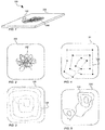
- Fig. 1 is schematical perspective view of a portion of a mechanism according to a first embodiment of the present invention.
- the mechanism comprises a ball 102 and a plate 104 and during use of the mechanism the ball will travel along a track 106 so as to compensate for detected motion of the camera.
- the mechanism itself will be associated with either an image sensor or a lens element and by shifting either of these it will be possible to affect the position of an image on the image sensor.
- the mechanism could be associated with any component in the optical system capable of affecting the optical path, such as a mirror if there is a mirror arranged in the optical path, yet in practice either the image sensor or the lens assembly will be used.
- tilt sensor e.g. an accelerometer or a gyroscope arrangement, or a combination of the two
- a processor may determine the resulting effect in motion of the image in the image plane (on the sensor) wherein a countermotion may be induced by moving the lens assembly or the image sensor (or any other component capable of affecting the beam path).
- An actuator actually inducing the countermotion may e.g. be based on electromagnetism or piezo arrangements.
- One specific type of actuators that may be used are the so called voice coil actuators, yet other types of actuators may be used as well.
- An arrangement for moving a lens or a sensor may comprise one or more ball/plate mechanisms.
- a full arrangement is likely to have three support points or more, to provide a stable arrangement. Not all support points would need to be provided with an inventive mechanism.
- Fig. 2 is a schematic plan view illustrating a situation where the present invention is not applied.
- the ball (not shown) will move in relation to the plate 104 along a path 106 as illustrated by the full line, in order to stabilize the image.
- the path 106 is not based on a real situation, it is merely based on that the camera moves arbitrarily around a central point. In a situation where the camera is fully or partially supported by e.g. a fixture or a tripod the pattern may be completely different. One effect could be that the camera will be more prone to move in one direction than in another direction. Nevertheless, from the simplified example it is apparent that there will be an excessive wear in the center of the plate 104, eventually resulting in poor performance and eventually failure of the mechanism.
- Fig. 2 Only one plate is shown in Fig. 2 (or any of the figures for that matter), yet in a normal installation there are two plates, arranged in an opposed relationship on either side of the ball; one plate is arranged on the item to be moved and another one a base.
- a plate may not form an isolated structure, it may simply be a planar portion of another structure.
- the ball in deed could be suspended in another way, e.g. in a socket, in one of the structures, in which case only one plate or planar portion would be needed.
- a hall-sensor arrangement or another mechanism may be used in order to ensure that the plate or plates return to a desired starting point after each use.
- a secondary path of motion may be applied.
- This secondary path of motion is illustrated in Fig. 3 , as a dashed line 108 on the plate 104.
- the effect of the stabilizing motion has not been considered in the view of Fig. 3 .
- the mechanism is arranged to move the ball around slowly over the surface of the plate.
- the word "slowly" is not a quantitative measure, yet there the situation is not of the type that only one single speed is possible, which will be discussed further.
- the center of the motion illustrated in Fig. 2 will continuously move around on the plate, and this will reduce the wear of the plate, or at least distribute the wear over a larger surface area of the plate 104, thus effectively increasing its lifetime.
- the wear of the ball 102 will on a general level not be affected as much, yet by manufacturing the ball from a tougher material the combined lifetime of the entire mechanism may be prolonged.
- the secondary motion will also affect the position of the image in an image plane, and this will be discussed in reference to Figs. 7 and 8 , and since this is partly related to the definition of "slowly", or lack thereof, it will be discussed there as well.
- dashed line represents the position the ball would have if no stabilization motion was applied, a "stabilization midpoint" if you will.
- stabilization motion may be applied continuously the actual path of the ball may not follow the dashed line at all. It would however cross it several times.
- the motion of the embodiment illustrated in Fig. 4 is of an intermittent nature.
- the ball remains still (in terms of secondary motion) in one position for a while, after which it moves to a new position where it remains still for a while, and so on.
- This is illustrated in the connected dots of Fig. 4 , where the dots correspond to positions where the ball is still (i.e. where there is no induced secondary motion). In each of these positions the ball may move around as illustrated in Fig. 2 so as to effect image stabilization, whereby wear distribution is accomplished.
- the secondary motion may be a combination of a continuous motion and an intermittent motion, effectively displaying a varying speed profile over time.
- Fig. 5 statistics are used in order to control the secondary motion.
- the contour lines 110 are meant to illustrate a heat map over the motion of the ball over time.
- the heat map does not have to separate the secondary motion from the image stabilizing motion, since it is the actual historical positions of the ball that is critical for the wear.
- This input may be used to control the secondary motion such that the ball is directed towards the lower right corner or the upper left corner so as to somewhat equalize the wear.
- Using the heatmap as input may be performed on many different levels of complexity, e.g.
- the heatmap (or a corresponding statistic measure) may be used continuously as input, or it may be used in temporally spaced isolated events in which a desired secondary path is calculated for the time up to the next event.
- the heatmap has been given the form of a contour map, since this is an illustrative and readily appreciable example.
- the heat map may be represented by various statistical measures, and the present invention as defined by the claims should not be limited in this respect.
- Fig. 6 illustrates a further embodiment including yet another control mechanism.
- the plate 104 is shown, and in the present embodiment the surface of the plate has been divided into three functional concentrical segments; a center segment 112, an intermediate segment 114, and an outer segment 116.
- the surface area of the plate 104 will obviously be limited, which will limit a range of motion available for the ball 102.
- Another given parameter is that when the camera moves more, i.e. when the amplitude of the motion increases; the range of motion used for the ball increases as well. This may be used as valuable input for the control of the secondary motion.
- the secondary motion will be controlled so as to move the ball 102 towards the middle of the plate 104.
- the idea is that over a certain amplitude the ball 104 will be controlled to travel to and in the center segment 112, and below a certain amplitude the ball will be controlled to travel to and in the outer segment 116, and between these amplitudes the ball 104 may be controlled to travel to and in the intermediate segment 114.
- the phrase "to and in” does not mean that the ball is controlled to travel exclusively in these segment, the motion induced to stabilize the camera may still cause the ball to travel outside of the intended area.
- three segments in the present embodiment is based on ease of explanation only, there may be more segments, such as four, five, six, etc, fewer segments, such as two, or even no segments at all.
- An example of the latter may be that a working radius for the secondary motion is a continuous, inverse, function of the amplitude of motion of the camera.
- the amplitude of motion of the camera is used as input, yet an actual function may depend on more parameters, such as frequency, statistics of the camera motion over a shorter or extended period of time, etc.
- a motion pattern as disclosed in relation to Figs. 3 or 4 may be applied. It may thus be a continuous motion, and intermittent motion, a varying speed motion, or a combination thereof.
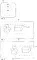
- Fig. 7 an image of a scene is exemplified. What is imaged onto the image sensor is defined by the outer rectangle 118, and what is shown on a display or at least forwarded in a video stream is defined by the inner dashed rectangle 120.
- the image sensor may be said to be oversized, yet the same effect may be accomplished by using the analogue to a digital zoom.
- the secondary motion has caused the image imaged onto the image sensor to shift in location, but due to the fact that the sensor is oversized (or digital zoom is used) the same area as before may be shown to the user.
- the shift in location between Fig. 7 and Fig. 8 would in practice be hundreds of frames apart, so that the gradual image shift caused by the secondary motion would not be detected neither by the human eye nor by detection algorithms developed to e.g. detect motion.
- the exact speed of motion for the secondary motion should preferably be such that it result in a shift of fractions of a pixel in an imaged view between adjacent image frames. Even if the speed is as low as to correspond to 1/100 of a pixel per frame, common frame rates of 30-60 frames per second (fps) will result in that the secondary motion is noticeable from a wear-reducing perspective.
- the suggested speed for the secondary motion is deduced from a practical standpoint, and from that standpoint 1/10 of a pixel per frame could be possible as well, and slower speeds as well.
- speeding the motion there is no self-evident lower limit.
- speeding up the motion eventually it may lead to artifacts in the image.
- artifacts may be corrected for, e.g. by means of deconvolution, yet that and similar corrections may be demanding from a computational standpoint, which make them less suitable in an application where there is a live feed.
- the secondary motion will in many embodiments move around the image on the image sensor and therefore a selection of an area of the sensor to be displayed to a user needs to be performed.
- the selection of the area shown to the user may be deduced from the controlled secondary motion, current settings of the lens system etc, i.e. it is predictable and may be calculated from various available input data.
- An alternative or an addition to using a predictive method as in the above paragraph may be to use digital image stabilization, e.g. a digital image stabilization based on identification and localization of features in adjacent frames.
- digital image stabilization e.g. a digital image stabilization based on identification and localization of features in adjacent frames.
- existing digital image stabilization may be supported by input from various sensors, and consequently a combination of techniques may be used for reaching the desired end result.
- An added benefit of the present invention in all of its embodiments, is that it does not require any complex technology, at least not if considered in the light of the technique available in the relevant area of technology.
- any drive unit as used for optical image stabilization today may be used, and the techniques for monitoring the position of the ball exists as well.
- the inventive purpose it is the position of the ball that is interesting, yet this information may be deduced by monitoring the position or motion of the plate or plates with which the ball interact.
- optical image stabilization may not be able to eliminate the effect of all types of shakes or vibration.
- the optical image stabilization may be used to account for stabilization of movements within a first frequency interval (which may be open at one end or more and which may comprise several interval segments), while digital image stabilization may be used to account for stabilization of movements within a second frequency interval (which may be open at one end or more and which may comprise several interval segments).
- the first and second frequency interval may be partly overlapping.
- Digital image stabilization could account for correction at higher frequencies where wither the gyro or the stabilization mechanism are too slow to respond, while the optical image stabilization accounts for correction at lower frequencies, or the other way around.
- the processor is arranged to, if an unwanted movement of the camera is detected, optically zoom out, thus enlarging the field of view as imaged on the image sensor (corresponding to the area 118 in Figs 7 and 8 .
- This will effectively increase how much the camera will be able to move before starting to affect the area shown to a user.
- the processor would also have to rescale the view shown to a user, with the aim of hiding the effects of the zoom out procedure. This procedure will increase a stabilization capability range of the mechanism, or actually of the camera comprising the mechanism.
- optically zooming out and zooming in can also be used to minimize the amount of pixels thrown away because of the difference in size between 118 and 120.
- the optical zoom can be set to make 118 and 120 of equal size. The further away from the center of the plate the secondary motion moves, the more the camera has to optically zoom out in order for all of 120 to be included in 118. The images of 120 might then be scaled to a common size in order to fit a continuous image stream.
- the zoom level may be dynamically varied based on a displacement of the ball (in its stabilizing movement), the amount of compensation needed can be minimized. In the case of cropping, this means higher resolution when the ball is closer to the center of the plate.
- Fig. 9 exemplifies an embodiment where the elimination of the effect of the secondary motion is made using hardware.
- Fig. 9 shows a camera 122 schematically suspended such that it is able to pan and tilt.
- the processor may be used to control the panning mechanism and the tilting mechanism such that the effect of the secondary motion is eliminated by a countermotion in the pan P and tilt T direction.
- the effects considered are the effects on the positioning of the image on the image chip rather than the effects of wear reduction, obviously.
- Figs 7, 8 , and 9 may be combined freely, if considered appropriate.
- the use of pan and tilt motors may be supported by digital image stabilization to reduce any residual effects.
Landscapes
- Physics & Mathematics (AREA)
- Engineering & Computer Science (AREA)
- Multimedia (AREA)
- Signal Processing (AREA)
- General Physics & Mathematics (AREA)
- Optics & Photonics (AREA)
- Computer Vision & Pattern Recognition (AREA)
- Studio Devices (AREA)
- Adjustment Of Camera Lenses (AREA)
Claims (14)
- Mechanismus zur Bildstabilisierung für eine Kamera (122), wobei der Mechanismus umfasst:einen Bewegungssensor, der Bewegung der Kamera abfühlen kann, ein Element in einem optischen Pfad der Kamera, wobei das Element ein Linsenelement oder ein Bildsensor ist,eine Kugel (102) und eine Platte (104), die als Lager wirken, wodurch sich das Element in einer Ebene bewegen kann, die rechtwinklig zu dem optischen Pfad ist,einen Aktuatormechanismus, der in der Lage ist, das Element in der Ebene zu bewegen,einen Prozessor, der konfiguriert ist, um den Aktuator zu steuern, um das Element in Reaktion auf Bewegung der Kamera zu bewegen, wie sie durch den Bewegungssensor detektiert wird, wodurch Bilder von der Kamera (122) stabilisiert werden,dadurch gekennzeichnet, dassder Prozessor ferner konfiguriert ist, um den Aktuator so zu steuern, dass das Element entlang eines sekundären Bewegungspfads (108) bewegt wird, um so einen Stabilisierungsmittelpunkt zu verschieben, um Verschleiß auf der Platte zu verteilen, der durch die Kugel erzeugt wird,wobei der Prozessor ferner in der Lage ist, eine Bildverschiebung, die durch den sekundären Bewegungspfad erzeugt wird, durch andere Mittel zur Verschiebung des Bildes zu kompensieren,wobei eine Bewegungsgeschwindigkeit der Bewegung entlang des sekundären Bewegungspfads begrenzt ist, um so zu einer Verschiebung des Sichtfeldes der Kamera zu führen, die kleiner als ein Bruchteil eines Pixels des Bildsensors pro Frame ist.
- Mechanismus zur Bildstabilisierung nach Anspruch 1, wobei das Element in dem optischen Pfad eine Linse oder einen Bildsensor umfasst.
- Mechanismus zur Bildstabilisierung nach einem der vorhergehenden Ansprüche, wobei der sekundäre Bewegungspfad (108) ein kontinuierlicher Bewegungspfad, ein intermittierender Bewegungspfad oder eine Kombination davon ist.
- Mechanismus zur Bildstabilisierung nach einem der vorhergehenden Ansprüche, wobei der Prozessor konfiguriert ist, um eine aktuelle Bewegung der Kamera als Eingabe für den zweiten Bewegungspfad zu verwenden.
- Mechanismus zur Bildstabilisierung nach einem der vorhergehenden Ansprüche, wobei der Prozessor konfiguriert ist, um eine Heatmap (110) einer Bewegung der Kugel (102) als Eingabe für den zweiten Bewegungspfad (108) zu verwenden.
- Mechanismus zur Bildstabilisierung nach einem der vorhergehenden Ansprüche, wobei die anderen Mittel zum Verschieben des Bildes (120) digitales Cropping und Skalieren umfassen.
- Mechanismus zur Bildstabilisierung nach einem der vorhergehenden Ansprüche, wobei die anderen Mittel zum Verschieben des Bildes Kameraschwenk und Kippmechanismen der Kamera umfassen.
- Bildstabilisierung nach einem der vorhergehenden Ansprüche, wobei der Prozessor vorgesehen ist, um optisches Zoomen, Skalieren und Cropping zu verwenden, um einen Stabilisierungskapazitätsbereich der Mechanismen zur Bildstabilisierung zu vergrößern.
- Verfahren zum Steuern eines Stabilisierungsmechanismus für eine Kamera, umfassend einen Mechanismus zur Bildstabilisierung gemäß einem der vorhergehenden Ansprüche, und:Detektieren einer Bewegung der Kamera mittels eines Bewegungssensors,Weiterleiten von Informationen über die Bewegung zu einem Prozessor der Kamera,Steuern eines Aktuators zum Bewegen des Elements in einen optischen Pfad unter Verwendung des Prozessors, um so der Bewegung der Kamera entgegen zu wirken,Steuern des Aktuators unter Verwendung des Prozessors, um das Element entlang eines sekundären Bewegungspfads in den optischen Pfad zu bewegen, um so Verschleiß auf der Platte zu verteilen, welcher durch die Kugel erzeugt wird,wobei das Element durch eine Aufhängung aus Kugel (102) und Platte (104) aufgehängt ist.
- Verfahren nach Anspruch 9, wobei der sekundäre Bewegungspfad ein kontinuierlicher Bewegungspfad, ein intermittierender Bewegungspfad oder eine Kombination davon ist.
- Verfahren nach Anspruch 9 oder 10, ferner umfassend Bewegen des Elements entlang des sekundären Bewegungspfads mit einer begrenzten Geschwindigkeit, so dass der Effekt auf einen Bildsensor der Kamera auf Bruchteile eines Pixels pro Frame begrenzt ist.
- Verfahren nach einem der Ansprüche 9 bis 11, das eine Bewegung der Kamera als Eingabe für den sekundären Bewegungspfad verwendet.
- Verfahren nach einem der Ansprüche 9 bis 12, das eine Heatmap (110) der Bewegung der Kugel als Eingabe für den sekundären Bewegungspfad verwendet.
- Computerprogrammprodukt, umfassend ein computerlesbares Speichermedium mit Anweisungen, die zum Durchführen des Verfahrens gemäß einem der Ansprüche 10 bis 13 adaptiert sind, wenn sie durch einen Prozessor ausgeführt werden.
Priority Applications (6)
| Application Number | Priority Date | Filing Date | Title |
|---|---|---|---|
| EP15170472.3A EP3101890B1 (de) | 2015-06-03 | 2015-06-03 | Mechanismus und verfahren zur optischen bildstabilisierung |
| JP2016102990A JP6710102B2 (ja) | 2015-06-03 | 2016-05-24 | 光学画像安定化のための機構及び方法 |
| KR1020160065767A KR102173097B1 (ko) | 2015-06-03 | 2016-05-27 | 광학 이미지 안정화에 대한 메커니즘 및 방법 |
| CN201610363979.8A CN106254758B (zh) | 2015-06-03 | 2016-05-27 | 用于光学图像稳定的机构和方法 |
| US15/171,496 US10091425B2 (en) | 2015-06-03 | 2016-06-02 | Mechanism and a method for optical image stabilization for a camera that moves an element to counteract motion of the camera |
| TW105117662A TWI735445B (zh) | 2015-06-03 | 2016-06-03 | 光學影像穩定化之機構與方法 |
Applications Claiming Priority (1)
| Application Number | Priority Date | Filing Date | Title |
|---|---|---|---|
| EP15170472.3A EP3101890B1 (de) | 2015-06-03 | 2015-06-03 | Mechanismus und verfahren zur optischen bildstabilisierung |
Publications (2)
| Publication Number | Publication Date |
|---|---|
| EP3101890A1 EP3101890A1 (de) | 2016-12-07 |
| EP3101890B1 true EP3101890B1 (de) | 2017-11-22 |
Family
ID=53432985
Family Applications (1)
| Application Number | Title | Priority Date | Filing Date |
|---|---|---|---|
| EP15170472.3A Active EP3101890B1 (de) | 2015-06-03 | 2015-06-03 | Mechanismus und verfahren zur optischen bildstabilisierung |
Country Status (6)
| Country | Link |
|---|---|
| US (1) | US10091425B2 (de) |
| EP (1) | EP3101890B1 (de) |
| JP (1) | JP6710102B2 (de) |
| KR (1) | KR102173097B1 (de) |
| CN (1) | CN106254758B (de) |
| TW (1) | TWI735445B (de) |
Families Citing this family (1)
| Publication number | Priority date | Publication date | Assignee | Title |
|---|---|---|---|---|
| WO2019065822A1 (ja) * | 2017-09-28 | 2019-04-04 | 富士フイルム株式会社 | 撮像装置、その作動方法および作動プログラム |
Family Cites Families (33)
| Publication number | Priority date | Publication date | Assignee | Title |
|---|---|---|---|---|
| US6992700B1 (en) * | 1998-09-08 | 2006-01-31 | Ricoh Company, Ltd. | Apparatus for correction based upon detecting a camera shaking |
| CN1802583A (zh) * | 2003-06-09 | 2006-07-12 | 奥林巴斯株式会社 | 可变镜 |
| DE102004045430A1 (de) * | 2004-09-18 | 2006-05-18 | Deutsche Telekom Ag | Vorrichtung zur Bildstabilisierung |
| US20070102622A1 (en) * | 2005-07-01 | 2007-05-10 | Olsen Richard I | Apparatus for multiple camera devices and method of operating same |
| CN101317119A (zh) * | 2005-11-30 | 2008-12-03 | 诺基亚公司 | 用于图像稳定的方法和系统 |
| JP2007163594A (ja) * | 2005-12-09 | 2007-06-28 | Canon Inc | 光学機器および撮像システム |
| JP2008233526A (ja) * | 2007-03-20 | 2008-10-02 | Tamron Co Ltd | 像振れ防止用アクチュエータ及びそれを備えたカメラ |
| US7978222B2 (en) * | 2008-03-01 | 2011-07-12 | Avago Technologies Ecbu Ip (Singapore) Pte. Ltd. | Systems and methods for image stabilization |
| JP4462372B2 (ja) * | 2008-06-13 | 2010-05-12 | ソニー株式会社 | ブレ補正ユニットおよび撮像装置 |
| JP5096496B2 (ja) * | 2008-07-24 | 2012-12-12 | パナソニック株式会社 | カメラ駆動装置 |
| US8571399B2 (en) * | 2008-10-14 | 2013-10-29 | Nidec Sankyo Corporation | Photographic optical device |
| US8442392B2 (en) * | 2009-12-22 | 2013-05-14 | Nokia Corporation | Method and apparatus for operating the automatic focus or the optical imaging stabilizing system |
| JP5593118B2 (ja) * | 2010-04-30 | 2014-09-17 | 日本電産サンキョー株式会社 | 振れ補正機能付き光学ユニット |
| WO2011155318A1 (ja) * | 2010-06-08 | 2011-12-15 | 日本電産サンキョー株式会社 | 振れ補正装置、撮影用光学装置およびレンズ駆動装置 |
| JP5622443B2 (ja) * | 2010-06-08 | 2014-11-12 | 日本電産サンキョー株式会社 | 振れ補正機能付き光学ユニット |
| JP5580684B2 (ja) | 2010-07-29 | 2014-08-27 | オリンパスイメージング株式会社 | 像振れ補正装置及びカメラ |
| TWI409577B (zh) * | 2010-08-20 | 2013-09-21 | Primax Electronics Ltd | 光學影像系統 |
| US8711235B2 (en) * | 2011-05-16 | 2014-04-29 | Rpx Corporation | Image stabilization |
| TWI529471B (zh) * | 2011-05-20 | 2016-04-11 | 鴻海精密工業股份有限公司 | 影像穩定模組及成像裝置 |
| JP5848052B2 (ja) * | 2011-07-21 | 2016-01-27 | 日本電産サンキョー株式会社 | 振れ補正機能付き光学ユニット |
| US8855476B2 (en) * | 2011-09-28 | 2014-10-07 | DigitalOptics Corporation MEMS | MEMS-based optical image stabilization |
| EP2611151B1 (de) * | 2011-12-29 | 2014-01-22 | Axis AB | Verfahren und mobile Einheit zur leichteren Installation einer Überwachungskamera |
| KR101975893B1 (ko) * | 2012-03-21 | 2019-09-10 | 엘지이노텍 주식회사 | 카메라 모듈 |
| US9134503B2 (en) * | 2012-07-06 | 2015-09-15 | Apple Inc. | VCM OIS actuator module |
| US9398264B2 (en) * | 2012-10-19 | 2016-07-19 | Qualcomm Incorporated | Multi-camera system using folded optics |
| JP2015036716A (ja) * | 2013-08-12 | 2015-02-23 | ソニー株式会社 | 像ぶれ補正装置及び撮像装置 |
| CN104519239A (zh) * | 2013-09-29 | 2015-04-15 | 诺基亚公司 | 用于视频防抖的方法和装置 |
| CN203745777U (zh) * | 2014-01-10 | 2014-07-30 | 瑞声声学科技(深圳)有限公司 | 阵列式镜头装置 |
| KR101433846B1 (ko) | 2014-03-14 | 2014-08-26 | 주식회사 퓨런티어 | 광학 이미지 안정화 모듈의 검사 장치 및 방법 |
| US9541740B2 (en) * | 2014-06-20 | 2017-01-10 | Qualcomm Incorporated | Folded optic array camera using refractive prisms |
| CN204086644U (zh) * | 2014-08-25 | 2015-01-07 | 瑞声精密制造科技(常州)有限公司 | 镜头驱动装置 |
| US9832381B2 (en) * | 2014-10-31 | 2017-11-28 | Qualcomm Incorporated | Optical image stabilization for thin cameras |
| CN204287688U (zh) * | 2014-12-19 | 2015-04-22 | 深圳市世尊科技有限公司 | 一种通过纯平移运动实现光学防抖的音圈马达 |
-
2015
- 2015-06-03 EP EP15170472.3A patent/EP3101890B1/de active Active
-
2016
- 2016-05-24 JP JP2016102990A patent/JP6710102B2/ja active Active
- 2016-05-27 CN CN201610363979.8A patent/CN106254758B/zh active Active
- 2016-05-27 KR KR1020160065767A patent/KR102173097B1/ko active Active
- 2016-06-02 US US15/171,496 patent/US10091425B2/en active Active
- 2016-06-03 TW TW105117662A patent/TWI735445B/zh active
Non-Patent Citations (1)
| Title |
|---|
| None * |
Also Published As
| Publication number | Publication date |
|---|---|
| JP2017032977A (ja) | 2017-02-09 |
| EP3101890A1 (de) | 2016-12-07 |
| TW201703507A (zh) | 2017-01-16 |
| KR102173097B1 (ko) | 2020-11-02 |
| CN106254758B (zh) | 2020-03-13 |
| US20160360113A1 (en) | 2016-12-08 |
| TWI735445B (zh) | 2021-08-11 |
| JP6710102B2 (ja) | 2020-06-17 |
| KR20160142773A (ko) | 2016-12-13 |
| US10091425B2 (en) | 2018-10-02 |
| CN106254758A (zh) | 2016-12-21 |
Similar Documents
| Publication | Publication Date | Title |
|---|---|---|
| US10063818B1 (en) | Methods and systems for projecting a target portion of an image at a higher resolution | |
| KR101901104B1 (ko) | 오토매틱 줌을 수행하기 위한 시스템들 및 방법들 | |
| JP4245185B2 (ja) | 撮像装置 | |
| US11394881B2 (en) | Image processing apparatus, image processing method, storage medium, system, and electronic apparatus | |
| EP3096512B1 (de) | Verfahren und apparat zur herstellung eines stabilisierten videos | |
| CN112930678A (zh) | 光学图像稳定技术 | |
| KR20190141709A (ko) | 눈 추적을 통한 확장된 유효 아이박스를 포함하는 근안 디스플레이 | |
| TW202034675A (zh) | 光學影像穩定技術 | |
| CN104469139A (zh) | 图像捕获装置和图像捕获方法 | |
| JP7456043B2 (ja) | 撮像支援装置、撮像支援システム、撮像システム、撮像支援方法、及びプログラム | |
| JP2023175995A5 (de) | ||
| EP3101890B1 (de) | Mechanismus und verfahren zur optischen bildstabilisierung | |
| JP4621726B2 (ja) | 手ぶれ補正装置、手ぶれ補正プログラム、撮像装置、撮像プログラム | |
| JP7646389B2 (ja) | 撮像装置、コンピュータプログラム、記憶媒体及び撮像装置の制御方法 | |
| US10075643B2 (en) | Shakiness correcting method and apparatus | |
| US11677911B2 (en) | Display apparatus capable of controlling a position of a display range based on a change of focal distance | |
| WO2019151030A1 (ja) | 撮像装置、固体撮像素子、カメラモジュール、駆動制御部、および撮像方法 | |
| JP2021100239A (ja) | 追尾装置及びその制御方法、及び撮像装置 | |
| JP5393877B2 (ja) | 撮像装置および集積回路 | |
| JP6241240B2 (ja) | 画像揺れ防止装置及びカメラシステム | |
| KR101218771B1 (ko) | 조향 거울에 의한 상번짐 방지 항공 촬영 시스템 | |
| US8786677B2 (en) | Imaging device | |
| JP2013197822A (ja) | 撮像装置、その制御方法、および制御プログラム | |
| JP2017032977A5 (de) | ||
| JP6188369B2 (ja) | 撮像装置 |
Legal Events
| Date | Code | Title | Description |
|---|---|---|---|
| PUAI | Public reference made under article 153(3) epc to a published international application that has entered the european phase |
Free format text: ORIGINAL CODE: 0009012 |
|
| STAA | Information on the status of an ep patent application or granted ep patent |
Free format text: STATUS: REQUEST FOR EXAMINATION WAS MADE |
|
| 17P | Request for examination filed |
Effective date: 20161027 |
|
| AK | Designated contracting states |
Kind code of ref document: A1 Designated state(s): AL AT BE BG CH CY CZ DE DK EE ES FI FR GB GR HR HU IE IS IT LI LT LU LV MC MK MT NL NO PL PT RO RS SE SI SK SM TR |
|
| AX | Request for extension of the european patent |
Extension state: BA ME |
|
| STAA | Information on the status of an ep patent application or granted ep patent |
Free format text: STATUS: EXAMINATION IS IN PROGRESS |
|
| 17Q | First examination report despatched |
Effective date: 20170130 |
|
| GRAP | Despatch of communication of intention to grant a patent |
Free format text: ORIGINAL CODE: EPIDOSNIGR1 |
|
| STAA | Information on the status of an ep patent application or granted ep patent |
Free format text: STATUS: GRANT OF PATENT IS INTENDED |
|
| INTG | Intention to grant announced |
Effective date: 20170724 |
|
| GRAS | Grant fee paid |
Free format text: ORIGINAL CODE: EPIDOSNIGR3 |
|
| GRAA | (expected) grant |
Free format text: ORIGINAL CODE: 0009210 |
|
| STAA | Information on the status of an ep patent application or granted ep patent |
Free format text: STATUS: THE PATENT HAS BEEN GRANTED |
|
| AK | Designated contracting states |
Kind code of ref document: B1 Designated state(s): AL AT BE BG CH CY CZ DE DK EE ES FI FR GB GR HR HU IE IS IT LI LT LU LV MC MK MT NL NO PL PT RO RS SE SI SK SM TR |
|
| REG | Reference to a national code |
Ref country code: GB Ref legal event code: FG4D |
|
| REG | Reference to a national code |
Ref country code: CH Ref legal event code: EP |
|
| REG | Reference to a national code |
Ref country code: IE Ref legal event code: FG4D |
|
| REG | Reference to a national code |
Ref country code: AT Ref legal event code: REF Ref document number: 949401 Country of ref document: AT Kind code of ref document: T Effective date: 20171215 |
|
| REG | Reference to a national code |
Ref country code: DE Ref legal event code: R096 Ref document number: 602015006117 Country of ref document: DE |
|
| REG | Reference to a national code |
Ref country code: SE Ref legal event code: TRGR |
|
| REG | Reference to a national code |
Ref country code: NL Ref legal event code: MP Effective date: 20171122 |
|
| REG | Reference to a national code |
Ref country code: LT Ref legal event code: MG4D |
|
| REG | Reference to a national code |
Ref country code: AT Ref legal event code: MK05 Ref document number: 949401 Country of ref document: AT Kind code of ref document: T Effective date: 20171122 |
|
| PG25 | Lapsed in a contracting state [announced via postgrant information from national office to epo] |
Ref country code: FI Free format text: LAPSE BECAUSE OF FAILURE TO SUBMIT A TRANSLATION OF THE DESCRIPTION OR TO PAY THE FEE WITHIN THE PRESCRIBED TIME-LIMIT Effective date: 20171122 Ref country code: LT Free format text: LAPSE BECAUSE OF FAILURE TO SUBMIT A TRANSLATION OF THE DESCRIPTION OR TO PAY THE FEE WITHIN THE PRESCRIBED TIME-LIMIT Effective date: 20171122 Ref country code: ES Free format text: LAPSE BECAUSE OF FAILURE TO SUBMIT A TRANSLATION OF THE DESCRIPTION OR TO PAY THE FEE WITHIN THE PRESCRIBED TIME-LIMIT Effective date: 20171122 Ref country code: NL Free format text: LAPSE BECAUSE OF FAILURE TO SUBMIT A TRANSLATION OF THE DESCRIPTION OR TO PAY THE FEE WITHIN THE PRESCRIBED TIME-LIMIT Effective date: 20171122 Ref country code: NO Free format text: LAPSE BECAUSE OF FAILURE TO SUBMIT A TRANSLATION OF THE DESCRIPTION OR TO PAY THE FEE WITHIN THE PRESCRIBED TIME-LIMIT Effective date: 20180222 |
|
| REG | Reference to a national code |
Ref country code: FR Ref legal event code: PLFP Year of fee payment: 4 |
|
| PG25 | Lapsed in a contracting state [announced via postgrant information from national office to epo] |
Ref country code: GR Free format text: LAPSE BECAUSE OF FAILURE TO SUBMIT A TRANSLATION OF THE DESCRIPTION OR TO PAY THE FEE WITHIN THE PRESCRIBED TIME-LIMIT Effective date: 20180223 Ref country code: HR Free format text: LAPSE BECAUSE OF FAILURE TO SUBMIT A TRANSLATION OF THE DESCRIPTION OR TO PAY THE FEE WITHIN THE PRESCRIBED TIME-LIMIT Effective date: 20171122 Ref country code: RS Free format text: LAPSE BECAUSE OF FAILURE TO SUBMIT A TRANSLATION OF THE DESCRIPTION OR TO PAY THE FEE WITHIN THE PRESCRIBED TIME-LIMIT Effective date: 20171122 Ref country code: LV Free format text: LAPSE BECAUSE OF FAILURE TO SUBMIT A TRANSLATION OF THE DESCRIPTION OR TO PAY THE FEE WITHIN THE PRESCRIBED TIME-LIMIT Effective date: 20171122 Ref country code: BG Free format text: LAPSE BECAUSE OF FAILURE TO SUBMIT A TRANSLATION OF THE DESCRIPTION OR TO PAY THE FEE WITHIN THE PRESCRIBED TIME-LIMIT Effective date: 20180222 Ref country code: AT Free format text: LAPSE BECAUSE OF FAILURE TO SUBMIT A TRANSLATION OF THE DESCRIPTION OR TO PAY THE FEE WITHIN THE PRESCRIBED TIME-LIMIT Effective date: 20171122 |
|
| PG25 | Lapsed in a contracting state [announced via postgrant information from national office to epo] |
Ref country code: CZ Free format text: LAPSE BECAUSE OF FAILURE TO SUBMIT A TRANSLATION OF THE DESCRIPTION OR TO PAY THE FEE WITHIN THE PRESCRIBED TIME-LIMIT Effective date: 20171122 Ref country code: SK Free format text: LAPSE BECAUSE OF FAILURE TO SUBMIT A TRANSLATION OF THE DESCRIPTION OR TO PAY THE FEE WITHIN THE PRESCRIBED TIME-LIMIT Effective date: 20171122 Ref country code: DK Free format text: LAPSE BECAUSE OF FAILURE TO SUBMIT A TRANSLATION OF THE DESCRIPTION OR TO PAY THE FEE WITHIN THE PRESCRIBED TIME-LIMIT Effective date: 20171122 Ref country code: EE Free format text: LAPSE BECAUSE OF FAILURE TO SUBMIT A TRANSLATION OF THE DESCRIPTION OR TO PAY THE FEE WITHIN THE PRESCRIBED TIME-LIMIT Effective date: 20171122 Ref country code: CY Free format text: LAPSE BECAUSE OF FAILURE TO SUBMIT A TRANSLATION OF THE DESCRIPTION OR TO PAY THE FEE WITHIN THE PRESCRIBED TIME-LIMIT Effective date: 20171122 |
|
| REG | Reference to a national code |
Ref country code: DE Ref legal event code: R097 Ref document number: 602015006117 Country of ref document: DE |
|
| PG25 | Lapsed in a contracting state [announced via postgrant information from national office to epo] |
Ref country code: IT Free format text: LAPSE BECAUSE OF FAILURE TO SUBMIT A TRANSLATION OF THE DESCRIPTION OR TO PAY THE FEE WITHIN THE PRESCRIBED TIME-LIMIT Effective date: 20171122 Ref country code: PL Free format text: LAPSE BECAUSE OF FAILURE TO SUBMIT A TRANSLATION OF THE DESCRIPTION OR TO PAY THE FEE WITHIN THE PRESCRIBED TIME-LIMIT Effective date: 20171122 Ref country code: SM Free format text: LAPSE BECAUSE OF FAILURE TO SUBMIT A TRANSLATION OF THE DESCRIPTION OR TO PAY THE FEE WITHIN THE PRESCRIBED TIME-LIMIT Effective date: 20171122 |
|
| PLBE | No opposition filed within time limit |
Free format text: ORIGINAL CODE: 0009261 |
|
| STAA | Information on the status of an ep patent application or granted ep patent |
Free format text: STATUS: NO OPPOSITION FILED WITHIN TIME LIMIT |
|
| 26N | No opposition filed |
Effective date: 20180823 |
|
| PG25 | Lapsed in a contracting state [announced via postgrant information from national office to epo] |
Ref country code: SI Free format text: LAPSE BECAUSE OF FAILURE TO SUBMIT A TRANSLATION OF THE DESCRIPTION OR TO PAY THE FEE WITHIN THE PRESCRIBED TIME-LIMIT Effective date: 20171122 |
|
| REG | Reference to a national code |
Ref country code: CH Ref legal event code: PL |
|
| REG | Reference to a national code |
Ref country code: BE Ref legal event code: MM Effective date: 20180630 |
|
| REG | Reference to a national code |
Ref country code: IE Ref legal event code: MM4A |
|
| PG25 | Lapsed in a contracting state [announced via postgrant information from national office to epo] |
Ref country code: MC Free format text: LAPSE BECAUSE OF FAILURE TO SUBMIT A TRANSLATION OF THE DESCRIPTION OR TO PAY THE FEE WITHIN THE PRESCRIBED TIME-LIMIT Effective date: 20171122 Ref country code: LU Free format text: LAPSE BECAUSE OF NON-PAYMENT OF DUE FEES Effective date: 20180603 |
|
| PG25 | Lapsed in a contracting state [announced via postgrant information from national office to epo] |
Ref country code: CH Free format text: LAPSE BECAUSE OF NON-PAYMENT OF DUE FEES Effective date: 20180630 Ref country code: LI Free format text: LAPSE BECAUSE OF NON-PAYMENT OF DUE FEES Effective date: 20180630 Ref country code: IE Free format text: LAPSE BECAUSE OF NON-PAYMENT OF DUE FEES Effective date: 20180603 |
|
| PG25 | Lapsed in a contracting state [announced via postgrant information from national office to epo] |
Ref country code: BE Free format text: LAPSE BECAUSE OF NON-PAYMENT OF DUE FEES Effective date: 20180630 |
|
| PG25 | Lapsed in a contracting state [announced via postgrant information from national office to epo] |
Ref country code: MT Free format text: LAPSE BECAUSE OF NON-PAYMENT OF DUE FEES Effective date: 20180603 |
|
| PG25 | Lapsed in a contracting state [announced via postgrant information from national office to epo] |
Ref country code: TR Free format text: LAPSE BECAUSE OF FAILURE TO SUBMIT A TRANSLATION OF THE DESCRIPTION OR TO PAY THE FEE WITHIN THE PRESCRIBED TIME-LIMIT Effective date: 20171122 |
|
| PG25 | Lapsed in a contracting state [announced via postgrant information from national office to epo] |
Ref country code: PT Free format text: LAPSE BECAUSE OF FAILURE TO SUBMIT A TRANSLATION OF THE DESCRIPTION OR TO PAY THE FEE WITHIN THE PRESCRIBED TIME-LIMIT Effective date: 20171122 |
|
| PG25 | Lapsed in a contracting state [announced via postgrant information from national office to epo] |
Ref country code: RO Free format text: LAPSE BECAUSE OF FAILURE TO SUBMIT A TRANSLATION OF THE DESCRIPTION OR TO PAY THE FEE WITHIN THE PRESCRIBED TIME-LIMIT Effective date: 20171122 Ref country code: HU Free format text: LAPSE BECAUSE OF FAILURE TO SUBMIT A TRANSLATION OF THE DESCRIPTION OR TO PAY THE FEE WITHIN THE PRESCRIBED TIME-LIMIT; INVALID AB INITIO Effective date: 20150603 Ref country code: MK Free format text: LAPSE BECAUSE OF NON-PAYMENT OF DUE FEES Effective date: 20171122 |
|
| PG25 | Lapsed in a contracting state [announced via postgrant information from national office to epo] |
Ref country code: AL Free format text: LAPSE BECAUSE OF FAILURE TO SUBMIT A TRANSLATION OF THE DESCRIPTION OR TO PAY THE FEE WITHIN THE PRESCRIBED TIME-LIMIT Effective date: 20171122 Ref country code: IS Free format text: LAPSE BECAUSE OF FAILURE TO SUBMIT A TRANSLATION OF THE DESCRIPTION OR TO PAY THE FEE WITHIN THE PRESCRIBED TIME-LIMIT Effective date: 20180322 |
|
| REG | Reference to a national code |
Ref country code: DE Ref legal event code: R079 Ref document number: 602015006117 Country of ref document: DE Free format text: PREVIOUS MAIN CLASS: H04N0005232000 Ipc: H04N0023600000 |
|
| P01 | Opt-out of the competence of the unified patent court (upc) registered |
Effective date: 20230505 |
|
| PGFP | Annual fee paid to national office [announced via postgrant information from national office to epo] |
Ref country code: DE Payment date: 20250520 Year of fee payment: 11 |
|
| PGFP | Annual fee paid to national office [announced via postgrant information from national office to epo] |
Ref country code: GB Payment date: 20250520 Year of fee payment: 11 |
|
| PGFP | Annual fee paid to national office [announced via postgrant information from national office to epo] |
Ref country code: FR Payment date: 20250520 Year of fee payment: 11 |
|
| PGFP | Annual fee paid to national office [announced via postgrant information from national office to epo] |
Ref country code: SE Payment date: 20250520 Year of fee payment: 11 |