EP3101977A1 - Mobilkommunikationssystem und benutzerendgerät - Google Patents
Mobilkommunikationssystem und benutzerendgerät Download PDFInfo
- Publication number
- EP3101977A1 EP3101977A1 EP15744019.9A EP15744019A EP3101977A1 EP 3101977 A1 EP3101977 A1 EP 3101977A1 EP 15744019 A EP15744019 A EP 15744019A EP 3101977 A1 EP3101977 A1 EP 3101977A1
- Authority
- EP
- European Patent Office
- Prior art keywords
- resource
- data
- information
- data resource
- user terminal
- Prior art date
- Legal status (The legal status is an assumption and is not a legal conclusion. Google has not performed a legal analysis and makes no representation as to the accuracy of the status listed.)
- Withdrawn
Links
- 238000010295 mobile communication Methods 0.000 title claims abstract description 36
- 230000006854 communication Effects 0.000 claims abstract description 90
- 238000004891 communication Methods 0.000 claims abstract description 89
- 238000000034 method Methods 0.000 description 32
- 230000005540 biological transmission Effects 0.000 description 27
- 238000010586 diagram Methods 0.000 description 26
- 230000008569 process Effects 0.000 description 24
- 238000012986 modification Methods 0.000 description 9
- 230000004048 modification Effects 0.000 description 9
- 230000006870 function Effects 0.000 description 8
- 238000013468 resource allocation Methods 0.000 description 7
- 230000010267 cellular communication Effects 0.000 description 6
- 238000007726 management method Methods 0.000 description 4
- 230000006835 compression Effects 0.000 description 2
- 238000007906 compression Methods 0.000 description 2
- 238000013461 design Methods 0.000 description 2
- 238000012423 maintenance Methods 0.000 description 2
- 238000013507 mapping Methods 0.000 description 2
- 230000004044 response Effects 0.000 description 2
- 238000012546 transfer Methods 0.000 description 2
- 125000004122 cyclic group Chemical group 0.000 description 1
- 230000006837 decompression Effects 0.000 description 1
- 238000001514 detection method Methods 0.000 description 1
- 230000000694 effects Effects 0.000 description 1
- 238000005259 measurement Methods 0.000 description 1
- 238000012544 monitoring process Methods 0.000 description 1
- NRNCYVBFPDDJNE-UHFFFAOYSA-N pemoline Chemical compound O1C(N)=NC(=O)C1C1=CC=CC=C1 NRNCYVBFPDDJNE-UHFFFAOYSA-N 0.000 description 1
- 230000000737 periodic effect Effects 0.000 description 1
- 230000002093 peripheral effect Effects 0.000 description 1
- 238000012545 processing Methods 0.000 description 1
- 230000009467 reduction Effects 0.000 description 1
- 230000001360 synchronised effect Effects 0.000 description 1
Images






Classifications
-
- H—ELECTRICITY
- H04—ELECTRIC COMMUNICATION TECHNIQUE
- H04W—WIRELESS COMMUNICATION NETWORKS
- H04W72/00—Local resource management
- H04W72/04—Wireless resource allocation
- H04W72/044—Wireless resource allocation based on the type of the allocated resource
-
- H—ELECTRICITY
- H04—ELECTRIC COMMUNICATION TECHNIQUE
- H04W—WIRELESS COMMUNICATION NETWORKS
- H04W72/00—Local resource management
- H04W72/20—Control channels or signalling for resource management
-
- H—ELECTRICITY
- H04—ELECTRIC COMMUNICATION TECHNIQUE
- H04W—WIRELESS COMMUNICATION NETWORKS
- H04W72/00—Local resource management
- H04W72/04—Wireless resource allocation
- H04W72/044—Wireless resource allocation based on the type of the allocated resource
- H04W72/0446—Resources in time domain, e.g. slots or frames
-
- H—ELECTRICITY
- H04—ELECTRIC COMMUNICATION TECHNIQUE
- H04W—WIRELESS COMMUNICATION NETWORKS
- H04W76/00—Connection management
- H04W76/10—Connection setup
- H04W76/14—Direct-mode setup
-
- H—ELECTRICITY
- H04—ELECTRIC COMMUNICATION TECHNIQUE
- H04W—WIRELESS COMMUNICATION NETWORKS
- H04W8/00—Network data management
- H04W8/005—Discovery of network devices, e.g. terminals
Definitions
- the present invention relates to a mobile communication system and a user terminal that supports D2D proximity service.
- the D2D proximity service (D2D ProSe) is a service enabling direct communication without passing through a network within a synchronization cluster including a plurality of synchronized user terminals.
- the D2D proximity service includes a discovery process (Discovery) in which a proximal terminal is discovered and a communication process (Communication) in which direct communication is performed.
- the D2D communication is performed to reduce a load of a base station or when a user terminal is out of coverage, for example.
- a user terminal decides a time-frequency resource (hereinafter, referred to as a data resource, where appropriate) used for transmitting D2D communication data, it may be considered that in order to inform peripheral user terminals of the decided data resource, the user terminal transmits control information indicating a position of the decided data resource.
- an object of the present invention is to provide a mobile communication system and a user terminal with which a user terminal is capable of appropriately deciding a data resource used for transmitting D2D communication data.
- a mobile communication system is a mobile communication system that supports a D2D proximity service in which direct communication not passing through a network is enabled, comprising a user terminal configured to decide a data resource that is a time-frequency resource used for transmitting D2D communication data, and a control resource that is a time-frequency resource used for transmitting control information indicating a position of the data resource, from among time-frequency resources available for the D2D proximity service, wherein the user terminal is further configured to decide the data resource from a data resource domain limited in range in the time-frequency resources available for the D2D proximity service.
- a mobile communication system is a mobile communication system that supports a D2D proximity service in which direct communication not passing through a network is enabled, comprising a user terminal configured to decide a data resource that is a time-frequency resource used for transmitting D2D communication data, and a control resource that is a time-frequency resource used for transmitting control information indicating a position of the data resource, from among time-frequency resources available for the D2D proximity service, wherein the user terminal is further configured to decide the data resource from a data resource domain limited in range in the time-frequency resources available for the D2D proximity service.
- the mobile communication system comprises a base station configured to transmit, to the user terminal, data resource information for specifying the data resource domain, the data resource, or a candidate of the data resource domain.
- the data resource information is information for specifying the data resource
- the base station is further configured to transmit the data resource information by using downlink control information.
- the data resource information is information for specifying a range of the data resource
- the base station transmits the data resource information by using an RRC message.
- the user terminal is further configured to decide the control resource from a control resource domain limited in range in the time-frequency resources available for the D2D proximity service
- the base station is further configured to transmit the data resource information by unicast, to the user terminal, together with control resource information specifying the control resource domain, the control resource, or a candidate of the control resource domain.
- the base station is further configured to transmit the data resource information by broadcast, and the data resource information includes information for limiting at least one of a position of the data resource and a size of the data resource.
- the user terminal when the user terminal exists in a cell managed by the base station, the user terminal is further configured to transmit the data resource information received from the base station.
- the mobile communication system comprises another user terminal located out of coverage, the user terminal is further configured to transmit the data resource information to the another user terminal, when the user terminal receives, from the another user terminal, flag information indicating that the another user terminal is located out of coverage,
- the mobile communication system comprises another user terminal that previously stores setting information for limiting a range of the data resource domain and is located out of coverage, when the other user terminal receives the data resource information from the user terminal, the other user terminal prioritizes the data resource information over the setting information to decide the data resource.
- the user terminal is further configured to decide the data resource on the basis of a position of the control resource and/or a size of the control resource.
- a control resource domain that is a range in which the user terminal decides the control resource, is provided periodically in a time axis direction, a range of a control resource domain in a next period is limited depending on a position of a control resource in a previous period and a range of the data resource domain is limited depending on the position of the control resource, and the user terminal is further configured to decide the data resource depending on the position of the control resource in the previous period.
- the user terminal is further configured to use the control resource to transmit, together with the control information, flag information indicating whether or not the user terminal is located out of coverage.
- a mobile communication system is a mobile communication system that supports a D2D proximity service in which direct communication not passing through a network is enabled, comprising a user terminal configured to decide a data resource that is a time-frequency resource used for transmitting D2D communication data, and a control resource that is a time-frequency resource used for transmitting control information indicating a position of the data resource, from among time-frequency resources available for the D2D proximity service, wherein the user terminal is further configured to use the decided data resource to repeatedly transmit the same D2D communication data at a bit level or in units of resource blocks.
- a user terminal is a user terminal used in a mobile communication system that supports a D2D proximity service in which direct communication not passing through a network is enabled, comprising a controller configured to decide a data resource that is a time-frequency resource used for transmitting D2D communication data, and a control resource that is a time-frequency resource used for transmitting control information indicating a position of the data resource, from among time-frequency resources available for the D2D proximity service, wherein the controller is further configured to decide the data resource from a data resource domain limited in range in the time-frequency resources available for the D2D proximity service.
- Fig. 1 is a configuration diagram of an LTE system according to the present embodiment.
- the LTE system includes a plurality of UEs (User Equipments) 100, E-UTRAN (Evolved-Universal Terrestrial Radio Access Network) 10, and EPC (Evolved Packet Core) 20.
- the E-UTRAN 10 and the EPC 20 constitute a network.
- the UE 100 is a mobile radio communication device and performs radio communication with a cell (a serving cell) with which a connection is established.
- the UE 100 corresponds to the user terminal.
- the E-UTRAN 10 includes a plurality of eNBs 200 (evolved Node-Bs). Each eNB 200 corresponds to a base station. The eNB 200 manages a cell and performs radio communication with the UE 100 that establishes a connection with the cell.
- eNBs 200 evolved Node-Bs
- the "cell” is used as a term indicating a minimum unit of a radio communication area, and is also used as a term indicating a function of performing radio communication with the UE 100.
- the eNB 200 for example, has a radio resource management (RRM) function, a function of routing user data, and a measurement control function for mobility control and scheduling.
- RRM radio resource management
- the EPC 20 includes MME (Mobility Management Entity)/S-GWs (Serving-Gateways) 300, and OAM 400 (Operation and Maintenance). Further, the EPC 20 corresponds to a core network.
- MME Mobility Management Entity
- S-GWs Server-Gateways
- OAM 400 Operaation and Maintenance
- the MME is a network node that performs various mobility controls and the like, for the UE 100 and corresponds to a controller.
- the S-GW is a network node that performs control to transfer user data and corresponds to a mobile switching center.
- the OAM 400 is a server device managed by an operator and performs maintenance and monitoring of the E-UTRAN 10.
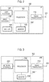
- Fig. 2 is a block diagram of the UE 100.
- the UE 100 includes an antenna 101, a radio transceiver 110, a user interface 120, a GNSS (Global Navigation Satellite System) receiver 130, a battery 140, a memory 150, and a processor 160.
- the memory 150 and the processor 160 constitute a control unit.
- the UE 100 may not have the GNSS receiver 130. Furthermore, the memory 150 may be integrally formed with the processor 160, and this set (that is, a chip set) may be called a processor 160'.
- the antenna 101 and the radio transceiver 110 are used to transmit and receive a radio signal.
- the antenna 101 includes a plurality of antenna elements.
- the radio transceiver 110 converts a baseband signal output from the processor 160 into the radio signal, and transmits the radio signal from the antenna 101. Furthermore, the radio transceiver 110 converts the radio signal received by the antenna 101 into the baseband signal, and outputs the baseband signal to the processor 160.
- the user interface 120 is an interface with a user carrying the UE 100, and includes, for example, a display, a microphone, a speaker, various buttons and the like.
- the user interface 120 receives an operation from a user and outputs a signal indicating the content of the operation to the processor 160.
- the GNSS receiver 130 receives a GNSS signal in order to obtain location information indicating a geographical location of the UE 100, and outputs the received signal to the processor 160.
- the battery 140 accumulates a power to be supplied to each block of the UE 100.
- the memory 150 stores a program to be executed by the processor 160 and information to be used for a process by the processor 160.
- the processor 160 includes a baseband processor that performs modulation and demodulation, encoding and decoding and the like on the baseband signal, and a CPU (Central Processing Unit) that performs various processes by executing the program stored in the memory 150.
- the processor 160 may further include a codec that performs encoding and decoding on sound and video signals.
- the processor 160 executes various processes and various communication protocols described later.
- Fig. 3 is a block diagram of the eNB 200.
- the eNB 200 includes an antenna 201, a radio transceiver 210, a network interface 220, a memory 230, and a processor 240.
- the memory 230 and the processor 240 constitute a control unit.
- the memory 230 is integrated with the processor 240, and this set (that is, a chipset) may be called a processor 240'.
- the antenna 201 and the radio transceiver 210 are used to transmit and receive a radio signal.
- the antenna 201 includes a plurality of antenna elements.
- the radio transceiver 210 converts the baseband signal output from the processor 240 into the radio signal, and transmits the radio signal from the antenna 201. Furthermore, the radio transceiver 210 converts the radio signal received by the antenna 201 into the baseband signal, and outputs the baseband signal to the processor 240.
- the network interface 220 is connected to the neighboring eNB 200 via the X2 interface and is connected to the MME/S-GW 300 via the S1 interface.
- the network interface 220 is used in communication performed on the X2 interface and communication performed on the S1 interface.
- the memory 230 stores a program to be executed by the processor 240 and information to be used for a process by the processor 240.
- the processor 240 includes the baseband processor that performs modulation and demodulation, encoding and decoding and the like on the baseband signal and a CPU that performs various processes by executing the program stored in the memory 230.
- the processor 240 executes various processes and various communication protocols described later.
- Fig. 4 is a protocol stack diagram of a radio interface in the LTE system.
- the radio interface protocol is classified into a layer 1 to a layer 3 of an OSI reference model, wherein the layer 1 is a physical (PHY) layer.
- the layer 2 includes a MAC (Media Access Control) layer, an RLC (Radio Link Control) layer, and a PDCP (Packet Data Convergence Protocol) layer.
- the layer 3 includes an RRC (Radio Resource Control) layer.
- the PHY layer performs encoding and decoding, modulation and demodulation, antenna mapping and demapping, and resource mapping and demapping.
- the PHY layer provides a transmission service to an upper layer by using a physical channel. Between the PHY layer of the UE 100 and the PHY layer of the eNB 200, data is transmitted through the physical channel.
- the MAC layer performs priority control of data, and a retransmission process and the like by hybrid ARQ (HARQ). Between the MAC layer of the UE 100 and the MAC layer of the eNB 200, data is transmitted via a transport channel.
- the MAC layer of the eNB 200 includes a transport format of an uplink and a downlink (a transport block size, a modulation and coding scheme and the like) and a MAC scheduler to decide a resource block to be assigned.
- the RLC layer transmits data to an RLC layer of a reception side by using the functions of the MAC layer and the PHY layer. Between the RLC layer of the UE 100 and the RLC layer of the eNB 200, data is transmitted via a logical channel.
- the PDCP layer performs header compression and decompression, and encryption and decryption.
- the RRC layer is defined only in a control plane. Between the RRC layer of the UE 100 and the RRC layer of the eNB 200, a control signal (an RRC message) for various types of setting is transmitted.
- the RRC layer controls the logical channel, the transport channel, and the physical channel in response to establishment, re-establishment, and release of a radio bearer.
- an RRC connection is established between the RRC of the UE 100 and the RRC of the eNB 200, the UE 100 is in a connected state, and when the RRC connection is not established, the UE 100 is in an idle state.
- a NAS (Non-Access Stratum) layer positioned above the RRC layer performs session management and mobility management, for example.
- Fig. 5 is a configuration diagram of a radio frame used in the LTE system.
- OFDMA Orthogonal Frequency Division Multiplexing Access
- SC-FDMA Single Carrier Frequency Division Multiple Access
- the radio frame is configured by 10 subframes arranged in a time direction, wherein each subframe is configured by two slots arranged in the time direction.
- Each subframe has a length of 1 ms and each slot has a length of 0.5 ms.
- Each subframe includes a plurality of resource blocks (RBs) in a frequency direction, and a plurality of symbols in the time direction. Each symbol is provided at a head thereof with a guard interval called a cyclic prefix (CP).
- the resource block includes a plurality of subcarriers in the frequency direction.
- a radio resource unit configured by one subcarrier and one symbol is called a resource element (RE).
- RE resource element
- a frequency resource can be designated by a resource block and a time resource can be designated by a subframe (or slot).
- an interval of several symbols at the head of each subframe is a control region mainly used as a physical downlink control channel (PDCCH). Furthermore, the remaining interval of each subframe is a region that can be mainly used as a physical downlink shared channel (PDSCH). Moreover, in each subframe, cell-specific reference signals (CRSs) are distributed and arranged.
- PDCCH physical downlink control channel
- PDSCH physical downlink shared channel
- CRSs cell-specific reference signals
- both ends in the frequency direction of each subframe are control regions mainly used as a physical uplink control channel (PUCCH). Furthermore, the center portion in the frequency direction of each subframe is a region that can be mainly used as a physical uplink shared channel (PUSCH). Moreover, in each subframe, a demodulation reference signal (DMRS) and a sounding reference signal (SRS) are arranged.
- DMRS demodulation reference signal
- SRS sounding reference signal
- Fig. 6 is a diagram illustrating a data path in the cellular communication.
- Fig. 6 illustrates the case in which the cellular communication is performed between UE 100-1 that establishes a connection with eNB 200-1 and UE 100-2 that establishes a connection with eNB 200-2.
- the data path indicates a transfer path of user data (a user plane).
- the data path of the cellular communication passes through the network. Specifically, the data path is set to pass through the eNB 200-1, the S-GW 300, and the eNB 200-2.
- Fig. 7 is a diagram illustrating a data path in the D2D communication.
- Fig. 7 illustrates the case in which the D2D communication is performed between the UE 100-1 that establishes a connection with the eNB 200-1 and the UE 100-2 that establishes a connection with the eNB 200-2.
- the data path of the D2D communication does not pass through the network. That is, direct radio communication is performed between the UEs.
- the D2D communication is performed between the UE 100-1 and the UE 100-2, thereby obtaining an effect that a traffic load of the network and a battery consumption amount of the UE 100 are reduced.
- cases in which the D2D communication is started include (a) a case in which the D2D communication is started after a proximal terminal is discovered by performing an operation for discovering a proximal terminal, and (b) a case in which the D2D communication is started without performing an operation for discovering a proximal terminal.
- one UE 100 of the UE 100-1 and the UE 100-2 discovers the other UE 100 existing in the vicinity of the one UE 100, so that the D2D communication is started.
- the UE 100 in order to discover the proximal terminal, the UE 100 has a (Discover) function of discovering another UE 100 existing in the vicinity of the UE 100, and/or a (Discoverable) function of being discovered by another UE 100.
- the UE100-1 transmits a discovery signal (Discovery signal/Discoverable signal) indicates a signal for discovering the proximal terminal or a signal that is used to be discovered from the proximal terminal.
- the UE 100-2 which received the discovery signal discovers the UE 100-1.
- the UE 100-2 transmits a response to the discovery signal, the UE 100-1 that has transmitted the discovery signal discovers the UE 100-2, which is the proximal terminal.
- the UE 100 need not necessarily perform the D2D communication even upon discovering a proximal terminal.
- the UE 100-1 and the UE 100-2 may perform a negotiation, and determine whether or not to perform the D2D communication.
- the D2D communication starts.
- the UE 100-1 may report the discovery of the proximal UE 100 (that is, the UE 100-2) to an upper layer (e.g. application, etc.), if the UE 100-1 did not perform the D2D communication after discovering the proximal terminal.
- the application executes the process (e.g. process of plotting the location of the UE 100-2 to the map information) based on the report.
- the UE 100 may report the eNB 200 that the proximal terminal has been discovered and may receive an instruction from the eNB 200 indicate the commutation with the proximal terminal is performed in cellular communication or in the D2D communication.
- the UE 100-1 starts the transmission (such as a notification through broadcasting) of a signal for the D2D communication without specifying a proximal terminal.
- the UE 100 is capable of starting the D2D communication regardless of the existence of the discovery of a proximal terminal.
- the UE 100-2 that is performing the standby operation for the signal for the D2D communication performs synchronization or/and demodulation on the basis of the signal from the UE 100-1.
- the UE 100-1 decides a data resource, which is a time-frequency resource used for transmitting D2D communication data, from among time-frequency resources available for a D2D proximity service. Furthermore, the UE 100-1 decides a control resource (SA resource), which is a time-frequency resource used for transmitting control information (SA: Scheduling Assignment) indicating a position of the data resource, from among the time-frequency resources available for the D2D proximity service.
- SA resource is a time-frequency resource used for transmitting control information (SA: Scheduling Assignment) indicating a position of the data resource, from among the time-frequency resources available for the D2D proximity service.
- the UE 100-1 decides the SA resource from a control resource domain (SA resource domains) limited in range in the time-frequency resources available for the D2D proximity service.
- the SA resource domain is an area in which SA resources used by the UE 100 to transmit SA are arranged.
- the UE 100-1 decides a data resource from a data resource domain limited in range in the time-frequency resources available for the D2D proximity service.
- the data resource domain is an area in which data resources used by the UE 100 to transmit the D2D communication data are arranged.
- the UE 100-1 transmits SA indicating a position of the decided data resource by using the decided SA resource.
- the presence of the SA allows the UE 100-2 that receives the SA to grasp the positions of the data resources used by the UE 100-1 to transmit the D2D communication data.
- the UE 100-2 scans the grasped data resources to thereby receive the D2D communication data from the UE 100-1.
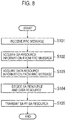
- Fig. 8 is a flowchart for describing an operation of the UE 100 according to an operation example 1.
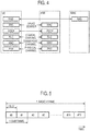
- Fig. 9 is a configuration diagram of a radio frame for describing the operation example 1.
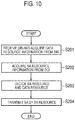
- Fig. 10 is a flowchart for describing an operation of the UE 100 according to a modification of the operation example 1.
- Fig. 11 is a flowchart for describing an operation of the UE 100 according to an operation example 2.
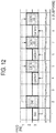
- Fig. 12 is a configuration diagram of a radio frame for describing the operation example 2.
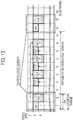
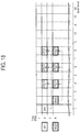
- Fig. 13 is a configuration diagram of a radio frame for describing a modification of the operation example 2.
- the UE 100 exists in a cell managed by the eNB 200.
- the eNB 200 transmits, to the UE 100, data resource information which is information for limiting a range of the data resource domain.
- the eNB 200 is capable of transmitting the data resource information to the UE 100 by at least either one of an RRC message (for example, an SIB (System Information Block)) or DCI (Downlink Control Information).
- the UE 100 decides a data resource on the basis of the data resource information received from the eNB 200.
- the data resource information is information for specifying a data resource domain, a data resource, or a candidate of the data resource domain. Furthermore, the data resource information may be information for limiting at least one of a position of the data resource and a size of the data resource.
- the data resource information includes information indicating at least any one of a frequency band and/or a time zone of the data resource domain, a period (time) of the data resource domain, an offset (time and/or frequency) from SA indicating a data resource start, and a data resource interval.
- the data resource information may include information indicating at least either one of a resource size of one data resource, the number of data resources, or a modulation and coding scheme (MCS) applied to the D2D communication data.
- MCS modulation and coding scheme
- the eNB 200 in the case of transmitting data resource information for (directly) specifying a data resource, the eNB 200 is capable of transmitting the data resource information by using DCI.
- the eNB 200 in the case of transmitting the data resource information for (directly) specifying a range of the data resource (that is, a data resource domain), the eNB 200 is capable of transmitting the data resource information by using an RRC message (for example, an SIB).
- the SA resource information is information for specifying an SA resource domain, an SA resource, or a candidate of the SA resource domain.
- the SA resource information includes information indicating at least any one of a frequency band and/or a time zone of the SA resource domain, an offset (time and/or frequency), and a period (time).
- offset SFN ⁇ 10 + subframe mod period
- the SA resource information may include information indicating at least any one of a size of one SA resource, the number of SA resources allocatable by the UE 100 (and/or the presence or absence of the SA resource), and a modulation and coding scheme (MCS) applied to the SA.
- MCS modulation and coding scheme
- the eNB 200 may transmit, as the SA resource information, information indicating the absence of the SA resource to the UE 100 or transmit, as the SA resource information, information indicating that the number of SA resources is 0, to the UE 100.
- step S101 the eNB 200 transmits by unicast, to the UE 100, the data resource information together with the SA resource information by an RRC message.
- the UE 100 receives the RRC message from the eNB 200.
- step S102 the UE 100 acquires the SA resource information from the RRC message. Furthermore, in step S103, the UE 100 acquires the data resource information from the RRC message.
- step S104 the UE 100 decides the SA resource and the data resource on the basis of the SA resource information and the data resource information.
- the SA resource information is an allocation rule for limiting the range of the SA resource domain
- the data resource information is an allocation rule for limiting the range of the data resource domain.
- the UE 100 decides the SA resource and the data resource from the SA resource domain and the data resource domains limited in range on the basis of these information.
- step S105 the UE 100 transmits SA 1 indicating the data resources of D2D communication data (DATA 11 to DATA 13) by using the SA resources, and transmits the DATA 11 to DATA 13 by using the data resources. Furthermore, the UE 100 transmits SA 2 indicating the data resources of D2D communication data (DATA 21 to DATA 23) by using the SA resources, and transmits DATA 21 to DATA 23.
- the eNB 200 transmits the data resource information by unicast. In the present modification, the eNB 200 transmits the data resource information by broadcast.
- the eNB 200 transmits the data resource information by an SIB.
- the UE 100 receives the SIB from the eNB 200 and acquires the data resource information from the SIB.
- the data resource information is an allocation rule for limiting the range of the data resource domain.
- step S202 the eNB 200 transmits the SA resource information by DCI.
- the UE 100 acquires the SA resource information from the DCI.
- a description will be provided on the assumption that the SA resource information is information for specifying the SA resources.
- step S203 the UE 100 decides data resources to be used from among data resource candidates on the basis of the SA resource information and the data resource information.
- the UE 100 may decide data resources on the further basis of a data capacity of the D2D communication data.
- the eNB 200 transmits SA resource information for specifying an SA resource indicating a position of SA 1.
- the UE 100 decides, as the SA resource, the SA resource (resource at a position of SA 1), which is specified from the eNB 200. Furthermore, the UE 100 decides data resources (resources at positions of DATA 11 to DATA 13) on the basis of the SA resource, the allocation rule for limiting the range of the data resource domain, and the data capacity.
- step S204 the UE 100 transmits SA 1 indicating the data resources of the D2D communication data (DATA 11 to DATA 13) by using the SA resource, and transmits DATA 11 to DATA 13 by using the data resources.
- the UE 100 decides SA resources on the basis of the SA resource information (resource at a position of SA 2) received from the eNB 200.
- the UE 100 decides data resources (resources at positions of DATA 21 to DATA 23) on the basis of the SA resources, the allocation rule for limiting the range of the data resources, and the data capacity.
- the UE 100 decides the data resources on the basis of the data resource information from the eNB 200.
- the UE 100 decides the data resources on the basis of setting information previously stored in the UE 100.
- the setting information is at least one of information for limiting the range of the data resource domain and information for limiting the range of the SA resource domain.
- the setting information may be the allocation rule for limiting the range of the data resource domain (and/or the allocation rule for limiting the range of the SA resource domain).
- the setting information has a configuration similar to that of the above-described data resource information (and/or the SA resource information).
- step S301 the UE 100-1 acquires the SA resource information from the DCI received from the eNB 200.
- a description will be provided on the assumption that the SA resource information indicates (subframe 1, RB 3: resource at a position of SA 1 in Fig. 12 ).
- step S302 the UE 100-1 decides the SA resource and the data resource on the basis of the SA resource information and the setting information.
- the SA resource information is (subframe 1, RB 3)
- the range of the control resource domain available for the UE 100 is limited.
- Step S303 corresponds to step S105.
- the UE 100-2 decides, as the SA resource, a resource at a position of SA 1. Furthermore, a description will be provided on the assumption that the UE 100-2 stores the same setting information as that of the UE 100-1.
- the UE 100 decides the data resources; however, the UE 100 may decide the data resources on the basis of the data resource information from the eNB 200.
- SA resource domains are provided periodically in a time axis direction in the time-frequency resources available for the D2D proximity service. Furthermore, in the modification of the operation example 2, the range of the SA resource domain in a next period is limited depending on the position of the SA resource in a previous period.
- the SA resource information indicates an allocation rule in which positions of SA resources are provided at the same positions as those of SA resources in a previous period.
- the data resource information indicates an allocation rule in which the range of the data resource domain is limited depending on the positions of the SA resources.
- the data resource information (or setting information) is the same information as the setting information of the above-described operation example 1.
- the UE 100-1 decides the resource at the position of SA 11 (subframe 11, RB 2) as the SA resource, since the position of the SA resource in a next period is provided at the same position as that of SA 11, the UE 100 decides the resource at the position of SA 12 (subframe 11, RB 2) as the SA resource.
- the UE 100-1 decides data resource depending on the position of the SA resource (subframe 11, RB 2) in a previous period.
- the UE 100-2 scans the SA resource domain before deciding the SA resource and when the UE 100-1 periodically continues to transmit SAs, the UE 100-2 is capable of avoiding the use of SA 11 in use on the basis of the SA resource information. As a consequence, it is possible to avoid a collision between the SA of the UE 100-1 and the SA of the other UE 100.
- Fig. 14 is a sequence for describing an operation of the mobile communication system according to the embodiment.
- Fig. 15 is a flowchart for describing an operation of the UE 100 located in coverage.
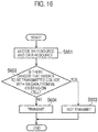
- Fig. 16 is a flowchart for describing an operation of the UE 100 located out of coverage.
- the UE 100 switches between the resource information and the setting information, and decides the SA resource and the data resource.
- the resource information is at least any one of the SA resource information and the data resource information. Details will be described, below.
- the eNB 200 broadcasts a predetermined radio signal.
- the predetermined radio signal is a synchronization signal (PSS: Primary Synchronization Signal/SSS: Secondary Synchronization Signal) or a cell reference signal (CRS: Cell Reference Signal), for example.
- PSS Primary Synchronization Signal/SSS: Secondary Synchronization Signal
- CRS Cell Reference Signal
- step S402 the UE 100 attempts decoding of the predetermined radio signal from the eNB 200.
- the process of step S403 is executed.
- the process of step S406 is executed.
- step S403 the UE 100 determines to be located out of coverage. It is noted that the UE 100 determines to be located out of coverage also when it is not possible to receive the radio signals from all eNBs 200 (that is, the reception level of the radio signals from all eNBs 200 is below a threshold value).
- step S404 in order to decide the SA resource and the data resource on the basis of the setting information, the UE 100 performs Pre-configure setting. In this way, when it is not possible to receive the resource information from the eNB 200, the UE 100 is capable of appropriately deciding the SA resource and the data resource. Thereafter, the UE 100 decides the SA resource and the data resource on the basis of the setting information (Pre-configure setting).
- the UE 100 uses the decided SA resource to transmit SA.
- the UE 100 may use the SA resource to transmit, together with the SA, flag information indicating whether or not the UE 100 is located out of coverage.
- the flag information indicates "1" when the UE 100 is located in coverage (in the case of In Coverage), and indicates "0" when the UE 100 is located out of coverage (in the case of Out of Coverage).
- the flag information indicates locating out of coverage.
- step S406 the UE 100 determines that the UE 100 exists in a cell of the eNB 200 from which the predetermined radio signal is transmitted.
- step S407 the eNB 200 transmits resource information (specifically, the SA resource information) to the UE 100.
- the UE 100 receives the resource information.
- step S408 in order to decide the SA resource and the data resource on the basis of the resource information received from the eNB 200, the UE 100 sets a setting value indicated by the SA resource information received from the eNB 200. Thereafter, the UE 100 decides the SA resource and the data resource on the basis of the SA resource (setting value). Thereafter, the UE 100 performs the process of step S405.
- the UE 100 may transmit, together with the SA, the flag information indicating that the UE 100 is not located out of coverage.
- step S501 the UE 100 scans the SA resource domain. Specifically, the UE 100 scans the SA resource domain limited in range on the basis of the SA resource information. The UE 100 uses an SA resource within the SA resource domain to receive the transmitted SA.
- the UE 100 determines whether or not the flag information indicates that another UE 100 which is the transmission source of the flag information is out of coverage. When the flag information indicates that the other UE 100 is out of coverage, the process of step S502 is executed. On the other hand, when the flag information indicates that the other UE 100 is not out of coverage, the UE 100 ends the process. It is noted that when the UE 100 receives a plurality of instances of flag information, the UE 100 ends the process only when each of the plurality of instances of the flag information indicates that the other UE 100 is not out of coverage. When any of the plurality of instances of the flag information indicates that the other UE 100 is out of coverage, the UE 100 executes the process of step S502.
- step S502 the UE 100 determines whether or not the UE 100 itself exists in a cell.
- the UE 100 for example, executes the processes of the above-described steps S402 to S404, and determines whether or not the UE 100 itself exists in the cell.
- the UE 100 executes the process of step S503.
- the UE 100 ends the process.
- the UE 100 transmits, to the other UE 100, the resource information (control resource information and/or data resource information) received from the cell in which the UE 100 exists.
- the UE 100 may notify the resource information by broadcast, or may transmit the resource information to the UE 100 located out of coverage by unicast.
- the UE 100 may use the SA resource to transmit the resource information, or may use the data resource to transmit the resource information.
- the UE 100 may transmit, together with the resource information, the flag information indicating that the UE 100 is not out of coverage.
- the other UE 100 located out of coverage is capable of receiving the resource information.
- the other UE 100 that receives the resource information is capable of performing the operation described below.
- step S601 the UE 100-2 decides the SA resource and the data resource.
- the UE 100-2 decides the SA resource and the data resource by prioritizing the data resource information over the setting information.
- the UE 100-2 may decide the SA resource and the data resource on the basis of the setting information.
- the UE 100-2 may decide the SA resource and the data resource on the basis of the resource information received from the UE 100-1.
- step S602 when the UE 100-2 determines that there is a danger of a collision between SA transmitted by using the SA resource decided in step S601 and SA and/or D2D communication data transmitted by the UE 100 existing in a cell (in the case of "Yes"), the UE 100-2 executes the process of step S603, and when the UE 100-2 determines that there is no danger of the collision (in the case of "No"), the UE 100-2 executes the process of step S604.
- the UE 100-2 determines that there is a danger of a collision between the D2D communication data transmitted by using the data resource decided in step S601 and the SA and/or the D2D communication data transmitted by the UE 100 existing in a cell (in the case of "Yes"), the UE 100-2 executes the process of step S603, and when the UE 100-2 determines that there is no danger of the collision (in the case of "No"), the UE 100-2 executes the process of step S604.
- the UE 100-2 scans the SA resource within the resource domain limited in range on the basis of the resource information from the UE 100-1 existing in a cell.
- the UE 100-2 grasps the SA resource used for transmitting the SA, and infers the SA resource used for transmitting the SA on the basis of the resource information.
- the UE 100-2 grasps the data resource indicated by the received SA.
- the UE 100-2 determines whether the inferred SA resource and the grasped data resource (resource of the UE 100 located in coverage) do not overlap the SA resource and the data resource used by the UE 100-2 to perform transmission (resource of the UE 100-2 itself).
- the UE 100-2 determines that the resource of the UE located in coverage overlaps the resource of the UE 100-2 itself, the UE 100-2 determines that there is a danger of a collision, and when the UE 100-2 determines that the resource of the UE located in coverage do not overlap the resource of the UE 100-2 itself, the UE 100-2 determines that there is no danger of a collision.
- the UE 100-2 may determine that there is no danger of a collision.
- the SA resource and the data resource of the UE 100-2 are within the range of the SA resource and/or the data resource of the UE 100 located in coverage, the UE 100-2 may determine that there is a danger of collision.
- step S603 the UE 100-2 does not transmit SA and D2D communication data by using the decided SA resource and the data resource.
- the UE 100-2 may newly decide the SA resource and the data resource on the basis of the resource information.
- step S604 the UE 100-2 transmits SA by using the decided SA resource, and transmits D2D communication data by using the decided data resource.
- the UE 100 decides a data resource and an SA resource from among time-frequency resources available for the D2D proximity service.
- the UE 100 decides the data resource from a data resource domain limited in range in the time-frequency resources available for the D2D proximity service.
- the UE 100 for example, is capable of avoiding selection of a data resource domain from an area different from the data resource domain (for example, SA resource domains), thereby appropriately deciding the data resource.
- the eNB 200 transmits data resource information to the UE 100.
- the UE 100 when the UE 100 exists in a cell managed by the eNB 200, the UE 100 takes an initiative in deciding the SA resource and a data resource; however, the eNB 200 may control the decision of an SA resource and a data resource.
- an SA resource and a data resource domain are decided by the initiative of the UE 100, and thus, there is a merit that the operation of the UE 100 is not complicated.
- the eNB 200 transmits, together with SA resource information, data resource information to the UE 100 by unicast. In this way, on the basis of both the SA resource information and the data resource information, the UE 100 is capable of appropriately deciding the SA resource and the data resource.
- the UE 100 transmits the data resource information by broadcast.
- the data resource information is information for limiting at least one of the position of a data resource and the size of a data resource.
- the eNB 200 is capable of appropriately controlling the decision by the UE 100 existing in a cell about an SA resource and a data resource.
- the UE 100 when the UE 100 exists in a cell managed by the eNB 200, the UE 100 transmits data resource information received from the eNB 200. In this way, a UE 100 located out of coverage is capable of deciding the SA resource and the data resource on the basis of the data resource information received from the UE 100 existing in a cell.
- the UE 100 when the UE 100 receives, from another UE 100, flag information indicating that the other UE 100 is located out of coverage, the UE 100 transmits the data resource information to the other UE 100. In this way, since the UE 100 confirms that the other UE 100 is located out of coverage and then transmits the data resource information, it is possible to suppress unnecessary transmission of the data resource information.
- the UE 100 located out of coverage when the UE 100 located out of coverage receives the data resource information from the UE 100, the UE 100 located out of coverage prioritizes the data resource information over the setting information to decide the data resource. In this way, when D2D communication is performed around a cell edge, it is possible to reduce a collision between SA and/or D2D communication data of the UE 100 located out of coverage and SA and/or D2D communication data of the UE 100 existing in a cell.
- the UE 100 decides the data resource on the basis of the position of an SA resource and/or the size of an SA resource.
- the eNB 200 is capable of controlling the decision of a data resource by the SA resource information without transmitting the data resource information.
- the SA resource domain is provided periodically in a time axis direction.
- the range of an SA resource domain in a next period is limited.
- the range of the data resource domain is limited.
- the UE 100 decides the data resource depending on the position of the SA resource in a previous period. In this way, since the range of the data resource domain is limited depending on the position of the SA resource, when SA resources respectively used by the UE 100 and another UE 100 do not overlap each other, it is possible to avoid a collision of the respective data resources of the UE 100 and the other UE 100.
- the range of the SA resource domain in a next period is limited depending on the position of the SA resource in a previous period, it is possible to avoid the use of the SA resource in a next period corresponding to the position of the SA resource that is being used in a previous period. Therefore, it is possible to avoid collisions of the respective SAs of the UE 100 and the other UE 100.
- the UE 100 is capable of using an SA resource to transmit, together with SAs, flag information indicating whether or not the UE 100 is located out of coverage. In this way, another UE 100 is capable of scanning an SA resource domain, thereby grasping whether or not a UE 100 located out of coverage exists around the other UE 100.
- the UE 100 may transmit, to another UE 100, resource information received from the cell in which the UE 100 exists. For example, when a reception level of a radio signal from the eNB 200 is within a predetermined range, the UE 100 determines that the UE 100 is located at the edge of a cell. Alternatively, the UE 100 may determine whether the UE 100 is located at the edge of a cell by GNSS information.
- the UE 100 may repeatedly transmit the same D2D communication data at a bit level by using the decided data resource. Specifically, when the decided data resource is configured by a plurality of data channel elements, the UE 100 transmits the same D2D communication data through each of the plurality of data channel elements.
- the UE 100 may reduce a bit number of data with a high priority (for example, emergency data), and repeatedly transmit the data with a high priority in one data resource (resource block). For example, in the case of utilizing VoIP as an application used in D2D communication, the UE 100 may repeatedly transmit voice data with an increased compression rate in one resource block.
- a high priority for example, emergency data
- VoIP as an application used in D2D communication
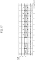
- Fig. 17 is a configuration diagram of a radio frame in the mobile communication system according to another embodiment.
- SA 1a and SA 1b have the same information and indicate the positions of the same data resources.
- Each of SA 1a and SA 1b indicates the positions of data resources of DATA 11a to DATA 13b.
- DATA 11a and DATA 11b are the same D2D communication data
- DATA 12a and DATA 12b are the same D2D communication data
- DATA 13a and DATA 13b are the same D2D communication data.
- the UE 100 repeatedly transmits the same D2D communication data in units of resource blocks in a time axis direction; however, the present invention is not limited thereto.
- the UE 100 may repeatedly transmit the same D2D communication data in units of resource blocks in a frequency axis direction.
- the eNB 200 in the case of transmitting SA resource information for (directly) specifying an SA resource, the eNB 200 is capable of transmitting the SA resource information by using DCI.
- the eNB 200 in the case of transmitting SA resource information for (directly) specifying the range of an SA resource (that is, SA resource domain), the eNB 200 is capable of transmitting the SA resource information by using an RRC message (for example, an SIB).
- the present invention is not limited to the LTE system, and may also be applied to systems other than the LTE system.
- SA assisted resource allocation provides a possibility of efficient collision avoidance.
- SA has several advantages.
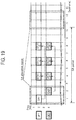
- Fig. 18 shows a method by which a UE 2 detects SA 1 transmitted by a UE 1, and schedules data transmission of the UE 2 by using the detected information to avoid resources listed in SA 1. Moreover, in order to improve the above-mentioned resource allocation, an additional operation related to SA based on a resource allocation scheme will be proposed.
- SA transmissions are periodic and using pre-defined time-frequency resources known to the receiver.
- the location for SA transmission resources can be grouped together within a region for simpler detection.
- Proposal 1 If SA is agreed then SAs should be transmitted periodically and grouped together within a given region.
- Each SA is mapped to a certain set of time-frequency resources that can be used for data transmissions.
- Each D2D is allowed to select a resource for its SA transmission as described in the above section.
- the same D2D UE can only transmit its data in resources that are associated with the SA resource location.
- the location of the SA determines the location of the data transmission resources.
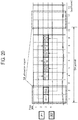
- SA1 and SA2 points to data 11, 12, 13 and data 21, 22, 23 respectively. This method avoids collisions between data transmissions.
- Proposal 2 In order to avoid data collisions SA is mapped to a certain set of time-frequency resources that can be used for data transmissions.
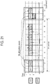
- Each D2D UE monitors the SA region to detect SA transmitted by the other D2D UEs. Using this information, the same D2D UE avoids transmitting its SA in the same resource used by other D2D UEs during the previous SA transmissions. For example, as shown in figure 21 , UE1 and UE2 transmit SA11 and SA21 respectively. A third D2D UE (not shown in the figure) detects those transmissions and then transmits its SA32 at a different location. UE1 and UE2 can use the same resources used in the previous iteration for SA12 and SA22, respectively. In the initial first SA period UE1 and UE2 can randomly select resources for SA transmissions.
- Proposal 3 If SA is agreed then to reduce SA collisions, D2D UE avoids transmitting its SA in the same resource used by the other D2D UEs in the previous SA transmissions.
- Proposal 4 If SA is agreed, then the resources for the initial SA transmissions are randomly selected in the SA region.
- a mobile communication system and a user terminal according to the present embodiment are useful in the mobile communication field, since the user terminal is capable of appropriately deciding a data resource used for transmitting D2D communication data.
Landscapes
- Engineering & Computer Science (AREA)
- Computer Networks & Wireless Communication (AREA)
- Signal Processing (AREA)
- Mobile Radio Communication Systems (AREA)
Applications Claiming Priority (2)
| Application Number | Priority Date | Filing Date | Title |
|---|---|---|---|
| US201461934336P | 2014-01-31 | 2014-01-31 | |
| PCT/JP2015/052414 WO2015115506A1 (ja) | 2014-01-31 | 2015-01-28 | 移動通信システム及びユーザ端末 |
Publications (2)
| Publication Number | Publication Date |
|---|---|
| EP3101977A1 true EP3101977A1 (de) | 2016-12-07 |
| EP3101977A4 EP3101977A4 (de) | 2017-09-20 |
Family
ID=53757078
Family Applications (1)
| Application Number | Title | Priority Date | Filing Date |
|---|---|---|---|
| EP15744019.9A Withdrawn EP3101977A4 (de) | 2014-01-31 | 2015-01-28 | Mobilkommunikationssystem und benutzerendgerät |
Country Status (4)
| Country | Link |
|---|---|
| US (2) | US10212696B2 (de) |
| EP (1) | EP3101977A4 (de) |
| JP (3) | JP6077680B2 (de) |
| WO (1) | WO2015115506A1 (de) |
Families Citing this family (9)
| Publication number | Priority date | Publication date | Assignee | Title |
|---|---|---|---|---|
| US10313831B2 (en) * | 2014-05-09 | 2019-06-04 | Futurewei Technologies, Inc. | Extensible solution for device to device discovery message size |
| US10667249B2 (en) * | 2014-06-24 | 2020-05-26 | Lg Electronics Inc. | Resource allocation method for communication between transceiving terminals in communication system supporting device to device communication, and apparatus therefor |
| KR102091476B1 (ko) * | 2014-10-20 | 2020-03-24 | 아이피컴 게엠베하 앤 코. 카게 | 통신 네트워크에서의 리소스 관리를 위한 리소스 컨트롤러 |
| JP6593531B2 (ja) | 2015-10-26 | 2019-10-23 | 富士通株式会社 | 無線通信システムにおいて使用される基地局および無線装置 |
| JP7209456B2 (ja) * | 2016-08-08 | 2023-01-20 | ソニーグループ株式会社 | 基地局装置、端末装置、通信方法、及びプログラム |
| CN111886916A (zh) * | 2018-03-16 | 2020-11-03 | 瑞典爱立信有限公司 | 用于设备到设备通信的技术 |
| JP7401515B2 (ja) | 2018-07-05 | 2023-12-19 | オッポ広東移動通信有限公司 | 車両ネットワークにおけるデータ伝送方法及び端末デバイス |
| EP3800954B1 (de) | 2018-07-05 | 2026-04-29 | Guangdong Oppo Mobile Telecommunications Corp., Ltd. | Verfahren zur trägerauswahl im internet der fahrzeuge und endgerätevorrichtung |
| EP3700109B1 (de) * | 2019-02-21 | 2024-01-10 | Volkswagen Aktiengesellschaft | Fahrzeug, system, vorrichtungen, verfahren und computerprogramme für benutzergerät und eine netzwerkkomponente eines mobilkommunikationssystems |
Family Cites Families (13)
| Publication number | Priority date | Publication date | Assignee | Title |
|---|---|---|---|---|
| CN1735256A (zh) * | 2004-08-10 | 2006-02-15 | 皇家飞利浦电子股份有限公司 | 一种动态频率重用方法及装置 |
| JP5387010B2 (ja) * | 2009-01-28 | 2014-01-15 | 日本電気株式会社 | ユーザ行動監視システム及びユーザ行動監視方法 |
| KR101169285B1 (ko) * | 2011-12-08 | 2012-08-02 | 엘지전자 주식회사 | 지속적 스케줄링 정보를 전송 및 수신하는 방법 및 이를 위한 장치 |
| KR20130065002A (ko) * | 2011-12-09 | 2013-06-19 | 한국전자통신연구원 | 단말간 직접 통신 제어 방법 |
| KR102081937B1 (ko) * | 2012-02-14 | 2020-02-26 | 엘지전자 주식회사 | 장치 대 장치 통신 방법 및 이를 수행하기 위한 장치 |
| JP5939299B2 (ja) * | 2012-05-31 | 2016-06-22 | 富士通株式会社 | 無線通信システム、無線基地局装置、端末装置、及び無線リソースの割り当て方法 |
| EP2861027A4 (de) | 2012-06-06 | 2016-01-20 | Kyocera Corp | Kommunikationssteuerungsverfahren und basisstation |
| WO2013191518A1 (ko) * | 2012-06-22 | 2013-12-27 | 엘지전자 주식회사 | 기기-대-기기 통신을 위한 스케줄링 방법 및 이를 위한 장치 |
| WO2014017476A1 (ja) * | 2012-07-27 | 2014-01-30 | 京セラ株式会社 | 移動通信システム、基地局、ユーザ端末、及びプロセッサ |
| WO2014017498A1 (ja) * | 2012-07-27 | 2014-01-30 | 京セラ株式会社 | 移動通信システム |
| US8982895B2 (en) * | 2012-09-21 | 2015-03-17 | Blackberry Limited | Inter-device communication in wireless communication systems |
| EP3050393B1 (de) * | 2013-09-27 | 2019-12-04 | Telefonaktiebolaget LM Ericsson (publ) | Weiterleitung von d2d-steuerinformationen |
| WO2015065112A1 (ko) * | 2013-10-31 | 2015-05-07 | 엘지전자(주) | 무선 통신 시스템에서 디스커버리 메시지를 전송하는 방법 및 이를 위한 장치 |
-
2015
- 2015-01-28 EP EP15744019.9A patent/EP3101977A4/de not_active Withdrawn
- 2015-01-28 JP JP2015559991A patent/JP6077680B2/ja not_active Expired - Fee Related
- 2015-01-28 WO PCT/JP2015/052414 patent/WO2015115506A1/ja not_active Ceased
-
2016
- 2016-07-29 US US15/223,573 patent/US10212696B2/en active Active
-
2017
- 2017-01-12 JP JP2017003267A patent/JP6313485B2/ja not_active Expired - Fee Related
-
2018
- 2018-03-22 JP JP2018054857A patent/JP2018137775A/ja active Pending
- 2018-12-18 US US16/224,680 patent/US20190124641A1/en not_active Abandoned
Also Published As
| Publication number | Publication date |
|---|---|
| US20190124641A1 (en) | 2019-04-25 |
| JP6313485B2 (ja) | 2018-04-18 |
| WO2015115506A1 (ja) | 2015-08-06 |
| JP6077680B2 (ja) | 2017-02-08 |
| EP3101977A4 (de) | 2017-09-20 |
| US20160338035A1 (en) | 2016-11-17 |
| JP2017085650A (ja) | 2017-05-18 |
| US10212696B2 (en) | 2019-02-19 |
| JP2018137775A (ja) | 2018-08-30 |
| JPWO2015115506A1 (ja) | 2017-03-23 |
Similar Documents
| Publication | Publication Date | Title |
|---|---|---|
| EP3101973B1 (de) | Mobilkommunikationssystem und benutzerendgerät | |
| US10813152B2 (en) | User terminal, processor, and base station | |
| US10098162B2 (en) | Mobile communication system, user terminal, base station, processor, and communication control method | |
| US10212696B2 (en) | Mobile communication system and user terminal | |
| EP2879414A1 (de) | Mobilkommunikationssystem, basisstation, benutzervorrichtung und prozessor | |
| EP2961240A1 (de) | Mobiles kommunikationssystem, basisstation, benutzerendgeräte und prozessor | |
| US10750480B2 (en) | Mobile communication system, user terminal, base station, processor, and communication control method | |
| EP2903393A1 (de) | Mobilkommunikationssystem, basisstation und benutzerendgerät | |
| US10070420B2 (en) | Mobile communication system and user terminal | |
| US9923689B2 (en) | Mobile communication system, user terminal, and processor for assigning radio resources for transmission of sounding reference signals and device to device communication resources | |
| US9924496B2 (en) | Network apparatus and user terminal | |
| EP2996384A1 (de) | Kommunikationssteuerungsverfahren, benutzerendgerät und prozessor | |
| EP3079441A1 (de) | Kommunikationssteuerungsverfahren, benutzergerät und basisstation |
Legal Events
| Date | Code | Title | Description |
|---|---|---|---|
| PUAI | Public reference made under article 153(3) epc to a published international application that has entered the european phase |
Free format text: ORIGINAL CODE: 0009012 |
|
| 17P | Request for examination filed |
Effective date: 20160728 |
|
| AK | Designated contracting states |
Kind code of ref document: A1 Designated state(s): AL AT BE BG CH CY CZ DE DK EE ES FI FR GB GR HR HU IE IS IT LI LT LU LV MC MK MT NL NO PL PT RO RS SE SI SK SM TR |
|
| AX | Request for extension of the european patent |
Extension state: BA ME |
|
| DAX | Request for extension of the european patent (deleted) | ||
| A4 | Supplementary search report drawn up and despatched |
Effective date: 20170818 |
|
| RIC1 | Information provided on ipc code assigned before grant |
Ipc: H04W 8/00 20090101ALN20170811BHEP Ipc: H04W 76/02 20090101AFI20170811BHEP |
|
| 17Q | First examination report despatched |
Effective date: 20190430 |
|
| STAA | Information on the status of an ep patent application or granted ep patent |
Free format text: STATUS: THE APPLICATION HAS BEEN WITHDRAWN |
|
| 18W | Application withdrawn |
Effective date: 20190730 |