EP3101982A1 - Basisstation, übertragungsverfahren, mobilstation und rückübertragungssteuerungsverfahren - Google Patents
Basisstation, übertragungsverfahren, mobilstation und rückübertragungssteuerungsverfahren Download PDFInfo
- Publication number
- EP3101982A1 EP3101982A1 EP14880523.7A EP14880523A EP3101982A1 EP 3101982 A1 EP3101982 A1 EP 3101982A1 EP 14880523 A EP14880523 A EP 14880523A EP 3101982 A1 EP3101982 A1 EP 3101982A1
- Authority
- EP
- European Patent Office
- Prior art keywords
- physical downlink
- control channel
- resource
- pucch
- assignment information
- Prior art date
- Legal status (The legal status is an assumption and is not a legal conclusion. Google has not performed a legal analysis and makes no representation as to the accuracy of the status listed.)
- Withdrawn
Links
Images







Classifications
-
- H—ELECTRICITY
- H04—ELECTRIC COMMUNICATION TECHNIQUE
- H04L—TRANSMISSION OF DIGITAL INFORMATION, e.g. TELEGRAPHIC COMMUNICATION
- H04L5/00—Arrangements affording multiple use of the transmission path
- H04L5/003—Arrangements for allocating sub-channels of the transmission path
- H04L5/0053—Allocation of signalling, i.e. of overhead other than pilot signals
-
- H—ELECTRICITY
- H04—ELECTRIC COMMUNICATION TECHNIQUE
- H04W—WIRELESS COMMUNICATION NETWORKS
- H04W72/00—Local resource management
- H04W72/50—Allocation or scheduling criteria for wireless resources
- H04W72/51—Allocation or scheduling criteria for wireless resources based on terminal or device properties
-
- H—ELECTRICITY
- H04—ELECTRIC COMMUNICATION TECHNIQUE
- H04L—TRANSMISSION OF DIGITAL INFORMATION, e.g. TELEGRAPHIC COMMUNICATION
- H04L5/00—Arrangements affording multiple use of the transmission path
- H04L5/003—Arrangements for allocating sub-channels of the transmission path
- H04L5/0053—Allocation of signalling, i.e. of overhead other than pilot signals
- H04L5/0055—Physical resource allocation for ACK/NACK
-
- H—ELECTRICITY
- H04—ELECTRIC COMMUNICATION TECHNIQUE
- H04L—TRANSMISSION OF DIGITAL INFORMATION, e.g. TELEGRAPHIC COMMUNICATION
- H04L5/00—Arrangements affording multiple use of the transmission path
- H04L5/0091—Signalling for the administration of the divided path, e.g. signalling of configuration information
- H04L5/0094—Indication of how sub-channels of the path are allocated
-
- H—ELECTRICITY
- H04—ELECTRIC COMMUNICATION TECHNIQUE
- H04W—WIRELESS COMMUNICATION NETWORKS
- H04W4/00—Services specially adapted for wireless communication networks; Facilities therefor
- H04W4/70—Services for machine-to-machine communication [M2M] or machine type communication [MTC]
-
- H—ELECTRICITY
- H04—ELECTRIC COMMUNICATION TECHNIQUE
- H04W—WIRELESS COMMUNICATION NETWORKS
- H04W72/00—Local resource management
- H04W72/20—Control channels or signalling for resource management
-
- H—ELECTRICITY
- H04—ELECTRIC COMMUNICATION TECHNIQUE
- H04W—WIRELESS COMMUNICATION NETWORKS
- H04W72/00—Local resource management
- H04W72/20—Control channels or signalling for resource management
- H04W72/21—Control channels or signalling for resource management in the uplink direction of a wireless link, i.e. towards the network
-
- H—ELECTRICITY
- H04—ELECTRIC COMMUNICATION TECHNIQUE
- H04W—WIRELESS COMMUNICATION NETWORKS
- H04W72/00—Local resource management
- H04W72/20—Control channels or signalling for resource management
- H04W72/23—Control channels or signalling for resource management in the downlink direction of a wireless link, i.e. towards a terminal
-
- H—ELECTRICITY
- H04—ELECTRIC COMMUNICATION TECHNIQUE
- H04L—TRANSMISSION OF DIGITAL INFORMATION, e.g. TELEGRAPHIC COMMUNICATION
- H04L5/00—Arrangements affording multiple use of the transmission path
- H04L5/003—Arrangements for allocating sub-channels of the transmission path
- H04L5/0078—Timing of allocation
- H04L5/0082—Timing of allocation at predetermined intervals
Definitions
- the present invention relates to a base station, a transmission method, a mobile station and a retransmission control method.
- the MTC terminal is a power meter, a gas meter, a vending machine, a vehicle and any other communication terminals installed in industrial equipment and so on.
- Some specifications for such a MTC terminal different from those for a normal terminal (UE: User Equipment) are discussed due to characteristics of non-mobility, periodic transmission of a small amount of data and so on (see 3GPP TR36.888 V12.0.0 (2013-06 )).
- the MTC terminals In light of the above-stated usage implementations, for the MTC terminals, some techniques to achieve low-cost MTC terminals are required. Also, it is considered that the MTC terminals may be used at locations where propagation loss is significantly large, such as within an indoor control box. Accordingly, there is a need of some techniques to enhance coverage of the MTC terminals.
- the low cost mode is a mode designed to lower the cost of the MTC terminals.
- the low cost mode of MTC terminals it is designed to downsize a buffer in the MTC terminal by reducing a transmission data rate or decreasing a reception bandwidth of a base band of data signals.
- two antennas are provided in a normal terminal whereas a single antenna is provided in the MTC terminals to lower the cost.
- the enhanced coverage mode is a mode to enhance the coverage of the MTC terminal.
- Various functions to improve communication quality are provided in the enhanced coverage mode of MTC terminals.
- a PDSCH Physical Downlink Shared Channel
- a PDCCH Physical Downlink Control Channel
- assignment information DL assignment
- the PDSCH and the PDCCH are transmitted in different subframes.
- the PDCCH and the PDSCH are iteratively transmitted in different subframes for the enhanced coverage mode of MTC terminals so as to improve reception quality of the MTC terminals.
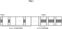
- FIG. 1 illustrates a relationship between the PDCCH and the PDSCH in the enhanced coverage mode.
- a relationship between the PDCCH and the PDSCH of indication timings of the assignment information in the enhanced coverage mode is predefined, and as illustrated in FIG. 1 , the PDCCH and the PDSCH are not transmitted in the same subframe but the PDSCH is transmitted in multiple subframes after the PDCCH is transmitted in multiple subframes. Specifically, assuming that the last subframe for transmitting the PDCCH is the n-th subframe, transmission of the PDSCH starts from the (n+k)-th subframe (k>0). In the low cost mode, on the other hand, such iterative transmissions are not typically performed, and after the PDCCH is transmitted in a certain subframe, the PDSCH is transmitted in other subframes.
- acknowledgement information is transmitted in a PUCCH (Physical Uplink Control Channel).
- PUCCH resources are assigned in accordance with formula (1) as follows (see 3GPP TS36.213 V12.0.0 (2013-12 )).
- n PUCCH n CCE +N PUCCH (1), where n PUCCH is a number for representing the PUCCH resource, n CCE is the first CCE (Control Channel Element) index of the PDCCH corresponding to the PUCCH, and N PUCCH is an index configured in upper layer signaling.
- the PUCCH resource is calculated from an assignment position of the PDCCH resource.
- a terminal After a constant time period (for example, after 4 ms) of receiving the PDSCH, a terminal uses a resource found by formula (1) to transmit the PUCCH.
- Formula (1) derives the PUCCH resource under assumption where the PDCCH and the PDSCH are transmitted in the same subframe. Accordingly, if the PDCCH and the PDSCH are transmitted in different subframes, there is a possibility where there may arise conflict of the PUCCH resource among terminals.
- Such conflict of the PUCCH resource arises under the case where there are a mixture of users having different relationships between subframes for transmitting the PDCCH and subframes for transmitting the PDSCH.
- the PDCCH and the PDSCH are iteratively transmitted such as the case for the enhanced coverage mode of MTC terminals, it is expected that the conflicting probability of the PUCCH resources may further increase.
- An object of the present invention is to avoid or reduce the PUCCH conflict among terminals under the case where the PDSCH and the PDCCH for indicating assignment information required to receive the PDSCH are transmitted in different subframes.
- a base station transmits a physical downlink shared channel and a physical downlink control channel in different subframes, wherein the physical downlink control channel indicates assignment information required to receive the physical downlink shared channel, and includes:
- a transmission method is used in a base station for transmitting a physical downlink shared channel and a physical downlink control channel in different subframes, wherein the physical downlink control channel indicates assignment information required to receive the physical downlink shared channel, and includes:
- a mobile station receives a physical downlink shared channel and a physical downlink control channel in different subframes, wherein the physical downlink control channel indicates assignment information required to receive the physical downlink shared channel, and includes:
- a retransmission control method is used in a mobile station for receiving a physical downlink shared channel and a physical downlink control channel in different subframes, wherein the physical downlink control channel indicates assignment information required to receive the physical downlink shared channel, and includes:
- a base station transmits a physical downlink shared channel and a physical downlink control channel in different subframes, wherein the physical downlink control channel indicates assignment information required to receive the physical downlink shared channel, and includes:
- a transmission method is used in a base station for transmitting a physical downlink shared channel and a physical downlink control channel in different subframes, wherein the physical downlink control channel indicates assignment information required to receive the physical downlink shared channel, and includes:
- a mobile station receives a physical downlink shared channel and a physical downlink control channel in different subframes, wherein the physical downlink control channel indicates assignment information required to receive the physical downlink shared channel, and includes:
- a retransmission control method is used in a mobile station for receiving a physical downlink shared channel and a physical downlink control channel in different subframes, wherein the physical downlink control channel indicates assignment information required to receive the physical downlink shared channel, and includes:
- the PUCCH conflict among terminals can be avoided or reduced under the case where the PDSCH and the PDCCH for indicating assignment information required to receive the PDSCH are transmitted in different subframes.
- some approaches for avoiding PUCCH conflict among terminals are described in cases where terminals receiving a PDCCH and a PDSCH in different subframes such as MTC terminals exist.
- the terminal may be also referred to as a mobile station or user equipment (UE).
- UE user equipment
- the terminal receiving the PDCCH and the PDSCH in different subframes is referred to as a MTC terminal, and the terminal receiving the PDCCH and the PDSCH in the same subframe is referred to as a LTE terminal.
- the PDCCH and the (E)PDCCH are collectively referred to as the PDCCH below.
- the enhanced coverage mode of the MTC terminal is illustratively described below, but the present invention is not limited to it and can be also applied to the low cost mode. In other words, it can be easily understood that the case where the number of iterations is equal to 1 in the enhanced coverage mode corresponds to the low cost mode.
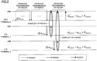
- FIG. 2 is a diagram for illustrating the PUCCH conflict due to iterative transmissions of the PUCCH by MTC terminals.
- the PDCCH and the PDSCH are iteratively transmitted to the enhanced coverage mode of MTC terminals so as to expand the coverage of the MTC terminals.
- a HARQ Hybrid ARQ
- a HARQ feedback including acknowledgement information (ACK/NACK) is transmitted in a PUCCH.
- the PUCCH is iteratively transmitted corresponding to iterative transmissions of the PDSCH. Note that there is a case where only any one of the PDCCH, the PDSCH and PUCCH is iteratively transmitted.
- the PUCCH is transmitted after a constant time period (for example, after 4ms) from completion of iterative transmissions of the PDSCH.
- n CCEi is the first CCE index of the PDCCH corresponding to the PUCCH, and for the MTC terminal 0, CCE index n CCEi for use in iterative transmission of the PDCCH before several frames is used.
- a normal LTE terminal also exists in the same coverage and communicates with the same base station (eNB: enhanced Node B) as the MTC terminal.
- the LTE terminal transmits the PUCCH after a constant time period (for example, 4 ms) from receiving the PDCCH and the PDSCH transmitted in the same frame.
- n CCEi is the first CCE index of the PDCCH corresponding to the PUCCH, and for the LTE terminal 1, the CCE index n CCEi for use in the PDCCH in the subframe before 4 ms in FDD (Frequency Division Duplex) is used, for example.
- n CCEi of the MTC terminal 0 may be equal to n CCEi of the LTE terminal 1, and in this case, the PUCCH conflict may arise.
- the PUCCH conflict with LTE terminal 2 may arise during iterative transmissions of the PUCCH by the MTC terminal 0.
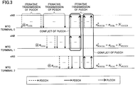
- FIG. 3 is a diagram for illustrating the PUCCH conflict due to iterative transmissions of the PUCCH from MTC terminals.
- the PUCCH conflict in the case where MTC terminals iteratively transmit the PUCCH is illustrated.
- the number of PUCCH transmissions by the enhanced coverage mode of MTC terminals increases, and the probability of the PUCCH conflict would be higher than the case in FIG. 2 .
- the PUCCH conflict due to iterative transmissions of the PUCCH by the MTC terminal is illustrated, but this PUCCH conflict may arise in not only the case where the PUCCH is iteratively transmitted but also the case where there is a mixture of users having different transmission timings of the PDCCH and the PDSCH.
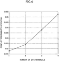
- FIG. 4 illustrates a PUCCH conflict probability.
- FIG. 4 illustrates simulation results in the case where 16 terminals exist in the same coverage and the PDCCH, the PDSCH and the PUCCH are transmitted with the same number of iterations (ten times). The greater the number of MTC terminals is, the higher the PUCCH conflict probability is.
- a PDCCH resource is assigned at a base station to prevent the PUCCH conflict.
- the PUCCH resource is derived from an assignment position (n CCEi ) of the PDCCH resource and a start index (N PUCCH ) of the PUCCH resource configured by upper layer signaling.
- the base station assigns the PDCCH resource in consideration of previous PDCCH resource assignment information such that the same n CCE cannot be used among PDCCHs using the same subframe for transmitting a HARQ feedback.
- the PDCCH resource is assigned in consideration of assignment information of reserved PUCCH resources such that the same resource cannot be redundantly assigned in the same subframe for PUCCHs for different terminals.
- the base station configures the N PUCCH specific to a MTC terminal and assigns a PUCCH resource such that the same resource cannot be redundantly assigned in the same subframe for PUCCHs for different terminals.
- a MTC terminal performs retransmission determination for a PDSCH, and if the retransmission is not needed, the MTC terminal does not transmit an ACK, and otherwise if the retransmission is needed, the MTC terminal transmits a NACK. In other words, only the NACK of acknowledgement information (ACK/NACK) is transmitted. Since the MTC terminal having better reception environment does not transmit the PUCCH, the PUCCH conflict will be reduced.
- a base station indicates a PUCCH resource to be used by a MTC terminal explicitly or implicitly.
- the base station signals multiple candidates of the PUCCH resource to the terminal beforehand.
- the base station determines the PUCCH resource to be used by the MTC terminal from the indicated multiple PUCCH resource candidates and transmits an indicator (ARI: ACK Indicator field) for determining the PUCCH resource to indicate explicitly.
- the MTC terminal receives the indicator for determining the PUCCH resource and transmits the PUCCH in accordance with the received indicator.
- the base station may indicate the PUCCH resource to be used by the MTC terminal to the MTC terminal in an implicit indication where an indicated offset is added to the above-stated formula (1).
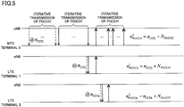
- FIG. 5 illustrates that the PUCCH conflict is avoided in accordance with the first approach of an embodiment of the present invention.
- the base station recognizes to which resources the PDCCH have been assigned (PDCCH resource assignment information) and as a result, recognizes in which resources the PUCCH will be received (PUCCH resource assignment information).
- the base station uses the PDCCH resource assignment information or the PUCCH resource assignment information to assign PDCCH resources such that the PUCCH conflict cannot arise. For example, it is assumed that the PDCCH and the PDSCH are assigned to multiple subframes for the MTC terminal and the MTC terminal receives the PUCCH in the multiple subframes. Then, if a LTE terminal communicates, PDCCH resources are assigned for the LTE terminal such that the PUCCH can be transmitted in a resource different from the PUCCH transmitted by the MTC terminal.
- FIG. 6 illustrates that the PUCCH conflict is avoided in the case where multiple MTC terminals are communicating. Also in this case, as in the description in conjunction with FIG. 5 , a base station uses the PDCCH resource assignment information or the PUCCH resource assignment information to assign PDCCH resources such that the PUCCH conflict cannot arise.
- a PDCCH resource indicated by different N PUCCH is assigned for a LTE terminal such that the same N PUCCH cannot be used in subframes for the MTC terminal to transmit the PUCCH.
- the N PUCCH may be set to a value specific to the MTC terminal.
- values (N PUCCH LowcostMCE , N PUCCH enhancedcoverageMCE ) specific to a mode type may be set to N PUCCH .
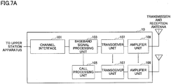
- FIG. 7A is a structural diagram of a base station (eNB) 10 according to an embodiment of the present invention.
- the base station 10 has a channel interface 101, a baseband signal processing unit 103, a call processing unit 105, a transceiver unit 107 and an amplifier unit 109.
- Data transmitted from the base station 10 to a mobile station in a downlink is supplied from an upper station device to the baseband signal processing unit 103 via the channel interface 101.
- the baseband signal processing unit 103 performs a PDCP (Packet Data Convergence Protocol) layer operation, data segmentation and concatenation, a RLC (Radio Link Control) layer transmission operation such as a transmission operation for RLC retransmission control, a MAC (Medium Access Control) retransmission control such as a HARQ (Hybrid Automatic Repeat request) transmission operation, scheduling, transmission format selection, channel encoding, an IFFT (Inverse Fast Fourier Transform) operation and a precoding operation. Also, transmission operations such as channel encoding and Inverse Fast Fourier Transform are performed on PDCCH signals serving as a downlink control channel.
- PDCP Packet Data Convergence Protocol
- RLC Radio Link Control
- MAC Medium Access Control
- HARQ Hybrid Automatic Repeat request
- transmission operations such as channel encoding and Inverse Fast Fourier Transform are performed on PDCCH signals serving as a downlink control channel.
- the call processing unit 105 performs call operations such as configuring or releasing a communication channel, state management for the base station 10 and radio resource management.
- the transceiver unit 107 performs frequency conversion on a baseband signal supplied from the baseband signal processing unit 103 into a radio frequency band.
- the amplifier unit 109 amplifies the frequency-converted transmission signal and supplies it to a transmission and reception antenna. If multiple transmission and reception antennas are used, the multiple transceiver units 107 and amplifier units 109 may be provided.
- a radio frequency signal received at the transmission and reception antenna is amplified at the amplifier unit 109 and frequency-converted at the transceiver unit 107 into a baseband signal, which is supplied to the baseband signal processing unit 103.
- the baseband signal processing unit 103 performs a FFT operation, an IDFT operation, error correction decoding, a reception operation for MAC retransmission control, a RLC layer reception operation and a PDCP layer reception operation on data included in the baseband signal received in the uplink.
- the decoded signal is forwarded to the upper station device via the channel interface 101.
- FIG. 7B is a structural diagram of the baseband signal processing unit 103 in the base station 10 according to an embodiment of the present invention.
- the baseband signal processing unit 103 has a control unit 1031, a downlink (DL) signal generation unit 1032, a mapping unit 1033, a scheduling unit 1034, a downlink control resource determination unit 1035, an uplink control resource determination unit 1036, a resource assignment information storage unit 1037, an uplink (UL) signal decoding unit 1038 and a determination unit 1039.
- the control unit 1031 totally manages the baseband signal processing unit 103. For a signal transmitted to a mobile station in a downlink, data incoming from the channel interface 101 is supplied to the DL signal generation unit 1032. For a signal received from the mobile station in an uplink, data decoded at the UL signal decoding unit 1038 is supplied to the channel interface 101. Also, the control unit 1031 performs retransmission operations such as HARQ.
- the DL signal generation unit 1032 generates a signal for transmission to the mobile station.
- the signal for transmission to the mobile station includes data and control information.
- the data is mainly transmitted in a PDSCH, and assignment information required to receive the PDSCH is transmitted in a PDCCH.
- the mapping unit 1033 maps data transmitted in the PDSCH and control information transmitted in the PDCCH into resources determined by the scheduling unit 1034 and the downlink control resource determination unit 1035.
- the scheduling unit 1034 schedules data to transmit to the mobile station in the PDSCH. For example, the scheduling unit 1034 schedules data to transmit in the PDSCH in consideration of acknowledgement information, a channel estimation value, channel quality and so on.
- the downlink control resource determination unit 1035 assigns resources for the PDCCH. Resources that can be assigned for the PDCCH are predefined, and the downlink control resource determination unit 1035 assigns a PDCCH resource from the predefined resources.
- the uplink control resource determination unit 1036 assigns resources for the PUCCH.
- the resource assignment information storage unit 1037 stores resource assignment information for various channels. Specifically, the resource assignment information storage unit 1037 stores the resource assignment information for the PDSCH scheduled by the scheduling unit 1034 and the resource assignment information of the PDCCH determined by the downlink control resource determination unit 1035. Also, the resource assignment information storage unit 1037 stores the resource assignment information for the PUCCH determined by the uplink control resource determination unit 1036.
- the UL signal decoding unit 1038 decodes a signal received from the mobile station in an uplink.
- Data received in the PUSCH Physical Uplink Shared Channel
- ACK/NACK acknowledgement information received in the PUCCH is also supplied to the control unit 1031 for retransmission operations such as HARQ.
- the determination unit 1039 performs retransmission determination for signals received in the PUSCH. If the PUSCH is successfully received, the acknowledgement information (ACK/NACK) is generated for indicating that retransmission is not needed, and otherwise if the PUSCH is unsuccessfully received, the acknowledgement information (NACK) is generated for indicating that retransmission is needed.
- ACK/NACK acknowledgement information
- FIG. 8A is a structural diagram of the mobile station (MTC terminal and LTE terminal) 20 according to an embodiment of the present invention.
- the mobile station 20 has an application unit 201, a baseband signal processing unit 203, a transceiver unit 205 and an amplifier unit 207.
- a radio frequency signal received at the transmission and reception antenna is amplified at the amplifier unit 207 and frequency-converted into a baseband signal at the transceiver unit 205.
- the baseband signal processing unit 203 performs reception operations such as a FFT operation, error correction decoding and retransmission control for the baseband signal.
- the downlink data is forwarded to the application unit 201.
- the application unit 201 performs operations for upper layers from the physical layer and the MAC layer.
- uplink data is supplied from the application unit 201 to the baseband signal processing unit 203.
- the baseband signal processing unit 203 performs transmission operations for retransmission operations, channel encoding, a DFT operation and an IFFT operation.
- the transceiver unit 205 converts a baseband signal supplied from the baseband signal processing unit 203 into a radio frequency band, which is then amplified at the amplifier unit 207 and transmitted from the transmission and reception antenna.
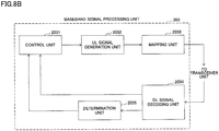
- FIG. 8B is a structural diagram of the baseband signal processing unit 203 in the mobile station 20 according to an embodiment of the present invention.
- the baseband signal processing unit 203 has a control unit 2031, an uplink (UL) signal generation unit 2032, a mapping unit 2033, a downlink (DL) signal decoding unit 2034 and a determination unit 2035.
- UL uplink
- DL downlink
- the control unit 2031 totally manages the baseband signal processing unit 203. For a signal transmitted to a base station in an uplink, data incoming from the application unit 201 is supplied to the UL signal generation unit 2032. For a signal received from the base station in a downlink, data resulting in reception operations at the DL signal decoding unit 2034 is supplied to the application unit 201. Also, the control unit 2031 performs retransmission operations such as HARQ.
- the UL signal generation unit 2032 generates a signal for transmission to a base station.
- the signal for transmission to the base station includes data and control information, and the data is mainly transmitted in a PUSCH. Also, acknowledgement information (ACK/NACK) of the data received from the base station in the PDSCH is transmitted in a PUCCH.
- ACK/NACK acknowledgement information
- the DL signal decoding unit 2034 decodes a signal received from the base station in the downlink, and the data received in the PDSCH is supplied to the control unit 2031 to be provided to the application unit 201.
- the determination unit 2035 performs retransmission determination for the signal received in the PDSCH. If the PDSCH is successfully received, the determination unit 2035 generates acknowledgement information (ACK) indicating that no retransmission is needed, and otherwise if the PUSCH is unsuccessfully received, the determination unit 2035 generates acknowledgement information (NACK) indicating that retransmission is needed.
- ACK acknowledgement information
- NACK acknowledgement information
- the base station assigns a PDCCH resource such that the PUCCH conflict cannot arise, that is, the base station sets n CCE and N PUCCH in formula (1) such that the PUCCH conflict cannot arise, and accordingly no special operation other than the above operations is needed for the function units in the mobile station 20.
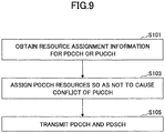
- FIG. 9 is a flowchart of a transmission method in the base station 10 according to the first approach of an embodiment of the present invention.
- the resource assignment information storage unit 1037 stores PDCCH resource assignment information or PUCCH resource assignment information.
- the PDCCH resource assignment information may be n CCE in the above formula (1) or other values indicative of the PDCCH resource assignment position.
- the PUCCH resource assignment information may be N PUCCH and/or N PUCCH in the above formula (1) or other values indicative of the PUCCH resource assignment position.
- the downlink control resource determination unit 1035 obtains the PDCCH or PUCCH resource assignment information from the resource assignment information storage unit 1037 (step S101). For example, if data is transmitted to a mobile station in a certain subframe, the downlink control resource determination unit 1035 determines whether a MTC terminal transmits a PUCCH in the PUCCH corresponding to the subframe, and if the MTC terminal transmits the PUCCH, the PUCCH resource assignment information for the MTC terminal is obtained.
- the downlink control resource determination unit 1035 assigns a PDCCH resource with reference to the obtained resource assignment information such that the PUCCH conflict cannot arise (step S103). For example, if the MTC terminal transmits the PUCCH in the PUCCH corresponding to the certain subframe, the PDCCH resource is assigned such that the PUCCH resource assignment position cannot overlap.
- the PDCCH and the PUSCH are mapped into a resource block at the mapping unit 1033 and transmitted to the mobile station (step S105).
- FIG. 10 illustrates that the PUCCH conflict is reduced in accordance with the second approach of an embodiment of the present invention.
- LTE terminals and MTC terminals use a retransmission technique to improve reception quality.
- HARQ is used as the retransmission technique.
- ACK and NACK are defined as acknowledgement information indicative of results of retransmission determination
- the LTE terminals transmit the acknowledgement information (ACK/NACK) indicative of results of PDSCH retransmission determination.
- the MTC terminals transmit only the NACK of the acknowledgement information (ACK/NACK).
- MTC terminal 0 in the enhanced coverage mode resides at a position having good reception environment.
- the MTC terminal 0 will successfully receive iteratively transmitted PDSCHs and accordingly does not transmit the PUCCH(ACK).
- the base station 10 and the mobile station 20 according to the second approach of an embodiment of the present invention are arranged similar to FIGS. 7A , 7B , 8A and 8B . Operations in function units in the base station 10 and the mobile station 20 according to the second approach of an embodiment of the present invention are described below with reference to FIG. 12 .
- FIG. 12 is a flowchart of a retransmission control method in the mobile station 20 according to the second approach of an embodiment of the present invention.
- the DL signal decoding unit 2034 decodes control information indicated in the PDCCH and obtains assignment information. Also, the DL signal decoding unit 2034 decodes data transmitted in the PDSCH based on the assignment information indicated in the PDCCH (step S201).
- the determination unit 2035 determines whether retransmission for the PDSCH is needed (step S203). If the PDSCH is unsuccessfully received, the determination unit 2035 generates acknowledgement information (NACK) indicating that the retransmission is needed.
- NACK acknowledgement information
- n PUCCH n CCE +N PUCCH (1)
- the determination unit 2035 may terminate the operation without generating the acknowledgement information (ACK).
- the base station 10 since the mobile station 20 does not transmit the ACK, the base station 10 cannot determine which the mobile station is in a no-response state (DTX) or a reception successful state (ACK) in the retransmission process. Accordingly, if no PUCCH response is received, the control unit 1031 in the base station 10 for controlling retransmission to the mobile station considers that the mobile station 20 has successfully received the PDSCH (considering as ACK).
- the MTC terminal transmits the acknowledgement information (ACK) indicating that the retransmission is not needed, or it may be assumed that the MTC terminal may transmit only the acknowledgement information (NACK) indicating that the retransmission is needed as the same operation as the PUCCH.
- ACK acknowledgement information
- NACK acknowledgement information
- FIG. 13 illustrates that the PUCCH conflict is avoided in accordance with the third approach of an embodiment of the present invention.
- a base station indicates PUCCH resources or multiple candidates of PUCCH resources to be used for a terminal to the terminal by upper layer signaling (for example, RRC (Radio Resource Control) signaling) beforehand. Since the base station assigns the PDCCH and PDSCH resources for the terminal communicating with the base station, the base station recognizes to which resources the PDCCH has been assigned (PDCCH resource assignment information), and as a result, the base station recognizes in which resource the PUCCH will be received (PUCCH resource assignment information).
- RRC Radio Resource Control
- the base station indicates a PUCCH resource to be used by the MTC terminal to the MTC terminal based on the PDCCH and PUCCH resource assignment information.
- This indication may be transmitted in RRC signaling, and specific PUCCH resources may be indicated to the respective MTC terminals.
- the specific PUCCH resources may be indicated in a certain field in DCI (Downlink Control Information). This field may be newly defined, or some existing field may be used.
- the MTC terminal Upon receiving the indication, the MTC terminal transmits the PUCCH in the indicated resource.
- the base station determines a PUCCH resource to be used by the MTC terminal from PUCCH resource candidates signaled beforehand and transmits an indicator (ARI) for determining the PUCCH resource to the MTC terminal.
- the ARI transmitted to the MTC terminal indicates which of the PUCCH resource candidates signaled beforehand is to be used.
- information indicative of which of the four patterns is to be used can be defined in two bits.
- the two bit information may be indicated to the MTC terminal by using the ARI (ACK Indicator field) in DCI (Downlink Control Information) defined in an existing specification. It is assumed that the MTC terminal knows in which DCI the ARI is indicated beforehand. For example, the ARI may be indicated to the MTC terminal by using a part of DCI for transmitting assignment information (DL assignment).
- ARI ACK Indicator field
- DCI Downlink Control Information
- the MTC terminal receives the indicator for determining the PUCCH resource and transmits the PUCCH in accordance with the received indicator.
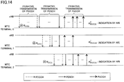
- the base station indicates to the MTC terminal 0 a specific resource for the PUCCH or the ARI indicating which of the PUCCH resource candidates signaled beforehand is to be used such that the PUCCH conflict cannot arise.
- the MTC terminal 0 transmits the PUCCH by using the indicated specific resource instead of the PUCCH resource derived from formula (1) or uses the information signaled by the ARI to determine and transmit the PUCCH resource.
- FIG. 14 illustrates that the PUCCH conflict is avoided in the case where multiple MTC terminals communicate. Also in this case, as described in conjunction with FIG. 13 , a base station indicates to the MTC terminal a PUCC resource determined based on PDCCH and PUCCH resource assignment information such that the PUCCH conflict cannot arise or indicates to the MTC terminal an ARI indicating which of PUCCH resource candidates signaled beforehand is to be used. As a result, even if the multiple MTC terminals communicate simultaneously, the PUCCH conflict can be avoided.
- the base station 10 and the mobile station 20 according to the third approach of an embodiment of the present invention are arranged similar to FIGS. 7A , 7B , 8A and 8B . Operations in respective functional units in the base station 10 and the mobile station 20 according to the third approach of an embodiment of the present invention are described below with reference to FIGS. 15 and 16 .
- FIG. 15 is a flowchart of a transmission method in the base station 10 according to the third approach of an embodiment of the present invention.
- the base station 10 indicates multiple candidates of PUCCH resources to a terminal by upper layer signaling beforehand (step S301).
- the resource assignment information storage unit 1037 stores PDCCH resource assignment information or PUCCH resource assignment information.
- the PDCCH resource assignment information may be n CCE in the above formula (1) or other values indicating the PDCCH resource assignment position.
- the PUCCH resource assignment information may be N PUCCH in the above formula (1) or other values indicating the PUCCH resource assignment position.
- the downlink control resource determination unit 1035 obtains the PDCCH or PUCCH resource assignment information from the resource assignment information storage unit 1037 (step S303). For example, if data is transmitted to the MTC terminal in multiple subframes, the downlink control resource determination unit 1035 determines whether other terminals transmit the PUCCH in the respective PUCCHs corresponding to these multiple subframes, and if the terminals transmit the PUCCH, obtains the PUCCH resource assignment information.
- the downlink control resource determination unit 1035 determines whether the PUCCH conflict involved in assigning the PDCCH to the MTC terminal can arise with reference to the obtained resource assignment information.
- the downlink control resource determination unit 1035 determines the PUCCH resource for the MTC terminal such that the PUCCH conflict cannot arise (step S307).
- the determined PUCCH resource is indicated to the MTC terminal, or an indicator to indicate the determined PUCCH resource to the MTC terminal is generated as control information at the DL signal generation unit 1032, which is transmitted to the MTC terminal in the PDCCH (step S309).
- the indicator to determine the PUCCH resource is a value indicating which of PUCCH resource candidates signaled by upper layer signaling beforehand is to be used.
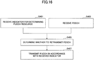
- FIG. 16 is a flowchart of a retransmission control method in the mobile station 20 according to the third approach of an embodiment of the present invention.
- the DL signal decoding unit 2034 receives and decodes an indicator for determining which of the PUCCH resource candidates is to be used, or the PUCCH resource to be used is indicated from the base station (step S401).
- the DL signal decoding unit 2034 receives data transmitted in the PDSCH from the base station (step S403) .
- Step S403 may be performed after step S401, step S403 may be performed before step S401, and step S401 and step S403 may be simultaneously performed (in the same subframe).
- the determination unit 2035 determines whether retransmission is needed for the PDSCH (step S405). If the PDSCH is unsuccessfully received, the determination unit 2035 generates acknowledgement information (NACK) indicating that the retransmission is needed. If the PDSCH is successfully received, the determination unit 2035 generates acknowledgement information (ACK) indicating that the retransmission is not needed.
- NACK acknowledgement information
- ACK acknowledgement information
- the PUCCH resource indicated by the mapping unit 2033 is assigned, or the PUCCH resource is assigned at the mapping unit 2033 in accordance with the received indicator, which is transmitted in the PUCCH.
- the ARI is used to explicitly indicate to the mobile station which of the PUCCH resource candidates indicated by upper layer signaling beforehand is to be used, but the base station may indicate an offset value to shift the PUCCH resource in any of indication manners as stated below (implicit indication).
- formula (1) indicative of the PUCCH resource may be represented as formula (2) below.
- n PUCCH n CCE +N PUCCH + ⁇ offset (2)
- ⁇ offset to shift the PUCCH resource is determined by the base station to be a value corresponding to the PUCCH resource to be used by the MTC terminal.
- the offset value ⁇ offset may be set to be i) a fixed value, ii) a value configured in RRC, iii) DCI or iv) a PCFICH (Physical Control Format Indicator Channel) in a PDSCH subframe.
- a PCFICH Physical Control Format Indicator Channel
- the ⁇ offset value may be set to a fixed value, for example, the maximum CCE.
- the ⁇ offset value may be indicated from the base station in RRC.
- the ⁇ offset value may be indicated in a field (such as an ARI) in DCI from the base station. In this case, the relationship between the indicated bit value of the field and ⁇ offset is separately signaled or incorporated in the user terminal beforehand.
- the field may be newly defined, or some existing field may be used.
- the ⁇ offset value may be configured based on the PCFICH value in the PDSCH subframe.
- the PCFICH is to indicate the number of PDCCH symbols occupied in the subframe.
- the ⁇ offset value may be configured based on the number of CFIs (Control Format Indicators) in the PDSCH subframe derived based on the PCFICH value.
- the mobile station transmits the PUCCH in a resource derived from formula (2). Note that if the offset value is used, it is unnecessary to indicate multiple PUCCH resource candidates to the terminal beforehand.
- the indicator for determining the PUCCH resource may use not the ARI in the DCI but other information items.
- a new bit may be defined in some existing or new DCIs. By defining the new bit, the number of PUCCH candidates can be flexibly defined.
- a two-bit TPC (Transmit Power Control) field may be used as the indicator for determining the PUCCH resource.
- the enhanced coverage mode of MTC terminals cannot control transmission power based on a TPC command.
- the user terminal performs transmission at the maximum transmission power, or the transmission power may be determined by combining with closed-loop control type of transmission power control by interpreting a correction value due to the TPC command as 0 dB.
- a two-bit RV (Redundancy Version) field may be used as the indicator for determining the PUCCH resource.
- the RV bit is used to determine a redundant bit pattern at retransmission.
- the same RV pattern is always used for the enhanced coverage mode of MTC terminals.
- the RV pattern is switched in a predefined order (for example, RV0 ⁇ RV1 ⁇ RV2 ⁇ RV3).
- a part of a HPN (HARQ Process Number) field indicative of a retransmission process number may be used as the indicator for determining the PUCCH resource.
- the maximum process number of retransmissions is limited by using the number of bits in the HPN field as the indicator.
- a combination of the TPC field, the RV field and the HPN field as stated above may be used as the indicator for determining the PUCCH resource.
- the PUCCH conflict among terminals can be avoided or reduced.
- the base station assigns a PDSCH resource such that conflict cannot arise at a base station, and accordingly the PUCCH conflict can be totally avoided. Also, the avoidance can be achieved by resource assignment at the base station, and no effect on the terminal is provided.
- a mobile station does not transmit ACK in the PUCCH, which does not provide any effect on the PDCCH resource assignment at the base station. Also, it is possible to prevent an increase in the probability that the PDCCH cannot be transmitted.
- the PUCCH conflict cannot be totally avoided, and the base station cannot determine whether DTX or ACK occurs.
- FIG. 17 illustrates a PUCCH conflict probability and a PDCCH transmission limitation probability (the probability that the PDCCH cannot be transmitted) according to an embodiment of the present invention.
- a simulation result in FIG. 17 is found under the same condition as that in FIG. 4 .
- the PDCCH conflict probability is higher.
- the PUCCH conflict probability cannot be 0, but the PUCCH conflict probability can be reduced compared to the conventional manners.
- the PDCCH transmission limitation probability is higher.
- the PDCCH transmission limitation probability is higher by about 10% compared to the conventional manners.
- the second and third manners it is possible to prevent an increase in the PDCCH transmission limitation probability, which is substantially similar to the conventional manners.
- the base station and the mobile station according to embodiments of the present invention are described by using functional block diagrams, but the base station and the mobile station according to embodiments of the present invention may be implemented in hardware, software or combinations thereof. Also, respective functional units may be used in combinations as needed. Also, the method according to embodiments of the present invention may be implemented in an order different from the order as illustrated in embodiments.
Landscapes
- Engineering & Computer Science (AREA)
- Signal Processing (AREA)
- Computer Networks & Wireless Communication (AREA)
- Mobile Radio Communication Systems (AREA)
Applications Claiming Priority (3)
| Application Number | Priority Date | Filing Date | Title |
|---|---|---|---|
| JP2014016189 | 2014-01-30 | ||
| JP2014059259A JP6159672B2 (ja) | 2014-01-30 | 2014-03-20 | 基地局、送信方法、移動局及び再送制御方法 |
| PCT/JP2014/082483 WO2015114952A1 (ja) | 2014-01-30 | 2014-12-09 | 基地局、送信方法、移動局及び再送制御方法 |
Publications (2)
| Publication Number | Publication Date |
|---|---|
| EP3101982A1 true EP3101982A1 (de) | 2016-12-07 |
| EP3101982A4 EP3101982A4 (de) | 2017-01-25 |
Family
ID=53756546
Family Applications (1)
| Application Number | Title | Priority Date | Filing Date |
|---|---|---|---|
| EP14880523.7A Withdrawn EP3101982A4 (de) | 2014-01-30 | 2014-12-09 | Basisstation, übertragungsverfahren, mobilstation und rückübertragungssteuerungsverfahren |
Country Status (5)
| Country | Link |
|---|---|
| US (1) | US20170055249A1 (de) |
| EP (1) | EP3101982A4 (de) |
| JP (1) | JP6159672B2 (de) |
| CN (1) | CN105934997B (de) |
| WO (1) | WO2015114952A1 (de) |
Cited By (3)
| Publication number | Priority date | Publication date | Assignee | Title |
|---|---|---|---|---|
| EP3383112A4 (de) * | 2016-01-08 | 2018-12-26 | NTT DoCoMo, Inc. | Benutzerendgerät, drahtlose basisstation und drahtloskommunikationsverfahren |
| CN109842867A (zh) * | 2017-11-24 | 2019-06-04 | 大唐移动通信设备有限公司 | 一种eMTC PUCCH资源预留方法及装置 |
| EP3468280A4 (de) * | 2016-07-01 | 2020-02-26 | LG Electronics Inc. -1- | Verfahren zum senden/empfangen eines uplink-signals zwischen einer basisstation und einem endgerät in einem drahtloskommunikationssystem und vorrichtung zur unterstützung davon |
Families Citing this family (18)
| Publication number | Priority date | Publication date | Assignee | Title |
|---|---|---|---|---|
| MY191807A (en) * | 2014-06-24 | 2022-07-16 | Sun Patent Trust | Terminal, base station, transmission method, and reception method |
| US10516517B2 (en) | 2015-01-29 | 2019-12-24 | Intel IP Corporation | System and methods for support of frequency hopping for UEs with reduced bandwidth support |
| WO2017026091A1 (ja) * | 2015-08-11 | 2017-02-16 | パナソニック インテレクチュアル プロパティ コーポレーション オブ アメリカ | 端末、基地局、送信方法及び受信方法 |
| JP6633889B2 (ja) * | 2015-10-29 | 2020-01-22 | Kddi株式会社 | 基地局装置、端末装置、通信方法及びプログラム |
| WO2017081799A1 (ja) * | 2015-11-12 | 2017-05-18 | 富士通株式会社 | 端末装置、基地局装置、無線通信システム及び無線通信方法 |
| WO2018030764A1 (en) * | 2016-08-09 | 2018-02-15 | Samsung Electronics Co., Ltd. | Apparatus and method for retransmission in wireless communication system |
| CN107708209B (zh) | 2016-08-09 | 2023-10-27 | 北京三星通信技术研究有限公司 | 用于非正交多址接入的重传数据接收、发送方法及装置 |
| WO2018094618A1 (zh) * | 2016-11-23 | 2018-05-31 | 华为技术有限公司 | 一种资源分配和传输数据包的方法及设备 |
| CN110463304B (zh) * | 2017-01-06 | 2023-07-04 | 株式会社Ntt都科摩 | 用户终端及无线通信方法 |
| CN108282253B (zh) * | 2017-01-06 | 2021-04-20 | 华为技术有限公司 | 数据传输方法及装置 |
| US10680782B2 (en) | 2017-06-16 | 2020-06-09 | Qualcomm Incorporated | Strategic mapping of uplink resources |
| US10834719B2 (en) | 2017-08-01 | 2020-11-10 | Nec Corporation | Base station, terminal apparatus, first terminal apparatus, method, program, recording medium and system |
| US20210274492A1 (en) * | 2018-08-09 | 2021-09-02 | Sharp Kabushiki Kaisha | Ack and nack differentiation on pucch for harq-ack feedback of urllc pdsch transmissions |
| JP6799787B2 (ja) * | 2019-09-04 | 2020-12-16 | サン パテント トラスト | 端末、通信方法及び集積回路 |
| WO2021142734A1 (zh) | 2020-01-16 | 2021-07-22 | Oppo广东移动通信有限公司 | 业务冲突的解决方法、装置、设备及存储介质 |
| WO2021157197A1 (ja) * | 2020-02-05 | 2021-08-12 | パナソニック インテレクチュアル プロパティ コーポレーション オブ アメリカ | 端末及び通信方法 |
| JP7016047B2 (ja) * | 2020-11-02 | 2022-02-04 | サン パテント トラスト | 基地局、通信方法及び集積回路 |
| US11743864B2 (en) * | 2021-03-25 | 2023-08-29 | Qualcomm Incorporated | Techniques for unlinking physical downlink control channel (PDCCH) candidates due to PDCCH candidate dropping in deployments featuring PDCCH repetition |
Family Cites Families (9)
| Publication number | Priority date | Publication date | Assignee | Title |
|---|---|---|---|---|
| JP4511611B2 (ja) * | 2008-05-29 | 2010-07-28 | 株式会社エヌ・ティ・ティ・ドコモ | 無線リソース選択方法、無線基地局及び移動局 |
| US20140169319A1 (en) * | 2011-07-26 | 2014-06-19 | Lg Electronics Inc. | Method for transmitting uplink signal, user equipment, method for receiving uplink signal, and base station |
| CN103621168B (zh) * | 2012-06-28 | 2017-05-10 | 华为技术有限公司 | 下行数据的反馈信息的传输方法及终端、基站 |
| KR101612667B1 (ko) * | 2012-07-03 | 2016-04-14 | 엘지전자 주식회사 | 무선통신 시스템에서 상향링크 제어 채널을 위한 자원 할당 방법 및 장치 |
| JP2014016189A (ja) | 2012-07-06 | 2014-01-30 | Panasonic Corp | 半導体センサ |
| CN105210321B (zh) * | 2013-05-12 | 2019-06-07 | Lg电子株式会社 | 用于接收下行控制信息dci的方法和装置 |
| US9924536B2 (en) * | 2013-05-22 | 2018-03-20 | Lg Electronics Inc. | Communication method for terminal in wireless communication system and terminal using same |
| KR101904572B1 (ko) * | 2013-09-27 | 2018-10-08 | 주식회사 케이티 | 단말을 위한 상향 링크 제어 채널 자원 설정 방법 및 장치 |
| CN104767595A (zh) * | 2014-01-07 | 2015-07-08 | 中兴通讯股份有限公司 | Harq-ack反馈信息的传输方法、系统及终端和基站 |
-
2014
- 2014-03-20 JP JP2014059259A patent/JP6159672B2/ja active Active
- 2014-12-09 EP EP14880523.7A patent/EP3101982A4/de not_active Withdrawn
- 2014-12-09 WO PCT/JP2014/082483 patent/WO2015114952A1/ja not_active Ceased
- 2014-12-09 CN CN201480074014.6A patent/CN105934997B/zh active Active
- 2014-12-09 US US15/113,966 patent/US20170055249A1/en not_active Abandoned
Cited By (5)
| Publication number | Priority date | Publication date | Assignee | Title |
|---|---|---|---|---|
| EP3383112A4 (de) * | 2016-01-08 | 2018-12-26 | NTT DoCoMo, Inc. | Benutzerendgerät, drahtlose basisstation und drahtloskommunikationsverfahren |
| EP3468280A4 (de) * | 2016-07-01 | 2020-02-26 | LG Electronics Inc. -1- | Verfahren zum senden/empfangen eines uplink-signals zwischen einer basisstation und einem endgerät in einem drahtloskommunikationssystem und vorrichtung zur unterstützung davon |
| US10694507B2 (en) | 2016-07-01 | 2020-06-23 | Lg Electronics Inc. | Method for transmitting/receiving uplink signal between base station and terminal in wireless communication system, and device for supporting same |
| US11317385B2 (en) | 2016-07-01 | 2022-04-26 | Lg Electronics Inc. | Method for transmitting/receiving uplink signal between base station and terminal in wireless communication system, and device for supporting same |
| CN109842867A (zh) * | 2017-11-24 | 2019-06-04 | 大唐移动通信设备有限公司 | 一种eMTC PUCCH资源预留方法及装置 |
Also Published As
| Publication number | Publication date |
|---|---|
| JP2015164279A (ja) | 2015-09-10 |
| US20170055249A1 (en) | 2017-02-23 |
| JP6159672B2 (ja) | 2017-07-05 |
| WO2015114952A1 (ja) | 2015-08-06 |
| CN105934997B (zh) | 2019-08-02 |
| EP3101982A4 (de) | 2017-01-25 |
| CN105934997A (zh) | 2016-09-07 |
Similar Documents
| Publication | Publication Date | Title |
|---|---|---|
| US20170055249A1 (en) | Base station, transmission method, mobile station and retransmission control method | |
| US10708889B2 (en) | Method and apparatus for indicating subframes associated with a hybrid automatic repeat request feedback | |
| CN115918193B (zh) | 通信方法、终端设备和计算机可读介质 | |
| CN110932820B (zh) | 发送和接收上行控制信息的方法以及通信装置 | |
| EP2995106B1 (de) | Verfahren, vorrichtung und computerprogramm zur drahtlosen kommunikation | |
| EP2745593B1 (de) | Kommunikationsplanung | |
| JP7290180B2 (ja) | 端末装置及びネットワーク装置によって実行される方法、端末装置、並びにネットワーク装置 | |
| US10051633B2 (en) | Method and apparatus for carrier aggregation | |
| JP6720371B2 (ja) | キャリアアグリゲーションベースの無線通信システムにおける通信方法(communication method in wireless communication system on basis of carrier aggregation) | |
| US20180077721A1 (en) | Method and apparatus for scheduling uplink transmissions with reduced latency | |
| TWI801182B (zh) | 用於重傳之混成自動重複請求確認(harq-ack)碼簿之指示技術 | |
| JP2014525690A (ja) | Fddscellの肯定/否定応答伝送のためのpdsch割当て標示情報 | |
| JP7327483B2 (ja) | マルチtrp送信のための方法、デバイス、及びプログラム | |
| US20240349266A1 (en) | Methods, devices, and computer readable medium for communication | |
| WO2025208885A1 (zh) | 参数配置方法、设备及存储介质 | |
| US11843560B2 (en) | Determination of feedback timing | |
| AU2016417122B2 (en) | Determination of feedback timing |
Legal Events
| Date | Code | Title | Description |
|---|---|---|---|
| PUAI | Public reference made under article 153(3) epc to a published international application that has entered the european phase |
Free format text: ORIGINAL CODE: 0009012 |
|
| 17P | Request for examination filed |
Effective date: 20160805 |
|
| AK | Designated contracting states |
Kind code of ref document: A1 Designated state(s): AL AT BE BG CH CY CZ DE DK EE ES FI FR GB GR HR HU IE IS IT LI LT LU LV MC MK MT NL NO PL PT RO RS SE SI SK SM TR |
|
| AX | Request for extension of the european patent |
Extension state: BA ME |
|
| A4 | Supplementary search report drawn up and despatched |
Effective date: 20170102 |
|
| RIC1 | Information provided on ipc code assigned before grant |
Ipc: H04W 72/04 20090101AFI20161221BHEP Ipc: H04L 5/00 20060101ALI20161221BHEP |
|
| DAX | Request for extension of the european patent (deleted) | ||
| 17Q | First examination report despatched |
Effective date: 20191106 |
|
| STAA | Information on the status of an ep patent application or granted ep patent |
Free format text: STATUS: THE APPLICATION HAS BEEN WITHDRAWN |
|
| 18W | Application withdrawn |
Effective date: 20200204 |