EP3102343B1 - Vorrichtung und verfahren zum absaugen und/oder ausblasen eines bauteils - Google Patents
Vorrichtung und verfahren zum absaugen und/oder ausblasen eines bauteils Download PDFInfo
- Publication number
- EP3102343B1 EP3102343B1 EP15714394.2A EP15714394A EP3102343B1 EP 3102343 B1 EP3102343 B1 EP 3102343B1 EP 15714394 A EP15714394 A EP 15714394A EP 3102343 B1 EP3102343 B1 EP 3102343B1
- Authority
- EP
- European Patent Office
- Prior art keywords
- suction
- component
- vapours
- axis
- sucked
- Prior art date
- Legal status (The legal status is an assumption and is not a legal conclusion. Google has not performed a legal analysis and makes no representation as to the accuracy of the status listed.)
- Active
Links
Images

Classifications
-
- B—PERFORMING OPERATIONS; TRANSPORTING
- B08—CLEANING
- B08B—CLEANING IN GENERAL; PREVENTION OF FOULING IN GENERAL
- B08B15/00—Preventing escape of dirt or fumes from the area where they are produced; Collecting or removing dirt or fumes from that area
- B08B15/007—Fume suction nozzles arranged on a closed or semi-closed surface, e.g. on a circular, ring-shaped or rectangular surface adjacent the area where fumes are produced
-
- B—PERFORMING OPERATIONS; TRANSPORTING
- B08—CLEANING
- B08B—CLEANING IN GENERAL; PREVENTION OF FOULING IN GENERAL
- B08B15/00—Preventing escape of dirt or fumes from the area where they are produced; Collecting or removing dirt or fumes from that area
- B08B15/04—Preventing escape of dirt or fumes from the area where they are produced; Collecting or removing dirt or fumes from that area from a small area, e.g. a tool
-
- B—PERFORMING OPERATIONS; TRANSPORTING
- B08—CLEANING
- B08B—CLEANING IN GENERAL; PREVENTION OF FOULING IN GENERAL
- B08B5/00—Cleaning by methods involving the use of air flow or gas flow
- B08B5/02—Cleaning by the force of jets, e.g. blowing-out cavities
-
- B—PERFORMING OPERATIONS; TRANSPORTING
- B23—MACHINE TOOLS; METAL-WORKING NOT OTHERWISE PROVIDED FOR
- B23K—SOLDERING OR UNSOLDERING; WELDING; CLADDING OR PLATING BY SOLDERING OR WELDING; CUTTING BY APPLYING HEAT LOCALLY, e.g. FLAME CUTTING; WORKING BY LASER BEAM
- B23K26/00—Working by laser beam, e.g. welding, cutting or boring
- B23K26/16—Removal of by-products, e.g. particles or vapours produced during treatment of a workpiece
Definitions
- the invention relates to a device for sucking off and/or blowing out a component, in particular a thin-walled component, in particular a pillar covering according to the wording of claim 1 and a method for sucking off and/or blowing out components, in particular thin-walled components, in particular pillar coverings according to the wording of claim 7.
- EP 2 444 189 A1 discloses a cutting table for a flame cutting system, wherein a fixed suction channel that can be connected to an exhaust air fan is provided in a console and a method for this according to the preamble of claims 1 and 7.
- DE 195 49 176 A1 discloses a method for blowing out and cleaning recesses in workpieces, wherein gas is compressed into a container and then expanded into at least one recess of the workpiece to remove in particular chips that are deposited in the recesses.
- the object of the present invention is to provide a flexible device that makes it possible to safely and reliably remove the disadvantageous vapors and soot without having to accept the disadvantages of the prior art.
- a device for sucking off and/or blowing out a component in particular a thin-walled component, in particular a pillar covering, which is to be processed with a laser scanner, with vapors being produced, comprising: at least one switchable suction flap which is closed in a predetermined manner with a controller can be opened and closed, so that when vapors occur in a predetermined area, the extraction flap assigned to the area is to be actuated and the vapors are sucked out and/or blown out, with further component areas being able to be sucked off by being able to rotate about an axis of rotation in the longitudinal direction of the suction device.
- suction flap also means an alternative blow-out flap and the term suction can also be used to blow out.
- the invention prevents burns and sooting of the components, since the vapors produced are extracted on site in a targeted and rapid manner.
- suction flaps are provided, which are activated when vapors occur in predetermined areas in such a way that the respective area that is to be processed is to be suctioned off essentially locally.
- a suction channel for sucking off the vapors in particular a plurality of suction channels
- a channel device in particular assigned to the suction flaps, which lead into predetermined areas of the component to be sucked off and suck them off.
- the components can be built up via the channel device in the sense of a device centering on the axis of rotation.
- the channel device includes, for example, a milled aluminum contour or a cast material.
- the channel device can easily be adapted to the spatial conditions of the component to be extracted, whereby it does not have to have any extraction flaps itself, as a result of which the effort, space requirement and costs can be kept lower.
- a rotary axis that can be rotated by approximately +/-120° is built into a laser station of the laser scanner.
- the suction is integrated in particular in the axis of rotation and takes place in particular via a suction channel.
- switchable suction flaps are integrated in the suction channel or several suction channels, which can be opened and closed individually, depending on local requirements. The suction flaps are controlled in such a way that contamination is avoided.
- an axis of rotation is integrated in a substantially vertical direction, which makes the component rotatable about a vertical axis, as a result of which additional areas of the component can be vacuumed off.
- an axis plate with one or more bores is assigned to the vertical axis of rotation, which, depending on the rotational position, at least partially covers the suction flap and/or suction flaps and/or at least partially leaves them uncovered, so that further component areas can be suctioned off.
- the suction flap comprises a movable cylinder, in particular a pneumatic cylinder and/or an electric cylinder.
- the object is also achieved by a method for sucking off and/or blowing out components, in particular thin-walled components, in particular pillar coverings, which are to be processed with a laser scanner, with vapors being produced, in particular using a device according to one of Claims 1 to 6, characterized characterized in that the vapors via at least one suction channel, in particular several suction ducts, for sucking off the fumes, are sucked off with at least one switchable suction flap, which can be opened and closed in a predetermined manner with a controller, so that when fumes occur in the predetermined area, the suction flap assigned to the area is actuated and the fumes in are sucked off from the predetermined area, further component areas being sucked off by rotation about an axis of rotation in the longitudinal direction of the suction device.
- suction flaps are provided, with the suction flaps being able to be opened and closed in a manner coordinated with a processing location, so that the vapors are sucked off locally.
- the component to be processed is rotated about a longitudinal axis and/or transverse axis of rotation between processing steps and/or during processing steps, suction being carried out with the suction flaps beforehand and/or during and/or afterwards.
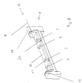
- the device 1 shows a device 1 for sucking off and/or blowing out a component, for example from FIG 3 , in perspective view.
- the device 1 has an axis of rotation 7 in the longitudinal direction 8 .
- the axis of rotation 7 can be rotated in particular by +/-120° and is integrated into a laser station (not shown) for a laser scanner, for example.
- the device 1 is equipped, for example, with a rotary drive 18 and a counter bearing 19 .
- suction flaps 3 are provided, for example four.
- a pressure supply in particular a vacuum supply opened and closed for extraction by a controller according to a predetermined sequence in such a way that vapors produced by a processing step in a component arranged above it in predetermined areas, in particular during laser scanner cutting, are extracted in a targeted and direct manner.
- the pressure supply is more detailed in 4 shown.
- the components can be built up on the axis of rotation 7 via a device centering 20 .
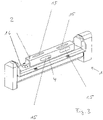
- FIG. 2 shows a device 1 for sucking off and/or blowing out a component in a section with suction flaps 3.
- One of the suction flaps 17 is open and the other suction flap 21 is closed.
- An exemplary structure of a suction flap 3 is shown in 4 shown in section.
- FIG. 3 shows a device 1 for sucking off and/or blowing out a component 2.
- the component 2 is arranged on the upper side 16 of the device 1 above suction flaps 3.
- FIG. Machining sections 15 are incorporated into the component 2, for example by a laser scanner.
- the suction flaps, which are arranged underneath, are controlled according to the invention in such a way that the closest area 4 of the component 2 in which vapors are produced can be sucked off quickly and safely.
- the component 2 is trimmed, for example in a zero position, by the axis of rotation 7 in an upper region at the rear and front.
- the nearest suction flap is open for this purpose.
- the suction flap 3 now opens and the cutouts are trimmed.
- the axis of rotation 7 then rotates through 90° and the sides are trimmed. These can still be trimmed with the suction channel 6.
- the cutouts on the side flanks are then trimmed.
- the suction flap 3 closes and the suction flap 3 opens. Then these sections can be cropped.
- Component 2 then rotates 180° and the second side can be trimmed.
- the suction flap 3 can also be used for this.
- the suction flap 3 then opens and the cutouts can be processed on the side. This control sequence ensures smoke-free production of the components 2.
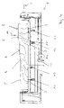
- FIG. 4 shows a sectional view of a device 1 for sucking off and/or blowing out a component 2.
- a channel device 5 is arranged on the upper side 16 of the device 1.
- FIG. The channel device 5 has suction channels 6, which can be milled into aluminum, for example, or can be produced with a die-casting mold.
- the channel device 5 can be easily adapted to the spatial conditions of the component 2, and it does not have to have any more complex suction flaps.
- the same suction flaps 3 can then be used for a wide variety of components 2, since they are arranged centrally—as shown by way of example.
- the control via the suction flaps in the rotary axes has the advantage that active flaps are no longer required in the duct devices and the effort, space requirement and costs can be kept lower as a result.
- the suction channels 6 are assigned to the suction flaps 3 and are designed to be adapted to the local conditions of the component 2 so that targeted, individual suction can take place on site.
- a flow direction 14 is shown by way of example an opened suction plate 17 into the device 1 and then to an outlet 22.
- the suction flaps 3 are provided with a cylinder 13 for actuation, in particular a pneumatic cylinder and/or an electric cylinder, as a result of which the suction flaps can be actuated quickly and reliably. In addition or as an alternative to suction, blowing out through the flaps 3 can also take place.
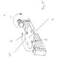
- figure 5 shows a device for sucking off and/or blowing out a component 2 with several axes of rotation.
- a second axis of rotation 9 is used perpendicular to the first axis of rotation 7, which can additionally rotate the component 2 about a second axis.
- the axle plate 11 is provided with four holes through which the suction can be carried out. In each case in the fixed position, suction can then be carried out upwards through the open suction flap control in the lower area, which was also present previously. This means that no additional suction flap control is necessary, but the existing one can be used.
- the advantage is that the component can be rotated again around a second axis, further increasing flexibility.
Landscapes
- Laser Beam Processing (AREA)
Description
- Die Erfindung betrifft eine Vorrichtung zum Absaugen und/oder Ausblasen eines Bauteils, insbesondere eines dünnwandigen Bauteils, insbesondere einer Säulenverkleidung nach dem Wortlaut von Anspruch 1 und ein Verfahren zum Absaugen und/oder Ausblasen von Bauteilen, insbesondere dünnwandigen Bauteilen, insbesondere Säulenverkleidungen nach dem Wortlaut von Anspruch 7.
-
EP 2 444 189 A1 offenbart einen Schneidtisch für eine Brennschneidanlage, wobei in einer Konsole ein an ein Abluftgebläse anschließbarer, feststehender Absaugkanal vorgesehen ist und ein Verfahren dafür, gemäß dem Oberbegriff der Ansprüche 1 und 7. -
DE 195 49 176 A1 offenbart ein Verfahren zum Ausblasen und Reinigen von Ausnehmungen von Werkstücken, wobei Gas in einen Behälter komprimiert und anschließend in zumindest eine Ausnehmung des Werkstücks expandiert wird zur Entfernung von insbesondere Spänen, die in den Ausnehmungen abgelagert sind. - Beim Bearbeiten von Kunststoffbauteilen, insbesondere von Säulenverkleidungen für Automobil-Innenverkleidungen, werden am Rand überstehende Textilien oder auch innenliegende Ausschnitte insbesondere mit einem Laserscanningverfahren beschnitten. Die Ausschnitte sind rundherum um das Bauteil verteilt und können auch sehr nahe zueinander oder sehr nahe am Rand liegen. Bei diesen Ausschnitten besteht die Gefahr darin, dass Schmauch und Ruß, die aus dem Laserverfahren entstehen, durch Luftströmungen über das Bauteil gezogen werden und es zu irreversiblen Beschädigungen des Bauteils kommt.
- Aufgabe der vorliegenden Erfindung ist es, eine flexible Vorrichtung bereitzustellen, die es ermöglicht, die nachteiligen Dämpfe und Ruße sicher und zuverlässig zu entfernen, ohne die Nachteile des Stands der Technik in Kauf zu nehmen.
- Die Aufgabe wird gelöst durch eine Vorrichtung zum Absaugen und/oder Ausblasen eines Bauteils, insbesondere eines dünnwandigen Bauteils, insbesondere einer Säulenverkleidung, die mit einem Laserscanner zu bearbeiten ist, wobei Dämpfe entstehen, umfassend: zumindest eine schaltbare Absaugklappe, die vorbestimmt mit einer Steuerung zu öffnen und zu schließen ist, so dass beim Auftreten von Dämpfen in einem vorbestimmten Bereich die dem Bereich zugeordnete Absaugklappe zu betätigen ist und die Dämpfe absaugt und/oder ausbläst, wobei durch eine Drehbarkeit um eine Drehachse in Längsrichtung der Absaugvorrichtung weitere Bauteilbereiche abzusaugen sind. Ergänzend oder alternativ zum Absaugen kann auch ein Ausblasen durch die Klappen stattfinden. In der Anmeldung ist also dementsprechend jeweils unter dem Begriff Absaugklappe auch alternativ Ausblasklappe gemeint und beim Begriff Absaugen kann auch Ausblasen vorgenommen werden.
- Durch den Laserscanner können somit insbesondere dünnwandigen Bauteile berührungslos geschnitten werden. Und durch die Erfindung wird zugleich verhindert, dass es zu Verbrennungen und Verrußungen der Bauteile kommt, da eine gezielte und schnelle Absaugung der entstandenen Dämpfe vor Ort vorgenommen wird.
- Vorteilhaft ist es, wenn vier Absaugklappen vorgesehen sind, die beim Auftreten von Dämpfen in vorbestimmten Bereichen derart angesteuert sind, dass der jeweilige Bereich, der zu bearbeiten ist, im Wesentlichen lokal abzusaugen ist.
- Vorteilhaft ist es, wenn in Fortsetzung einer Absaugklappe, insbesondere mehrerer Absaugklappen in einer Kanalvorrichtung ein Absaugkanal zum Absaugen der Dämpfe, insbesondere mehrere Absaugkanäle, insbesondere jeweils den Absaugklappen zugeordnet vorgesehen sind, die in vorbestimmte Bereiche des abzusaugenden Bauteils führen und diese absaugen. Die Bauteile können über die Kanalvorrichtung im Sinne einer Vorrichtungszentrierung auf der Drehachse aufgebaut werden. Die Kanalvorrichtung umfasst beispielhaft eine gefräste Aluminiumkontur oder ein Gussmaterial. Die Kanalvorrichtung kann auf einfache Weise an die räumlichen Gegebenheiten des abzusaugenden Bauteils angepasst werden, wobei sie selbst keine Absaugklappen aufweisen muss, wodurch der Aufwand, Platzbedarf und die Kosten geringer gehalten werden können.
- Durch eine Drehbarkeit um eine Drehachse in Längsrichtung der Absaugvorrichtugn sind weitere Bauteilbereiche absaugbar. Insbesondere ist eine um etwa +/-120° drehbare Drehachse in eine Laserstation des Laserscanners eingebaut. Die Absaugung ist insbesondere in der Drehachse integriert und erfolgt insbesondere über einen Absaugkanal. Im Absaugkanal oder mehreren Absaugkanälen sind mehrere, insbesondere vier schaltbare Absaugklappen integriert, die einzeln - je nach lokalem Bedarf - geöffnet und geschlossen werden können. Die Absaugklappen werden so gesteuert, dass Verschmutzungen vermieden werden.
- Vorteilhaft ist es, wenn eine Drehachse in im Wesentlichen senkrechter Richtung integriert ist, die das Bauteil um eine senkrechte Achse drehbar macht, wodurch weitere Bauteilbereiche abzusaugen sind.
- Vorteilhaft ist es, wenn eine Achsenplatte mit einer oder mehreren Bohrungen der senkrechten Drehachse zugeordnet ist, die je nach Drehstellung die Absaugklappe und/oder Absaugklappen zumindest teilweise abdeckt und/oder zumindest teilweise frei lässt, so dass weitere Bauteilbereiche abzusaugen sind.
- Vorteilhaft ist es, wenn die Absaugklappe einen beweglichen Zylinder, insbesondere einen Pneumatikzylinder und/oder Elektrozylinder umfasst.
- Die Aufgabe wird ebenfalls gelöst durch ein Verfahren zum Absaugen und/oder Ausblasen von Bauteilen, insbesondere dünnwandigen Bauteilen, insbesondere Säulenverkleidungen, die mit einem Laserscanner zu bearbeiten sind, wobei Dämpfe entstehen, insbesondere unter Verwendung einer Vorrichtung nach einem der Ansprüche 1 bis 6, dadurch gekennzeichnet, dass die Dämpfe über zumindest einen Absaugkanal, insbesondere mehrere Absaugkanäle, zum Absaugen der Dämpfe, abgesaugt werden mit zumindest einer schaltbaren Absaugklappe, die vorbestimmt mit einer Steuerung zu öffnen und zu schließen ist, so dass beim Auftreten von Dämpfen in dem vorbestimmten Bereich die dem Bereich zugeordnete Absaugklappe betätigt wird und die Dämpfe in dem vorbestimmten Bereich absaugt werden, wobei durch eine Drehung um eine Drehachse in Längsrichtung der Absaugvorrichtung weitere Bauteilbereiche abgesaugt werden.
- Vorteilhaft ist es, wenn vier Absaugkanäle und zugeordnete Absaugklappen vorgesehen sind, wobei die Absaugklappen auf einen Bearbeitungsort abgestimmt zu öffnen und zu schließen sind, so dass die Dämpfe lokal abgesaugt werden.
- Vorteilhaft ist es, wenn das zu bearbeitende Bauteil zwischen Bearbeitungsschritten und/oder während Bearbeitungsschritten um eine Längsachse und/oder Querdrehachse gedreht wird, wobei vorher und/oder währenddessen und/oder nachher eine Absaugung mit den Absaugklappen vorgenommen wird.
- Weitere Merkmale und Vorteile der Erfindung ergeben sich aus den Ansprüchen und der nachstehenden Beschreibung, in der Ausführungsbeispiele des Gegenstands der Erfindung in Verbindung mit den Zeichnungen näher erläutert sind.
- Es zeigen:
- Fig. 1
- eine Vorrichtung zum Absaugen und/oder Ausblasen eines Bauteils in perspektivischer Ansicht,
- Fig. 2
- eine Vorrichtung zum Absaugen und/oder Ausblasen eines Bauteils in einem Ausschnitt,
- Fig. 3
- eine Vorrichtung zum Absaugen und/oder Ausblasen eines Bauteils mit einem Bauteil,
- Fig. 4
- eine Schnittdarstellung einer Vorrichtung zum Absaugen und/oder Ausblasen eines Bauteils und
- Fig. 5
- eine Vorrichtung zum Absaugen und/oder Ausblasen eines Bauteils mit mehreren Drehachsen.
-
Fig. 1 zeigt eine Vorrichtung 1 zum Absaugen und/oder Ausblasen eines Bauteils, beispielsweise ausFig. 3 , in perspektivischer Ansicht. Die Vorrichtung 1 weist eine Drehachse 7 in Längsrichtung 8 auf. Die Drehachse 7 ist insbesondere um +/- 120° drehbar und beispielhaft in eine nicht dargestellte Laserstation für einen Laserscanner integriert. Die Vorrichtung 1 ist beispielhaft mit einem Drehantrieb 18 und einem Gegenlager 19 ausgestattet. - In einer Oberseite 16 der Vorrichtung 1 sind mehrere Absaugklappen 3 vorgesehen, beispielhaft vier. Die Absaugklappen 3, die im Inneren der Vorrichtung 1 durch eine Druckversorgung insbesondere eine Unterdruckversorgung beaufschlagt sind, werden durch eine Steuerung nach einer vorbestimmten Reihenfolge derart zum Absaugen geöffnet und geschlossen, dass in einem darüber angeordneten Bauteil in vorbestimmten Bereichen durch einen Bearbeitungsschritt entstehende Dämpfe, insbesondere beim Laserscannerschneiden, gezielt und ohne Umwege abgesaugt werden. Gerade beim Laserscannerschneiden werden sehr hohe Bearbeitungsfrequenzen erreicht, die durch die vorliegende Erfindung vorteilhaft ebenso schnell durch die Absaugung begleitet werden können, wobei im Vergleich zum Erfolg eine sehr geringe Anzahl Saugbereiche eingesetzt werden. Die Druckversorgung ist detaillierter in
Fig. 4 dargestellt. Eine beispielhaft geöffnete Absaugklappe 17 ermöglicht dann eine gezielte und schnelle Absaugung eines bearbeiteten Bereiches des Bauteils. Die Bauteile können über eine Vorrichtungszentrierung 20 auf der Drehachse 7 aufgebaut werden. - Durch einen Laserscanner können insbesondere dünnwandigen Bauteile berührungslos geschnitten werden, insbesondere werden Bearbeitungsausschnitte eingebracht. Dazu ist eine erfindungsgemäße Absaugung an den Bauteilen sehr vorteilhaft, da es hier ansonsten zu Verbrennungen und einem Verrußen der Bauteile kommt.
-
Fig. 2 zeigt eine Vorrichtung 1 zum Absaugen und/oder Ausblasen eines Bauteils in einem Ausschnitt mit Absaugklappen 3. Eine der Absaugklappen 17 ist geöffnet und die andere Absaugklappe 21 ist geschlossen. Ein beispielhafter Aufbau einer Absaugklappe 3 ist inFig. 4 im Schnitt dargestellt. -
Fig. 3 zeigt eine Vorrichtung 1 zum Absaugen und/oder Ausblasen eines Bauteils 2. Das Bauteil 2 ist auf der Oberseite 16 der Vorrichtung 1 oberhalb von Absaugklappen 3 angeordnet. In dem Bauteil 2 sind Bearbeitungsausschnitte 15 eingearbeitet, beispielsweise durch einen Laserscanner. Die Absaugklappen, die darunter angeordnet sind, werden erfindungsgemäß so angesteuert, dass jeweils der am nächsten liegende Bereich 4 des Bauteils 2, in dem Dämpfe entstehen, schnell und sicher abgesaugt werden kann. - Das Bauteil 2 wird beispielsweise in einer Nullposition von der Drehachse 7 in einem oberen Bereich hinten und vorne beschnitten. Dazu ist die nächstliegende Absaugklappe geöffnet.
- Dann wird beispielsweise ein Ausschnitt nahe am Randbereich geschnitten. Hier könnte es zum Überspringen des Schmauches führen, wenn weiterhin die erste Absaugklappe geöffnet wäre. Daher öffnet nun die Absaugklappe 3 und es werden die Ausschnitte beschnitten. Nachfolgend dreht die Drehachse 7 um 90° und es werden die Seiten beschnitten. Diese können weiterhin mit dem Absaugkanal 6 beschnitten werden. Anschließend werden die Ausschnitte an den Seitenflanken beschnitten. Hierzu schließt die Absaugklappe 3 und die Absaugklappe 3 öffnet. Dann können diese Ausschnitte beschnitten werden. Nachfolgend dreht das Bauteil 2 um 180° und die zweite Seite kann beschnitten werden. Hierzu kann die Absaugklappe 3 ebenso verwendet werden. Im Anschluss daran öffnet die Absaugklappe 3 und die Ausschnitte können auf der Seite bearbeitet werden. Durch diese Steuerung Reihenfolge ist eine schmauchfreie Produktion der Bauteile 2 gewährleistet.
-
Fig. 4 zeigt eine Schnittdarstellung einer Vorrichtung 1 zum Absaugen und/oder Ausblasen eines Bauteils 2. Auf der Oberseite 16 der Vorrichtung 1 ist eine Kanalvorrichtung 5 angeordnet. Die Kanalvorrichtung 5 weist Absaugkanäle 6 auf, die beispielsweise in Aluminium eingefräst sein können oder mit einer Druckgussform hergestellt sein können. Die Kanalvorrichtung 5 kann auf einfache Weise an die räumlichen Gegebenheiten des Bauteils 2 angepasst werden, wobei sie keine aufwendigeren Absaugklappen aufweisen muss. Dieselben Absaugklappen 3 können dann für unterschiedlichste Bauteile 2 verwendet werden, da sie - wie beispielhaft dargestellt - zentral angeordnet sind. Die Ansteuerung über die Absaugklappen in den Drehachsen hat den Vorteil, dass in den Kanalvorrichtungen keine aktiven Klappen mehr benötigt werden und hierdurch der Aufwand, Platzbedarf und die Kosten geringer gehalten werden können. Die Absaugkanäle 6 sind den Absaugklappen 3 entsprechend zugeordnet geführt und jeweils an örtliche Gegebenheiten des Bauteils 2 entsprechend angepasst ausgebildet, so dass eine gezielte, individuelle Absaugung vor Ort stattfinden kann. Beispielhaft ist eine Strömungsrichtung 14 dargestellt, die durch eine geöffnete Absaugplatte 17 hindurch in die Vorrichtung 1 geleitet wird und dann zu einem Ausgang 22. - Die Absaugklappen 3 sind mit einem Zylinder 13 zur Betätigung versehen, insbesondere einem Pneumatikzylinder und/oder einem Elektrozylinder, wodurch eine schnelle und sichere Betätigung der Absaugklappen möglich wird. Ergänzend oder alternativ zum Absaugen kann auch ein Ausblasen durch die Klappen 3 stattfinden.
-
Fig. 5 zeigt eine Vorrichtung zum Absaugen und/oder Ausblasen eines Bauteils 2 mit mehreren Drehachsen. Beispielhaft wird zusätzlich zur ersten Drehachse 7 eine zweite Drehachse 9 senkrecht zur ersten Drehachse 7 eingesetzt, die das Bauteil 2 zusätzlich um eine zweite Achse drehen kann. Die Achsenplatte 11 ist mit vier Bohrungen versehen, worüber die Absaugung durchgeführt werden kann. Jeweils in der festen Stellung kann dann durch die geöffnete Absaugklappensteuerung in dem unteren Bereich, die auch vorher schon vorhanden war, die Absaugung nach oben durchgeführt werden. Somit ist keine zusätzliche Absaugklappensteuerung notwendig, sondern die vorhandene kann verwendet werden. Der Vorteil besteht darin, dass das Bauteil nochmals um eine zweite Achse gedreht werden kann und somit die Flexibilität weiter gesteigert werden. -
- 1
- Vorrichtung
- 2
- Bauteil
- 3
- Klappe, insbesondere Absaugklappe
- 4
- Bereich
- 5
- Kanalvorrichtung
- 6
- Kanal, insbesondere Absaugkanal
- 7
- Drehachse
- 8
- Längsrichtung
- 9
- Drehachse
- 10
- senkrechte Richtung
- 11
- Achsenplatte
- 12
- Bohrung
- 13
- Zylinder
- 14
- Strömungsrichtung
- 15
- Bearbeitungsausschnitt
- 16
- Oberseite
- 17
- geöffnete Absaugklappe
- 18
- Drehantrieb
- 19
- Gegenlager
- 20
- Vorrichtungszentrierung
- 21
- geschlossene Absaugklappe
- 22
- Ausgang
Claims (9)
- Vorrichtung (1) zum Absaugen und/oder Ausblasen eines Bauteils (2), insbesondere eines dünnwandigen Bauteils, insbesondere einer Säulenverkleidung, die mit einem Laserscanner zu bearbeiten ist, wobei Dämpfe entstehen, umfassend: zumindest eine schaltbare Absaugklappe (3), die vorbestimmt mit einer Steuerung zu öffnen und zu schließen ist, so dass beim Auftreten von Dämpfen in einem vorbestimmten Bereich (4) die dem Bereich zugeordnete Absaugklappe (3) zu betätigen ist und die Dämpfe absaugt und/oder ausbläst, dadurch gekennzeichnet, dass durch eine Drehbarkeit um eine Drehachse (7) in Längsrichtung (8) der Absaugvorrichtung (1) weitere Bauteilbereiche abzusaugen sind.
- Vorrichtung nach Anspruch 1, dadurch gekennzeichnet, dass vier Absaugklappen (3) vorgesehen sind, die beim Auftreten von Dämpfen in vorbestimmten Bereichen derart angesteuert sind, dass der jeweilige Bereich (4), der zu bearbeiten ist, im Wesentlichen lokal abzusaugen ist.
- Vorrichtung nach Anspruch 1 oder 2, dadurch gekennzeichnet, dass in Fortsetzung einer Absaugklappe (3), insbesondere mehrerer Absaugklappen (3) in einer Kanalvorrichtung (5) ein Absaugkanal (6) zum Absaugen der Dämpfe, insbesondere mehrere Absaugkanäle (6), insbesondere jeweils den Absaugklappen zugeordnet vorgesehen sind, die in vorbestimmte Bereiche (4) des abzusaugenden Bauteils (2) führen und diese absaugen.
- Vorrichtung nach einem der Ansprüche 1 bis 3, dadurch gekennzeichnet, dass eine Drehachse (9) in im Wesentlichen senkrechter Richtung (10) integriert ist, die das Bauteil (2) um eine senkrechte Achse drehbar macht, wodurch weitere Bauteilbereiche abzusaugen sind.
- Vorrichtung nach einem der Ansprüche 1 bis 4, dadurch gekennzeichnet, dass eine Achsenplatte (11) mit einer oder mehreren Bohrungen (12) der senkrechten Drehachse (9) zugeordnet ist, die je nach Drehstellung die Absaugklappe (3) und/oder Absaugklappen zumindest teilweise abdeckt und/oder zumindest teilweise frei lässt, so dass weitere Bauteilbereiche abzusaugen sind.
- Vorrichtung nach einem der Ansprüche 1 bis 5, dadurch gekennzeichnet, dass die Absaugklappe (3) einen beweglichen Zylinder (13), insbesondere einen Pneumatikzylinder und/oder Elektrozylinder umfasst.
- Verfahren zum Absaugen und/oder Ausblasen von Bauteilen (2), insbesondere dünnwandigen Bauteilen, insbesondere Säulenverkleidungen, die mit einem Laserscanner zu bearbeiten sind, wobei Dämpfe entstehen, insbesondere unter Verwendung einer Vorrichtung (1) nach einem der Ansprüche 1 bis 6, dadurch gekennzeichnet, dass die Dämpfe über zumindest einen Absaugkanal (6), insbesondere mehrere Absaugkanäle, zum Absaugen der Dämpfe, abgesaugt werden mit zumindest einer schaltbaren Absaugklappe (3), die vorbestimmt mit einer Steuerung zu öffnen und zu schließen ist, so dass beim Auftreten von Dämpfen in dem vorbestimmten Bereich (4) die dem Bereich zugeordnete Absaugklappe (3) betätigt wird und die Dämpfe in dem vorbestimmten Bereich (4) absaugt werden, dadurch gekennzeichnet, dass durch eine Drehung um eine Drehachse (7) in Längsrichtung (8) der Absaugvorrichtung (1) weitere Bauteilbereiche abgesaugt werden.
- Verfahren nach Anspruch 7, dadurch gekennzeichnet, dass vier Absaugkanäle und zugeordnete Absaugklappen (3) vorgesehen sind, wobei die Absaugklappen auf einen Bearbeitungsort abgestimmt zu öffnen und zu schließen sind, so dass die Dämpfe lokal abgesaugt werden.
- Verfahren nach Anspruch 7 oder 8, dadurch gekennzeichnet, dass das zu bearbeitende Bauteil (2) zwischen Bearbeitungsschritten und/oder während Bearbeitungsschritten um eine Längsachse und/oder Querdrehachse gedreht wird, wobei vorher und/oder währenddessen und/oder nachher eine Absaugung mit den Absaugklappen vorgenommen wird.
Applications Claiming Priority (2)
| Application Number | Priority Date | Filing Date | Title |
|---|---|---|---|
| DE102014001427.4A DE102014001427A1 (de) | 2014-02-05 | 2014-02-05 | Vorrichtung zum Absaugen und/oder Ausblasen eines Bauteils und Verfahren |
| PCT/DE2015/000044 WO2015117590A1 (de) | 2014-02-05 | 2015-02-05 | Vorrichtung und verfahren zum absaugen und/oder ausblasen eines bauteils |
Publications (2)
| Publication Number | Publication Date |
|---|---|
| EP3102343A1 EP3102343A1 (de) | 2016-12-14 |
| EP3102343B1 true EP3102343B1 (de) | 2022-09-28 |
Family
ID=52813853
Family Applications (1)
| Application Number | Title | Priority Date | Filing Date |
|---|---|---|---|
| EP15714394.2A Active EP3102343B1 (de) | 2014-02-05 | 2015-02-05 | Vorrichtung und verfahren zum absaugen und/oder ausblasen eines bauteils |
Country Status (4)
| Country | Link |
|---|---|
| EP (1) | EP3102343B1 (de) |
| DE (2) | DE102014001427A1 (de) |
| PL (1) | PL3102343T3 (de) |
| WO (1) | WO2015117590A1 (de) |
Family Cites Families (3)
| Publication number | Priority date | Publication date | Assignee | Title |
|---|---|---|---|---|
| DE19549176A1 (de) * | 1995-12-30 | 1997-07-03 | Peter Funk | Verfahren zum Ausblasen und Reinigen von Ausnehmungen von zumindest einem Werkstück |
| EP2444189A1 (de) * | 2010-10-25 | 2012-04-25 | Gerd Kemper | Schneidtisch für eine Brennschneidanlage mit freiem Raum unter der Auflagefläche |
| US20140007372A1 (en) * | 2012-07-09 | 2014-01-09 | Shenzhen China Star Optoelectronics Technology Co. Ltd. | Cleaning device |
-
2014
- 2014-02-05 DE DE102014001427.4A patent/DE102014001427A1/de not_active Withdrawn
-
2015
- 2015-02-05 DE DE112015000656.7T patent/DE112015000656A5/de active Pending
- 2015-02-05 PL PL15714394.2T patent/PL3102343T3/pl unknown
- 2015-02-05 WO PCT/DE2015/000044 patent/WO2015117590A1/de not_active Ceased
- 2015-02-05 EP EP15714394.2A patent/EP3102343B1/de active Active
Also Published As
| Publication number | Publication date |
|---|---|
| EP3102343A1 (de) | 2016-12-14 |
| PL3102343T3 (pl) | 2023-06-05 |
| DE112015000656A5 (de) | 2016-12-22 |
| WO2015117590A1 (de) | 2015-08-13 |
| DE102014001427A1 (de) | 2015-08-06 |
Similar Documents
| Publication | Publication Date | Title |
|---|---|---|
| EP2926949B1 (de) | Luft-kühlung schleifscheiben und ladeteller von federendenschleifmaschine (3-kammer-system) | |
| EP3119562B1 (de) | Robotersystem | |
| DE202016000049U1 (de) | Integriertes Werkstückpositionierungssystem mit integralem Dampfabzugssystem | |
| DE102011051489A1 (de) | Gebläse-Luftansaugungsvorrichtung | |
| DE102015010387A1 (de) | Additive Fertigung dreidimensionaler Strukturen | |
| DE102019220302A1 (de) | Dunstabzugsvorrichtung für Kochfeld | |
| AT513168B1 (de) | Vorrichtung zur spanabhebenden Bearbeitung von Flächen | |
| EP1074344A2 (de) | Vorrichtung zu Reinigung von Vulkanisationsformen | |
| DE202012007065U1 (de) | Einrichtung zum Absaugen von Abluft aus Umhausungen für Werkzeugmaschinen, Schweißroboter und dergleichen sowie Umhausung für eine Maschine zum Bearbeiten und/oder Behandeln von Werkstücken | |
| DE3419028A1 (de) | Verfahren zum reinigen von koerpern mit luftstrahlen und vorrichtung zur durchfuehrung des verfahrens | |
| EP3191228A1 (de) | Modularer kombinations-arbeitsplatz | |
| DE102011011975A1 (de) | Luftansaugvorrichtung einer Fahrzeuginnenraumbelüftungsanlage und Fahrzeuginnenraumbelüftungsanlage | |
| DE102007019056A1 (de) | Lüfter für Dunstabzugshaube | |
| DE102016003916A1 (de) | Lackierstation und zugehöriges Betriebsverfahren | |
| EP2063165A1 (de) | Vorrichtung zur Pendelbearbeitung von Werkstücken | |
| EP3375539B1 (de) | Karosseriearbeitsplatz zur bearbeitung von fahrzeugkarosserien | |
| EP3954499B1 (de) | Vorrichtung und verfahren zur spanenden bearbeitung eines werkstückes | |
| EP3223998B1 (de) | Vorrichtung zur spanenden bearbeitung eines flächigen werkstücks | |
| EP3102343A1 (de) | Vorrichtung und verfahren zum absaugen und/oder ausblasen eines bauteils | |
| EP3135996A1 (de) | Brenner-schutzvorrichtung, anlage zum erwärmen von material umfassend eine derartige brenner-schutzvorrichtung sowie verfahren zum schützen eines brenners an einer nachhitzenden einrichtung vor überhitzung | |
| WO2025036527A1 (de) | Temperieranlage zum temperieren von werkstücken und verfahren zum temperieren von werkstücken | |
| DE102008038988B3 (de) | Stanz- und Beschnittvorrichtung für Kunststoffbauteile | |
| AT523913B1 (de) | Laserplotter | |
| DE3817972C2 (de) | ||
| DE3317409A1 (de) | Vorrichtung zum absaugen von spaenen |
Legal Events
| Date | Code | Title | Description |
|---|---|---|---|
| PUAI | Public reference made under article 153(3) epc to a published international application that has entered the european phase |
Free format text: ORIGINAL CODE: 0009012 |
|
| STAA | Information on the status of an ep patent application or granted ep patent |
Free format text: STATUS: REQUEST FOR EXAMINATION WAS MADE |
|
| 17P | Request for examination filed |
Effective date: 20160905 |
|
| AK | Designated contracting states |
Kind code of ref document: A1 Designated state(s): AL AT BE BG CH CY CZ DE DK EE ES FI FR GB GR HR HU IE IS IT LI LT LU LV MC MK MT NL NO PL PT RO RS SE SI SK SM TR |
|
| AX | Request for extension of the european patent |
Extension state: BA ME |
|
| RIN1 | Information on inventor provided before grant (corrected) |
Inventor name: MAIER, STEFAN |
|
| DAX | Request for extension of the european patent (deleted) | ||
| STAA | Information on the status of an ep patent application or granted ep patent |
Free format text: STATUS: EXAMINATION IS IN PROGRESS |
|
| 17Q | First examination report despatched |
Effective date: 20200603 |
|
| GRAP | Despatch of communication of intention to grant a patent |
Free format text: ORIGINAL CODE: EPIDOSNIGR1 |
|
| STAA | Information on the status of an ep patent application or granted ep patent |
Free format text: STATUS: GRANT OF PATENT IS INTENDED |
|
| RIC1 | Information provided on ipc code assigned before grant |
Ipc: B08B 15/00 20060101ALI20220316BHEP Ipc: B08B 15/04 20060101ALI20220316BHEP Ipc: B23K 26/16 20060101ALI20220316BHEP Ipc: B08B 5/02 20060101AFI20220316BHEP |
|
| INTG | Intention to grant announced |
Effective date: 20220408 |
|
| GRAS | Grant fee paid |
Free format text: ORIGINAL CODE: EPIDOSNIGR3 |
|
| GRAA | (expected) grant |
Free format text: ORIGINAL CODE: 0009210 |
|
| STAA | Information on the status of an ep patent application or granted ep patent |
Free format text: STATUS: THE PATENT HAS BEEN GRANTED |
|
| AK | Designated contracting states |
Kind code of ref document: B1 Designated state(s): AL AT BE BG CH CY CZ DE DK EE ES FI FR GB GR HR HU IE IS IT LI LT LU LV MC MK MT NL NO PL PT RO RS SE SI SK SM TR |
|
| REG | Reference to a national code |
Ref country code: GB Ref legal event code: FG4D Free format text: NOT ENGLISH |
|
| REG | Reference to a national code |
Ref country code: CH Ref legal event code: EP |
|
| REG | Reference to a national code |
Ref country code: DE Ref legal event code: R096 Ref document number: 502015016081 Country of ref document: DE |
|
| REG | Reference to a national code |
Ref country code: AT Ref legal event code: REF Ref document number: 1520908 Country of ref document: AT Kind code of ref document: T Effective date: 20221015 |
|
| REG | Reference to a national code |
Ref country code: IE Ref legal event code: FG4D Free format text: LANGUAGE OF EP DOCUMENT: GERMAN |
|
| REG | Reference to a national code |
Ref country code: RO Ref legal event code: EPE |
|
| REG | Reference to a national code |
Ref country code: LT Ref legal event code: MG9D |
|
| PG25 | Lapsed in a contracting state [announced via postgrant information from national office to epo] |
Ref country code: SE Free format text: LAPSE BECAUSE OF FAILURE TO SUBMIT A TRANSLATION OF THE DESCRIPTION OR TO PAY THE FEE WITHIN THE PRESCRIBED TIME-LIMIT Effective date: 20220928 Ref country code: RS Free format text: LAPSE BECAUSE OF FAILURE TO SUBMIT A TRANSLATION OF THE DESCRIPTION OR TO PAY THE FEE WITHIN THE PRESCRIBED TIME-LIMIT Effective date: 20220928 Ref country code: NO Free format text: LAPSE BECAUSE OF FAILURE TO SUBMIT A TRANSLATION OF THE DESCRIPTION OR TO PAY THE FEE WITHIN THE PRESCRIBED TIME-LIMIT Effective date: 20221228 Ref country code: LV Free format text: LAPSE BECAUSE OF FAILURE TO SUBMIT A TRANSLATION OF THE DESCRIPTION OR TO PAY THE FEE WITHIN THE PRESCRIBED TIME-LIMIT Effective date: 20220928 Ref country code: LT Free format text: LAPSE BECAUSE OF FAILURE TO SUBMIT A TRANSLATION OF THE DESCRIPTION OR TO PAY THE FEE WITHIN THE PRESCRIBED TIME-LIMIT Effective date: 20220928 Ref country code: FI Free format text: LAPSE BECAUSE OF FAILURE TO SUBMIT A TRANSLATION OF THE DESCRIPTION OR TO PAY THE FEE WITHIN THE PRESCRIBED TIME-LIMIT Effective date: 20220928 |
|
| REG | Reference to a national code |
Ref country code: NL Ref legal event code: MP Effective date: 20220928 |
|
| REG | Reference to a national code |
Ref country code: SK Ref legal event code: T3 Ref document number: E 40914 Country of ref document: SK |
|
| PG25 | Lapsed in a contracting state [announced via postgrant information from national office to epo] |
Ref country code: HR Free format text: LAPSE BECAUSE OF FAILURE TO SUBMIT A TRANSLATION OF THE DESCRIPTION OR TO PAY THE FEE WITHIN THE PRESCRIBED TIME-LIMIT Effective date: 20220928 Ref country code: GR Free format text: LAPSE BECAUSE OF FAILURE TO SUBMIT A TRANSLATION OF THE DESCRIPTION OR TO PAY THE FEE WITHIN THE PRESCRIBED TIME-LIMIT Effective date: 20221229 |
|
| PG25 | Lapsed in a contracting state [announced via postgrant information from national office to epo] |
Ref country code: SM Free format text: LAPSE BECAUSE OF FAILURE TO SUBMIT A TRANSLATION OF THE DESCRIPTION OR TO PAY THE FEE WITHIN THE PRESCRIBED TIME-LIMIT Effective date: 20220928 Ref country code: PT Free format text: LAPSE BECAUSE OF FAILURE TO SUBMIT A TRANSLATION OF THE DESCRIPTION OR TO PAY THE FEE WITHIN THE PRESCRIBED TIME-LIMIT Effective date: 20230130 Ref country code: ES Free format text: LAPSE BECAUSE OF FAILURE TO SUBMIT A TRANSLATION OF THE DESCRIPTION OR TO PAY THE FEE WITHIN THE PRESCRIBED TIME-LIMIT Effective date: 20220928 |
|
| PG25 | Lapsed in a contracting state [announced via postgrant information from national office to epo] |
Ref country code: IS Free format text: LAPSE BECAUSE OF FAILURE TO SUBMIT A TRANSLATION OF THE DESCRIPTION OR TO PAY THE FEE WITHIN THE PRESCRIBED TIME-LIMIT Effective date: 20230128 Ref country code: EE Free format text: LAPSE BECAUSE OF FAILURE TO SUBMIT A TRANSLATION OF THE DESCRIPTION OR TO PAY THE FEE WITHIN THE PRESCRIBED TIME-LIMIT Effective date: 20220928 |
|
| P01 | Opt-out of the competence of the unified patent court (upc) registered |
Effective date: 20230522 |
|
| REG | Reference to a national code |
Ref country code: DE Ref legal event code: R097 Ref document number: 502015016081 Country of ref document: DE |
|
| PG25 | Lapsed in a contracting state [announced via postgrant information from national office to epo] |
Ref country code: NL Free format text: LAPSE BECAUSE OF FAILURE TO SUBMIT A TRANSLATION OF THE DESCRIPTION OR TO PAY THE FEE WITHIN THE PRESCRIBED TIME-LIMIT Effective date: 20220928 Ref country code: AL Free format text: LAPSE BECAUSE OF FAILURE TO SUBMIT A TRANSLATION OF THE DESCRIPTION OR TO PAY THE FEE WITHIN THE PRESCRIBED TIME-LIMIT Effective date: 20220928 |
|
| PG25 | Lapsed in a contracting state [announced via postgrant information from national office to epo] |
Ref country code: DK Free format text: LAPSE BECAUSE OF FAILURE TO SUBMIT A TRANSLATION OF THE DESCRIPTION OR TO PAY THE FEE WITHIN THE PRESCRIBED TIME-LIMIT Effective date: 20220928 |
|
| PLBE | No opposition filed within time limit |
Free format text: ORIGINAL CODE: 0009261 |
|
| STAA | Information on the status of an ep patent application or granted ep patent |
Free format text: STATUS: NO OPPOSITION FILED WITHIN TIME LIMIT |
|
| 26N | No opposition filed |
Effective date: 20230629 |
|
| PG25 | Lapsed in a contracting state [announced via postgrant information from national office to epo] |
Ref country code: MC Free format text: LAPSE BECAUSE OF FAILURE TO SUBMIT A TRANSLATION OF THE DESCRIPTION OR TO PAY THE FEE WITHIN THE PRESCRIBED TIME-LIMIT Effective date: 20220928 |
|
| REG | Reference to a national code |
Ref country code: CH Ref legal event code: PL |
|
| REG | Reference to a national code |
Ref country code: BE Ref legal event code: MM Effective date: 20230228 |
|
| GBPC | Gb: european patent ceased through non-payment of renewal fee |
Effective date: 20230205 |
|
| PG25 | Lapsed in a contracting state [announced via postgrant information from national office to epo] |
Ref country code: LU Free format text: LAPSE BECAUSE OF NON-PAYMENT OF DUE FEES Effective date: 20230205 Ref country code: LI Free format text: LAPSE BECAUSE OF NON-PAYMENT OF DUE FEES Effective date: 20230228 Ref country code: CH Free format text: LAPSE BECAUSE OF NON-PAYMENT OF DUE FEES Effective date: 20230228 |
|
| PG25 | Lapsed in a contracting state [announced via postgrant information from national office to epo] |
Ref country code: SI Free format text: LAPSE BECAUSE OF FAILURE TO SUBMIT A TRANSLATION OF THE DESCRIPTION OR TO PAY THE FEE WITHIN THE PRESCRIBED TIME-LIMIT Effective date: 20220928 |
|
| REG | Reference to a national code |
Ref country code: IE Ref legal event code: MM4A |
|
| PG25 | Lapsed in a contracting state [announced via postgrant information from national office to epo] |
Ref country code: GB Free format text: LAPSE BECAUSE OF NON-PAYMENT OF DUE FEES Effective date: 20230205 |
|
| PG25 | Lapsed in a contracting state [announced via postgrant information from national office to epo] |
Ref country code: IE Free format text: LAPSE BECAUSE OF NON-PAYMENT OF DUE FEES Effective date: 20230205 Ref country code: GB Free format text: LAPSE BECAUSE OF NON-PAYMENT OF DUE FEES Effective date: 20230205 Ref country code: FR Free format text: LAPSE BECAUSE OF NON-PAYMENT OF DUE FEES Effective date: 20230228 |
|
| PG25 | Lapsed in a contracting state [announced via postgrant information from national office to epo] |
Ref country code: BE Free format text: LAPSE BECAUSE OF NON-PAYMENT OF DUE FEES Effective date: 20230228 |
|
| REG | Reference to a national code |
Ref country code: AT Ref legal event code: MM01 Ref document number: 1520908 Country of ref document: AT Kind code of ref document: T Effective date: 20230205 |
|
| PG25 | Lapsed in a contracting state [announced via postgrant information from national office to epo] |
Ref country code: AT Free format text: LAPSE BECAUSE OF NON-PAYMENT OF DUE FEES Effective date: 20230205 |
|
| PG25 | Lapsed in a contracting state [announced via postgrant information from national office to epo] |
Ref country code: AT Free format text: LAPSE BECAUSE OF NON-PAYMENT OF DUE FEES Effective date: 20230205 |
|
| PG25 | Lapsed in a contracting state [announced via postgrant information from national office to epo] |
Ref country code: IT Free format text: LAPSE BECAUSE OF FAILURE TO SUBMIT A TRANSLATION OF THE DESCRIPTION OR TO PAY THE FEE WITHIN THE PRESCRIBED TIME-LIMIT Effective date: 20220928 |
|
| PG25 | Lapsed in a contracting state [announced via postgrant information from national office to epo] |
Ref country code: BG Free format text: LAPSE BECAUSE OF FAILURE TO SUBMIT A TRANSLATION OF THE DESCRIPTION OR TO PAY THE FEE WITHIN THE PRESCRIBED TIME-LIMIT Effective date: 20220928 |
|
| PG25 | Lapsed in a contracting state [announced via postgrant information from national office to epo] |
Ref country code: BG Free format text: LAPSE BECAUSE OF FAILURE TO SUBMIT A TRANSLATION OF THE DESCRIPTION OR TO PAY THE FEE WITHIN THE PRESCRIBED TIME-LIMIT Effective date: 20220928 |
|
| PGFP | Annual fee paid to national office [announced via postgrant information from national office to epo] |
Ref country code: DE Payment date: 20250422 Year of fee payment: 11 |
|
| PG25 | Lapsed in a contracting state [announced via postgrant information from national office to epo] |
Ref country code: CY Free format text: LAPSE BECAUSE OF FAILURE TO SUBMIT A TRANSLATION OF THE DESCRIPTION OR TO PAY THE FEE WITHIN THE PRESCRIBED TIME-LIMIT; INVALID AB INITIO Effective date: 20150205 |
|
| PG25 | Lapsed in a contracting state [announced via postgrant information from national office to epo] |
Ref country code: HU Free format text: LAPSE BECAUSE OF FAILURE TO SUBMIT A TRANSLATION OF THE DESCRIPTION OR TO PAY THE FEE WITHIN THE PRESCRIBED TIME-LIMIT; INVALID AB INITIO Effective date: 20150205 |
|
| PG25 | Lapsed in a contracting state [announced via postgrant information from national office to epo] |
Ref country code: TR Free format text: LAPSE BECAUSE OF FAILURE TO SUBMIT A TRANSLATION OF THE DESCRIPTION OR TO PAY THE FEE WITHIN THE PRESCRIBED TIME-LIMIT Effective date: 20220928 |
|
| PGFP | Annual fee paid to national office [announced via postgrant information from national office to epo] |
Ref country code: RO Payment date: 20260204 Year of fee payment: 12 |
|
| PGFP | Annual fee paid to national office [announced via postgrant information from national office to epo] |
Ref country code: CZ Payment date: 20260203 Year of fee payment: 12 |
|
| PGFP | Annual fee paid to national office [announced via postgrant information from national office to epo] |
Ref country code: PL Payment date: 20260203 Year of fee payment: 12 |
|
| PGFP | Annual fee paid to national office [announced via postgrant information from national office to epo] |
Ref country code: SK Payment date: 20260203 Year of fee payment: 12 |