EP3102383B1 - Blasform zum blasen von behältern aus thermoplastischem material - Google Patents
Blasform zum blasen von behältern aus thermoplastischem material Download PDFInfo
- Publication number
- EP3102383B1 EP3102383B1 EP15708277.7A EP15708277A EP3102383B1 EP 3102383 B1 EP3102383 B1 EP 3102383B1 EP 15708277 A EP15708277 A EP 15708277A EP 3102383 B1 EP3102383 B1 EP 3102383B1
- Authority
- EP
- European Patent Office
- Prior art keywords
- cam
- mold
- half molds
- movement
- opening
- Prior art date
- Legal status (The legal status is an assumption and is not a legal conclusion. Google has not performed a legal analysis and makes no representation as to the accuracy of the status listed.)
- Active
Links
Images





Classifications
-
- B—PERFORMING OPERATIONS; TRANSPORTING
- B29—WORKING OF PLASTICS; WORKING OF SUBSTANCES IN A PLASTIC STATE IN GENERAL
- B29C—SHAPING OR JOINING OF PLASTICS; SHAPING OF MATERIAL IN A PLASTIC STATE, NOT OTHERWISE PROVIDED FOR; AFTER-TREATMENT OF THE SHAPED PRODUCTS, e.g. REPAIRING
- B29C49/00—Blow-moulding, i.e. blowing a preform or parison to a desired shape within a mould; Apparatus therefor
- B29C49/42—Component parts, details or accessories; Auxiliary operations
- B29C49/48—Moulds
-
- B—PERFORMING OPERATIONS; TRANSPORTING
- B29—WORKING OF PLASTICS; WORKING OF SUBSTANCES IN A PLASTIC STATE IN GENERAL
- B29C—SHAPING OR JOINING OF PLASTICS; SHAPING OF MATERIAL IN A PLASTIC STATE, NOT OTHERWISE PROVIDED FOR; AFTER-TREATMENT OF THE SHAPED PRODUCTS, e.g. REPAIRING
- B29C49/00—Blow-moulding, i.e. blowing a preform or parison to a desired shape within a mould; Apparatus therefor
- B29C49/42—Component parts, details or accessories; Auxiliary operations
- B29C49/56—Opening, closing or clamping means
- B29C49/5601—Mechanically operated, i.e. closing or opening of the mould parts is done by mechanic means
- B29C49/5602—Mechanically operated, i.e. closing or opening of the mould parts is done by mechanic means using cams
-
- B—PERFORMING OPERATIONS; TRANSPORTING
- B29—WORKING OF PLASTICS; WORKING OF SUBSTANCES IN A PLASTIC STATE IN GENERAL
- B29C—SHAPING OR JOINING OF PLASTICS; SHAPING OF MATERIAL IN A PLASTIC STATE, NOT OTHERWISE PROVIDED FOR; AFTER-TREATMENT OF THE SHAPED PRODUCTS, e.g. REPAIRING
- B29C49/00—Blow-moulding, i.e. blowing a preform or parison to a desired shape within a mould; Apparatus therefor
- B29C49/42—Component parts, details or accessories; Auxiliary operations
- B29C49/48—Moulds
- B29C2049/4879—Moulds characterised by mould configurations
- B29C2049/4892—Mould halves consisting of an independent main and bottom part
-
- B—PERFORMING OPERATIONS; TRANSPORTING
- B29—WORKING OF PLASTICS; WORKING OF SUBSTANCES IN A PLASTIC STATE IN GENERAL
- B29C—SHAPING OR JOINING OF PLASTICS; SHAPING OF MATERIAL IN A PLASTIC STATE, NOT OTHERWISE PROVIDED FOR; AFTER-TREATMENT OF THE SHAPED PRODUCTS, e.g. REPAIRING
- B29C2949/00—Indexing scheme relating to blow-moulding
- B29C2949/07—Preforms or parisons characterised by their configuration
- B29C2949/0715—Preforms or parisons characterised by their configuration the preform having one end closed
-
- B—PERFORMING OPERATIONS; TRANSPORTING
- B29—WORKING OF PLASTICS; WORKING OF SUBSTANCES IN A PLASTIC STATE IN GENERAL
- B29C—SHAPING OR JOINING OF PLASTICS; SHAPING OF MATERIAL IN A PLASTIC STATE, NOT OTHERWISE PROVIDED FOR; AFTER-TREATMENT OF THE SHAPED PRODUCTS, e.g. REPAIRING
- B29C49/00—Blow-moulding, i.e. blowing a preform or parison to a desired shape within a mould; Apparatus therefor
- B29C49/02—Combined blow-moulding and manufacture of the preform or the parison
- B29C49/06—Injection blow-moulding
-
- B—PERFORMING OPERATIONS; TRANSPORTING
- B29—WORKING OF PLASTICS; WORKING OF SUBSTANCES IN A PLASTIC STATE IN GENERAL
- B29C—SHAPING OR JOINING OF PLASTICS; SHAPING OF MATERIAL IN A PLASTIC STATE, NOT OTHERWISE PROVIDED FOR; AFTER-TREATMENT OF THE SHAPED PRODUCTS, e.g. REPAIRING
- B29C49/00—Blow-moulding, i.e. blowing a preform or parison to a desired shape within a mould; Apparatus therefor
- B29C49/28—Blow-moulding apparatus
- B29C49/30—Blow-moulding apparatus having movable moulds or mould parts
- B29C49/36—Blow-moulding apparatus having movable moulds or mould parts rotatable about one axis
-
- B—PERFORMING OPERATIONS; TRANSPORTING
- B29—WORKING OF PLASTICS; WORKING OF SUBSTANCES IN A PLASTIC STATE IN GENERAL
- B29C—SHAPING OR JOINING OF PLASTICS; SHAPING OF MATERIAL IN A PLASTIC STATE, NOT OTHERWISE PROVIDED FOR; AFTER-TREATMENT OF THE SHAPED PRODUCTS, e.g. REPAIRING
- B29C49/00—Blow-moulding, i.e. blowing a preform or parison to a desired shape within a mould; Apparatus therefor
- B29C49/42—Component parts, details or accessories; Auxiliary operations
- B29C49/56—Opening, closing or clamping means
- B29C49/561—Characterised by speed, e.g. variable opening closing speed
Definitions
- the present invention relates to a device for opening and closing a mold for blowing thermoplastic material containers, such as for example PET bottles, on a rotary blow molding machine.
- the blowing or stretch blowing molds used for producing containers from a preform made of thermoplastic material that is preheated generally consist of three parts, for the particular shape that nowadays containers have at their base, which is generally concave. Therefore, generally, molds are made consisting of two lateral half molds which shape the body of the container and of a mold bottom to shape the container bottom. Therefore, the lower areas of the two half molds and the upper part of the mold bottom are provided with fixing means, of complementary shape, reciprocally insertable into each other when the mold is in the closed position, to ensure the axial rigidity of the mold in closed position in the presence of the blowing pressure, which generally reaches 40 bar when molding PET containers.
- the two lateral half molds are configured to move relative to each other between an open position and a closed position, under the action of electrically controlled actuating means or via cams.
- the same actuator means are also arranged to control the cyclic opening and closing of the mold bottom. Solutions are particularly widespread which provide for the opening and closing of the two half molds and of the mold bottom by means of cams.
- the maximum angle ⁇ max that is to be formed upon reaching the maximum opening of the two lateral half molds is closely related to the maximum size of the cross section of the containers to be extracted from the two half molds after molding. This therefore has an influence on the mechanism and on the geometry of the cam profile.
- the maximum productivity is measured in containers/h/cavity and is expressed as a function of cycle time
- said cycle time is made up of a step dedicated to the insertion of a preform into the mold and to the closing and constraint movement of the mold, and of a step dedicated to the blow molding process, and thus the cycle time also includes a step dedicated to the release, i.e. the opening of the half molds and the extraction of the finished container from the blowing mold.
- the maximum size of the containers that can be produced in such machines and the maximum forces that are applied on the various parts of the machine, and in particular the reactions that are transmitted to the cams by the action of the actuator means during the operations, are normally defined.
- blow molding machines For example, there are molding devices optimized to produce containers up to 0,5 liters max, or up to 2,0 liters max, etc.
- the blow molding machines put the achievement of high productivity first, but on the other hand they lose flexibility in the production capacity of containers of different sizes. In fact, it is not possible on the same device to produce containers having dimensions exceeding the limits imposed by the spaces available for the extraction of the same.
- blow molding machines of this type in order to change the opening angle ⁇ max between the two half molds, it is necessary to intervene on the mechanism members, for example by changing the size of some elements of the transmission, for example the connecting rods.
- this operation is complicated because it requires a long time both for installation and for the subsequent adjustments of the mechanical members and it is disadvantageous because it consequently forces an interruption of production.
- a primary object of the present invention is to provide a mold that has a control device for opening and closing the mold itself, which allows making a wider range of formats of containers blown and that it is therefore more flexible in its production capability.
- a blowing mold for blowing a thermoplastic material container which, according to claim 1, comprises two half molds with a cyclic opening and closing device which moves the two half molds close to and away from each other with an opening angle which ranges from 0 in the closed position of the half molds to an ⁇ max value in a position of maximum opening of the half molds, a drum cam comprising a first cam track, a first cam follower and levers for transmitting the opening and closing motion of the two half molds imparted by the movement of the first cam follower, wherein the first cam follower following the first cam track is adapted to produce a first cyclic opening and closing movement of the two half molds with a first maximum opening angle ⁇ 1, characterized in that the drum cam comprises a second cam track which can be followed by the first cam follower alternatively to the first cam track to produce a second cyclic opening and closing movement of the two half molds which reaches a second maximum opening angle ⁇ 2 greater than the first maximum opening angle ⁇ 1.
- the opening angle of the two lateral half molds can be made to vary according to the production needs, depending on the size of the container to be blown.
- ⁇ being the opening angle which is formed between the two lateral half molds
- its maximum value ⁇ max can take two different amplitudes ⁇ 1 and ⁇ 2 as desired, with ⁇ 2 greater than ⁇ 1.
- a smaller maximum opening angle ⁇ 1 must be reached between the two lateral half molds to make a production of small containers, and this results in an increase in productivity and a decrease in the machine cycle time for the blow molding machine.
- a maximum opening angle ⁇ 2 greater than ⁇ 1 is used between the two lateral half molds to make a production of containers with a larger size of the cross section.
- a mold is indicated as a whole with reference numeral 10. It is a mold that is mounted in a manner known by the man skilled in the art on a blow molding machine, generally rotary, which rotates around the vertical axis Z thereof, not shown in the figures.
- Mold 10 comprises, in known manner, two lateral half molds 1 and 2 and a mold bottom 8 necessary when the container to be blown has a concave base to allow the extraction of the container upon completion of the blowing cycle.
- the lateral half molds 1 and 2 each consist of a respective external mold holder 3, 4, a shell support 5', 6' and a half shell 5, 6.
- the use of the half shells allows keeping the same mold holders 3 and 4 to produce containers of different formats and sizes, changing only the half shells.
- the shell supports 5', 6' and shells 5, 6 are made in a single shell block, thus the mold is referred to as monobloc.
- the format change takes place by replacing the shell block, keeping the mold holders.
- the cyclic opening and closing movement of the two lateral half molds 1 and 2 and of the mold bottom 8 is produced by a mechanism consisting of a first drum cam 11 with cam follower 12 translating in the direction of axis Y, and a connecting rod and crank transmission system 29 oscillating and translating and suitably hinged to each other, in a manner known to the man skilled in the art, for transforming the movement of translation of the cam follower 12, caused by the oscillation of the drum cam 11 about axis Y into a final cyclic folding opening and closing movement of the two lateral half molds 1 and 2 about a hinge with an axis Z' parallel to the axis of rotation of the blow molding machine.
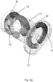
- the drum cam 11 preferably comprises two cam tracks 13 and 14 for the cam follower 12, as best shown in figure 9a , where the drum cam is shown in its entirety in axonometric view.
- mold 10 also consists of a mold bottom 8, required if a container with a concave bottom is molded, the generation of the cyclic translatory movement from top to bottom parallel to direction Z' and vice versa of the mold bottom 8 is achieved through a second cam 15 coupled to the cam follower 16, also translating in direction Z'.
- the disc cam 15 comprises at least one track for the cam follower 16, and it preferably comprises two tracks 17 and 18 generally but not necessarily of a different shape.
- the ascent movement of the mold bottom 8 is controlled by a rotation of the disc cam 15 in a clockwise direction about axis Y which returns it to the rest position K.
- each rotation being made about axis Y is also transmitted to the other cam by an angle of equal magnitude.
- the two cams can also be made in a single piece 11'.
- the cyclic opening motion of mold 10 is transmitted to the drum cam 11 by a servomotor 30.
- a servomotor 30 is also typically defined torque in English.
- the servomotor 30 also generates the motion of this disc cam 15.
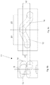
- the motion to the various parts making up mold 10 can be produced by a mechanical system consisting of at least one cam track 32, a lever 31 and a cam follower 33, integral with lever 31 and which interacts with the cam track 32.
- a variant embodiment can provide for cam 32 to have two different cam tracks that are followed by the same cam follower in the two operating positions defined in the design of the mold to obtain the same result as the embodiment shown above.
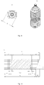
- Fig. 19 shows a graph of the cycle time advantage that the invention provides to a blow molding machine.
- This cycle time is the sum of:
- a cycle time for the production of a large container, such as for example the bottle shown in fig. 18 , in the graph of figure 19 is represented with the straight line B2.
- the maximum opening position of mold 10 is shown in figures 14 to 17 .
- the mold of the invention is used to produce a smaller container, such as a bottle of a shape similar to that in figure 18 but with smaller volume, and which requires a smaller maximum opening of the lateral half molds, as shown in figures 10 to 13 , it should be noted that the total cycle time indicated with T1 and represented by the straight line B1 is less than the cycle time T2. Since the time difference to perform the blowing step Tp1 does not differ much from step Tp2, depending in fact mainly on the type of material used to make the container, the cycle time reduction is accomplished by reducing the opening step time To1, and the closing step time Tc1 that are less than the times of the corresponding To2 and Tc2 by a value T4 and T3, respectively. Thanks to these time gains, there is a reduction in the cycle time of the mold equal to T5 whenever it is used to make containers of sizes smaller than those that are the maximum achievable with the mold itself.
Landscapes
- Engineering & Computer Science (AREA)
- Manufacturing & Machinery (AREA)
- Mechanical Engineering (AREA)
- Moulds For Moulding Plastics Or The Like (AREA)
- Blow-Moulding Or Thermoforming Of Plastics Or The Like (AREA)
Claims (10)
- Blasform (10) für Behälter aus thermoplastischem Material, aufweisend zwei Halbformen (1, 2) mit einer zyklischen Öffnungs- und Schließvorrichtung, die die beiden Halbformen zueinander und voneinander bewegt, wobei der Öffnungswinkel von 0° in der geschlossenen Position der Halbformen (1, 2) bis zu einem Maximalwert αmax reicht, bei dem die beiden Halbformen maximal geöffnet sind, eine Kurventrommel (11) mit einer ersten Kulisse (14), einem ersten Nocken (12) und Hebel (29) zur Übertragung der Öffnungs- und Schließbewegung der beiden Halbformen (1, 2), die durch die Bewegung des ersten Nockens (12) weitergeleitet werden, wobei der erste Nocken (12), der der ersten Kulisse (14) folgt, geeignet ist eine erste zyklische Öffnungs- und Schließbewegung der beiden Halbformen mit einem ersten maximalen Öffnungswinkel α1 zu erzeugen, so dass die Entnahme eines Behälters mit einem ersten von der Form vorgegebenen Durchmesser ermöglicht wird,
dadurch gekennzeichnet, dass die Kurventrommel (11) eine zweite Kulisse (13) aufweist, der der erste Nocken (12) alternativ zur ersten Kulisse (14) folgen kann, um eine zweite zyklische Öffnungs- und Schließbewegung der beiden Halbformen (1, 2) zu erzeugen, die einen zweiten maximalen Öffnungswinkel α2 erreicht, der größer ist als der erste maximale Öffnungswinkel α1, so dass die Entnahme eines Behälters mit größerem Durchmesser als der erste Durchmesser aus der Form ermöglicht wird. - Form gemäß Anspruch 1, aufweisend ein für die beiden Halbformen komplementäres Formenunterteil (8), das eine zyklische Öffnungs- und Schließbewegung der beiden Halbformen synchron mit der Bewegung der beiden Halbformen ausführen kann.
- Form gemäß Anspruch 2, aufweisend eine Kurvenscheibe (15), die integral an der Kurventrommel (11) befestigt ist und eine dritte Kulisse (17) und eine vierte Kulisse (18) zur Bewegung des Formenunterteils (8) einschließt, sowie mit einem zweiten Nocken (16), der geeignet ist, der dritten und vierten Kulisse (17, 18) in zwei verschiedenen alternativen Bewegungen zu folgen.
- Form gemäß Anspruch 3, wobei die dritte Kulisse (17) durch die Bewegung des zweiten Nockens (16) eine erste Verlagerung des Formenunterteils (8) mit vorgegebener Länge erzeugt, und die vierte Kulisse (18) durch die Bewegung des zweiten Nockens (16) eine zweite Verlagerung des Formenunterteils (8) mit einer anderen Länge als der ersten Länge erzeugt.
- Form gemäß Anspruch 3 oder 4, wobei die Kurventrommel (11) und die Kurvenscheibe (15) zusammen um eine gemeinsame Achse, senkrecht zur Scharnierachse der beiden Halbformen (1, 2), oszillieren können.
- Form gemäß einem der vorigen Ansprüche, wobei die Halbformen (1, 2) jeweils einen Formenhalter (3, 4) und eine Halbschale (5, 6) oder einen Formenhalter (3, 4), einen Schalenträger (5', 6') und eine Halbschale (5, 6) aufweisen.
- Form gemäß einem der Ansprüche 3 bis 6, wobei ein dritter Nocken (33) vorgesehen ist, der geeignet ist, einer fünften Kulisse (32) in einem ersten Arbeitszyklus zu folgen, um eine zyklische Winkelbewegung an die Kurventrommel (11) und die Kurvenscheibe (15) mit der Auslenkung β1 weiterzuleiten.
- Form gemäß Anspruch 7, wobei der dritte Nocken (33) am Ende eines Hebels (31) befestigt ist, der in verschiedenen Winkellagen positioniert ist und geeignet ist, der fünften Kulisse (32) in einem zweiten Arbeitszyklus nach dem ersten Arbeitszyklus zu folgen, um eine zyklische Winkelbewegung an die Kurventrommel (11) und die Kurvenscheibe (16) mit dem Wert β2 weiterzuleiten.
- Form gemäß dem vorigen Anspruch, wobei die Kurventrommel (11) und die Kurvenscheibe (15) aus einem einzigen Stück (11') hergestellt werden können.
- Rotationsblasmaschine, aufweisend eine Vielzahl von Formen mit den Merkmalen eines der vorigen Ansprüche.
Applications Claiming Priority (2)
| Application Number | Priority Date | Filing Date | Title |
|---|---|---|---|
| ITRM20140032 | 2014-01-22 | ||
| PCT/IB2015/050467 WO2015110970A1 (en) | 2014-01-22 | 2015-01-21 | Blowing mold for blowing thermoplastic material containers |
Publications (2)
| Publication Number | Publication Date |
|---|---|
| EP3102383A1 EP3102383A1 (de) | 2016-12-14 |
| EP3102383B1 true EP3102383B1 (de) | 2018-04-04 |
Family
ID=50391296
Family Applications (1)
| Application Number | Title | Priority Date | Filing Date |
|---|---|---|---|
| EP15708277.7A Active EP3102383B1 (de) | 2014-01-22 | 2015-01-21 | Blasform zum blasen von behältern aus thermoplastischem material |
Country Status (5)
| Country | Link |
|---|---|
| EP (1) | EP3102383B1 (de) |
| CN (1) | CN106170383B (de) |
| ES (1) | ES2674798T3 (de) |
| TR (1) | TR201809436T4 (de) |
| WO (1) | WO2015110970A1 (de) |
Families Citing this family (3)
| Publication number | Priority date | Publication date | Assignee | Title |
|---|---|---|---|---|
| DE102015117017A1 (de) * | 2015-10-06 | 2017-04-06 | Krones Ag | Vorrichtung und Verfahren zum Umformen von Kunststoffvorformlingen zu Kunststoffbehältnissen mit Kopplungseinrichtung |
| BG67402B1 (bg) * | 2019-04-19 | 2021-12-15 | "Индекс - 6" Оод | Задвижващ механизъм за формовъчна матрица |
| CN114654658A (zh) * | 2022-03-17 | 2022-06-24 | 杭州恒新塑业有限公司 | 一体式高分子包装容器成型设备 |
Family Cites Families (7)
| Publication number | Priority date | Publication date | Assignee | Title |
|---|---|---|---|---|
| FR2841495B1 (fr) * | 2002-06-27 | 2004-11-12 | Sidel Sa | Dispositif de moulage, par soufflage ou etirage-soufflage, de recipients en matiere thermoplastique |
| DE102005034541A1 (de) | 2005-07-23 | 2007-02-01 | Sig Technology Ltd. | Verfahren und Vorrichtung zur Blasformung von Behältern |
| DE102007022638A1 (de) * | 2007-05-15 | 2008-11-20 | Sig Technology Ag | Vorrichtung zur Blasformung von Behältern |
| DE102008029531A1 (de) * | 2008-06-21 | 2009-12-24 | Krones Ag | Verfahren und Vorrichtung zum Einsetzen eines Vorformlings in und zur Entnahme einer Flasche aus einer Blasmaschine |
| DE102009049260A1 (de) * | 2009-10-13 | 2011-04-21 | Krones Ag | Formträger mit Antriebseinrichtung |
| US8573963B2 (en) * | 2011-04-01 | 2013-11-05 | Graham Engineering Corporation | Adjustable multiple-piece cam track |
| CN103171130B (zh) * | 2013-03-19 | 2015-10-28 | 江苏新美星包装机械股份有限公司 | 一种单轴开合模、底模升降联动机构 |
-
2015
- 2015-01-21 EP EP15708277.7A patent/EP3102383B1/de active Active
- 2015-01-21 TR TR2018/09436T patent/TR201809436T4/tr unknown
- 2015-01-21 WO PCT/IB2015/050467 patent/WO2015110970A1/en not_active Ceased
- 2015-01-21 CN CN201580005351.4A patent/CN106170383B/zh active Active
- 2015-01-21 ES ES15708277.7T patent/ES2674798T3/es active Active
Also Published As
| Publication number | Publication date |
|---|---|
| CN106170383B (zh) | 2018-01-12 |
| EP3102383A1 (de) | 2016-12-14 |
| CN106170383A (zh) | 2016-11-30 |
| TR201809436T4 (tr) | 2018-07-23 |
| ES2674798T3 (es) | 2018-07-04 |
| WO2015110970A1 (en) | 2015-07-30 |
Similar Documents
| Publication | Publication Date | Title |
|---|---|---|
| EP3103615B1 (de) | Blas- oder streckblasmaschine für flaschen aus polymermaterial | |
| EP3200968B1 (de) | Formvorrichtung für behälter aus thermoplastischem material | |
| RU2201867C2 (ru) | Усовершенствование устройства для производства тары из термопластичных материалов | |
| EP2202047B1 (de) | Blasform mit Verrieglungsvorrichtung und das Verfahren | |
| US11033946B2 (en) | Actuator with variable speed servo motor for redraw assembly | |
| WO2015110970A1 (en) | Blowing mold for blowing thermoplastic material containers | |
| CN108290343B (zh) | 用于吹塑成型容器的设备 | |
| EP3307517B1 (de) | Blasform zum blasen von thermoplastischen kunststoffbehältern | |
| US20110117237A1 (en) | Mould Carrier with Drive | |
| EP3293156B1 (de) | Mündungsringhalter einer maschine zur herstellung von glasbehältern und dazu gehörendem verfahren | |
| EP4026682B1 (de) | Vorrichtung zum blasformen oder streckblasformen von flaschen | |
| EP3466641B1 (de) | Blasform und blasformvorrichtung | |
| EP4043182B1 (de) | Vorrichtung zum blasformen von behälter | |
| JP2018083673A (ja) | 処理システム及び処理方法 | |
| WO2018225734A1 (ja) | 金型 | |
| JPWO2020017505A1 (ja) | ブロー成形用金型、これを用いた樹脂製容器の製造方法および樹脂製の容器 | |
| EP1982822A1 (de) | Gerät zur Bildung eines Formnestes für eine Presse, insbesondere zur Herstellung von Kunststoffartikeln |
Legal Events
| Date | Code | Title | Description |
|---|---|---|---|
| STAA | Information on the status of an ep patent application or granted ep patent |
Free format text: STATUS: THE INTERNATIONAL PUBLICATION HAS BEEN MADE |
|
| PUAI | Public reference made under article 153(3) epc to a published international application that has entered the european phase |
Free format text: ORIGINAL CODE: 0009012 |
|
| STAA | Information on the status of an ep patent application or granted ep patent |
Free format text: STATUS: REQUEST FOR EXAMINATION WAS MADE |
|
| 17P | Request for examination filed |
Effective date: 20160818 |
|
| AK | Designated contracting states |
Kind code of ref document: A1 Designated state(s): AL AT BE BG CH CY CZ DE DK EE ES FI FR GB GR HR HU IE IS IT LI LT LU LV MC MK MT NL NO PL PT RO RS SE SI SK SM TR |
|
| AX | Request for extension of the european patent |
Extension state: BA ME |
|
| DAX | Request for extension of the european patent (deleted) | ||
| GRAP | Despatch of communication of intention to grant a patent |
Free format text: ORIGINAL CODE: EPIDOSNIGR1 |
|
| STAA | Information on the status of an ep patent application or granted ep patent |
Free format text: STATUS: GRANT OF PATENT IS INTENDED |
|
| INTG | Intention to grant announced |
Effective date: 20171025 |
|
| GRAS | Grant fee paid |
Free format text: ORIGINAL CODE: EPIDOSNIGR3 |
|
| GRAA | (expected) grant |
Free format text: ORIGINAL CODE: 0009210 |
|
| STAA | Information on the status of an ep patent application or granted ep patent |
Free format text: STATUS: THE PATENT HAS BEEN GRANTED |
|
| AK | Designated contracting states |
Kind code of ref document: B1 Designated state(s): AL AT BE BG CH CY CZ DE DK EE ES FI FR GB GR HR HU IE IS IT LI LT LU LV MC MK MT NL NO PL PT RO RS SE SI SK SM TR |
|
| REG | Reference to a national code |
Ref country code: GB Ref legal event code: FG4D |
|
| REG | Reference to a national code |
Ref country code: CH Ref legal event code: EP |
|
| REG | Reference to a national code |
Ref country code: AT Ref legal event code: REF Ref document number: 985134 Country of ref document: AT Kind code of ref document: T Effective date: 20180415 |
|
| REG | Reference to a national code |
Ref country code: IE Ref legal event code: FG4D |
|
| REG | Reference to a national code |
Ref country code: DE Ref legal event code: R096 Ref document number: 602015009567 Country of ref document: DE |
|
| REG | Reference to a national code |
Ref country code: ES Ref legal event code: FG2A Ref document number: 2674798 Country of ref document: ES Kind code of ref document: T3 Effective date: 20180704 |
|
| REG | Reference to a national code |
Ref country code: NL Ref legal event code: MP Effective date: 20180404 |
|
| REG | Reference to a national code |
Ref country code: LT Ref legal event code: MG4D |
|
| PG25 | Lapsed in a contracting state [announced via postgrant information from national office to epo] |
Ref country code: NL Free format text: LAPSE BECAUSE OF FAILURE TO SUBMIT A TRANSLATION OF THE DESCRIPTION OR TO PAY THE FEE WITHIN THE PRESCRIBED TIME-LIMIT Effective date: 20180404 |
|
| PG25 | Lapsed in a contracting state [announced via postgrant information from national office to epo] |
Ref country code: PL Free format text: LAPSE BECAUSE OF FAILURE TO SUBMIT A TRANSLATION OF THE DESCRIPTION OR TO PAY THE FEE WITHIN THE PRESCRIBED TIME-LIMIT Effective date: 20180404 Ref country code: FI Free format text: LAPSE BECAUSE OF FAILURE TO SUBMIT A TRANSLATION OF THE DESCRIPTION OR TO PAY THE FEE WITHIN THE PRESCRIBED TIME-LIMIT Effective date: 20180404 Ref country code: BG Free format text: LAPSE BECAUSE OF FAILURE TO SUBMIT A TRANSLATION OF THE DESCRIPTION OR TO PAY THE FEE WITHIN THE PRESCRIBED TIME-LIMIT Effective date: 20180704 Ref country code: LT Free format text: LAPSE BECAUSE OF FAILURE TO SUBMIT A TRANSLATION OF THE DESCRIPTION OR TO PAY THE FEE WITHIN THE PRESCRIBED TIME-LIMIT Effective date: 20180404 Ref country code: AL Free format text: LAPSE BECAUSE OF FAILURE TO SUBMIT A TRANSLATION OF THE DESCRIPTION OR TO PAY THE FEE WITHIN THE PRESCRIBED TIME-LIMIT Effective date: 20180404 Ref country code: SE Free format text: LAPSE BECAUSE OF FAILURE TO SUBMIT A TRANSLATION OF THE DESCRIPTION OR TO PAY THE FEE WITHIN THE PRESCRIBED TIME-LIMIT Effective date: 20180404 Ref country code: NO Free format text: LAPSE BECAUSE OF FAILURE TO SUBMIT A TRANSLATION OF THE DESCRIPTION OR TO PAY THE FEE WITHIN THE PRESCRIBED TIME-LIMIT Effective date: 20180704 |
|
| PG25 | Lapsed in a contracting state [announced via postgrant information from national office to epo] |
Ref country code: HR Free format text: LAPSE BECAUSE OF FAILURE TO SUBMIT A TRANSLATION OF THE DESCRIPTION OR TO PAY THE FEE WITHIN THE PRESCRIBED TIME-LIMIT Effective date: 20180404 Ref country code: LV Free format text: LAPSE BECAUSE OF FAILURE TO SUBMIT A TRANSLATION OF THE DESCRIPTION OR TO PAY THE FEE WITHIN THE PRESCRIBED TIME-LIMIT Effective date: 20180404 Ref country code: GR Free format text: LAPSE BECAUSE OF FAILURE TO SUBMIT A TRANSLATION OF THE DESCRIPTION OR TO PAY THE FEE WITHIN THE PRESCRIBED TIME-LIMIT Effective date: 20180705 Ref country code: RS Free format text: LAPSE BECAUSE OF FAILURE TO SUBMIT A TRANSLATION OF THE DESCRIPTION OR TO PAY THE FEE WITHIN THE PRESCRIBED TIME-LIMIT Effective date: 20180404 |
|
| PG25 | Lapsed in a contracting state [announced via postgrant information from national office to epo] |
Ref country code: PT Free format text: LAPSE BECAUSE OF FAILURE TO SUBMIT A TRANSLATION OF THE DESCRIPTION OR TO PAY THE FEE WITHIN THE PRESCRIBED TIME-LIMIT Effective date: 20180806 |
|
| REG | Reference to a national code |
Ref country code: DE Ref legal event code: R097 Ref document number: 602015009567 Country of ref document: DE |
|
| PG25 | Lapsed in a contracting state [announced via postgrant information from national office to epo] |
Ref country code: CZ Free format text: LAPSE BECAUSE OF FAILURE TO SUBMIT A TRANSLATION OF THE DESCRIPTION OR TO PAY THE FEE WITHIN THE PRESCRIBED TIME-LIMIT Effective date: 20180404 Ref country code: RO Free format text: LAPSE BECAUSE OF FAILURE TO SUBMIT A TRANSLATION OF THE DESCRIPTION OR TO PAY THE FEE WITHIN THE PRESCRIBED TIME-LIMIT Effective date: 20180404 Ref country code: SK Free format text: LAPSE BECAUSE OF FAILURE TO SUBMIT A TRANSLATION OF THE DESCRIPTION OR TO PAY THE FEE WITHIN THE PRESCRIBED TIME-LIMIT Effective date: 20180404 Ref country code: EE Free format text: LAPSE BECAUSE OF FAILURE TO SUBMIT A TRANSLATION OF THE DESCRIPTION OR TO PAY THE FEE WITHIN THE PRESCRIBED TIME-LIMIT Effective date: 20180404 Ref country code: DK Free format text: LAPSE BECAUSE OF FAILURE TO SUBMIT A TRANSLATION OF THE DESCRIPTION OR TO PAY THE FEE WITHIN THE PRESCRIBED TIME-LIMIT Effective date: 20180404 |
|
| PLBE | No opposition filed within time limit |
Free format text: ORIGINAL CODE: 0009261 |
|
| STAA | Information on the status of an ep patent application or granted ep patent |
Free format text: STATUS: NO OPPOSITION FILED WITHIN TIME LIMIT |
|
| PG25 | Lapsed in a contracting state [announced via postgrant information from national office to epo] |
Ref country code: SM Free format text: LAPSE BECAUSE OF FAILURE TO SUBMIT A TRANSLATION OF THE DESCRIPTION OR TO PAY THE FEE WITHIN THE PRESCRIBED TIME-LIMIT Effective date: 20180404 |
|
| 26N | No opposition filed |
Effective date: 20190107 |
|
| PG25 | Lapsed in a contracting state [announced via postgrant information from national office to epo] |
Ref country code: SI Free format text: LAPSE BECAUSE OF FAILURE TO SUBMIT A TRANSLATION OF THE DESCRIPTION OR TO PAY THE FEE WITHIN THE PRESCRIBED TIME-LIMIT Effective date: 20180404 |
|
| PG25 | Lapsed in a contracting state [announced via postgrant information from national office to epo] |
Ref country code: MC Free format text: LAPSE BECAUSE OF FAILURE TO SUBMIT A TRANSLATION OF THE DESCRIPTION OR TO PAY THE FEE WITHIN THE PRESCRIBED TIME-LIMIT Effective date: 20180404 |
|
| REG | Reference to a national code |
Ref country code: CH Ref legal event code: PL |
|
| GBPC | Gb: european patent ceased through non-payment of renewal fee |
Effective date: 20190121 |
|
| PG25 | Lapsed in a contracting state [announced via postgrant information from national office to epo] |
Ref country code: LU Free format text: LAPSE BECAUSE OF NON-PAYMENT OF DUE FEES Effective date: 20190121 |
|
| REG | Reference to a national code |
Ref country code: BE Ref legal event code: MM Effective date: 20190131 |
|
| REG | Reference to a national code |
Ref country code: IE Ref legal event code: MM4A |
|
| PG25 | Lapsed in a contracting state [announced via postgrant information from national office to epo] |
Ref country code: BE Free format text: LAPSE BECAUSE OF NON-PAYMENT OF DUE FEES Effective date: 20190131 |
|
| PG25 | Lapsed in a contracting state [announced via postgrant information from national office to epo] |
Ref country code: GB Free format text: LAPSE BECAUSE OF NON-PAYMENT OF DUE FEES Effective date: 20190121 Ref country code: LI Free format text: LAPSE BECAUSE OF NON-PAYMENT OF DUE FEES Effective date: 20190131 Ref country code: CH Free format text: LAPSE BECAUSE OF NON-PAYMENT OF DUE FEES Effective date: 20190131 |
|
| PG25 | Lapsed in a contracting state [announced via postgrant information from national office to epo] |
Ref country code: IE Free format text: LAPSE BECAUSE OF NON-PAYMENT OF DUE FEES Effective date: 20190121 |
|
| PG25 | Lapsed in a contracting state [announced via postgrant information from national office to epo] |
Ref country code: MT Free format text: LAPSE BECAUSE OF NON-PAYMENT OF DUE FEES Effective date: 20190121 |
|
| PG25 | Lapsed in a contracting state [announced via postgrant information from national office to epo] |
Ref country code: CY Free format text: LAPSE BECAUSE OF FAILURE TO SUBMIT A TRANSLATION OF THE DESCRIPTION OR TO PAY THE FEE WITHIN THE PRESCRIBED TIME-LIMIT Effective date: 20180404 |
|
| PG25 | Lapsed in a contracting state [announced via postgrant information from national office to epo] |
Ref country code: IS Free format text: LAPSE BECAUSE OF FAILURE TO SUBMIT A TRANSLATION OF THE DESCRIPTION OR TO PAY THE FEE WITHIN THE PRESCRIBED TIME-LIMIT Effective date: 20180804 |
|
| PG25 | Lapsed in a contracting state [announced via postgrant information from national office to epo] |
Ref country code: HU Free format text: LAPSE BECAUSE OF FAILURE TO SUBMIT A TRANSLATION OF THE DESCRIPTION OR TO PAY THE FEE WITHIN THE PRESCRIBED TIME-LIMIT; INVALID AB INITIO Effective date: 20150121 |
|
| REG | Reference to a national code |
Ref country code: AT Ref legal event code: UEP Ref document number: 985134 Country of ref document: AT Kind code of ref document: T Effective date: 20180404 |
|
| PG25 | Lapsed in a contracting state [announced via postgrant information from national office to epo] |
Ref country code: MK Free format text: LAPSE BECAUSE OF FAILURE TO SUBMIT A TRANSLATION OF THE DESCRIPTION OR TO PAY THE FEE WITHIN THE PRESCRIBED TIME-LIMIT Effective date: 20180404 |
|
| P01 | Opt-out of the competence of the unified patent court (upc) registered |
Effective date: 20230525 |
|
| PGFP | Annual fee paid to national office [announced via postgrant information from national office to epo] |
Ref country code: ES Payment date: 20250226 Year of fee payment: 11 |
|
| PGFP | Annual fee paid to national office [announced via postgrant information from national office to epo] |
Ref country code: AT Payment date: 20250122 Year of fee payment: 11 |
|
| PGFP | Annual fee paid to national office [announced via postgrant information from national office to epo] |
Ref country code: TR Payment date: 20250113 Year of fee payment: 11 |
|
| PGFP | Annual fee paid to national office [announced via postgrant information from national office to epo] |
Ref country code: DE Payment date: 20260121 Year of fee payment: 12 |
|
| PGFP | Annual fee paid to national office [announced via postgrant information from national office to epo] |
Ref country code: IT Payment date: 20260129 Year of fee payment: 12 |
|
| PGFP | Annual fee paid to national office [announced via postgrant information from national office to epo] |
Ref country code: FR Payment date: 20260123 Year of fee payment: 12 |