EP3102384B1 - Procédé et dispositif d'équilibrage de la température de préformes - Google Patents
Procédé et dispositif d'équilibrage de la température de préformes Download PDFInfo
- Publication number
- EP3102384B1 EP3102384B1 EP15718444.1A EP15718444A EP3102384B1 EP 3102384 B1 EP3102384 B1 EP 3102384B1 EP 15718444 A EP15718444 A EP 15718444A EP 3102384 B1 EP3102384 B1 EP 3102384B1
- Authority
- EP
- European Patent Office
- Prior art keywords
- heating
- preforms
- accordance
- amount
- control
- Prior art date
- Legal status (The legal status is an assumption and is not a legal conclusion. Google has not performed a legal analysis and makes no representation as to the accuracy of the status listed.)
- Active
Links
Images



Classifications
-
- B—PERFORMING OPERATIONS; TRANSPORTING
- B29—WORKING OF PLASTICS; WORKING OF SUBSTANCES IN A PLASTIC STATE IN GENERAL
- B29C—SHAPING OR JOINING OF PLASTICS; SHAPING OF MATERIAL IN A PLASTIC STATE, NOT OTHERWISE PROVIDED FOR; AFTER-TREATMENT OF THE SHAPED PRODUCTS, e.g. REPAIRING
- B29C49/00—Blow-moulding, i.e. blowing a preform or parison to a desired shape within a mould; Apparatus therefor
- B29C49/42—Component parts, details or accessories; Auxiliary operations
- B29C49/64—Heating or cooling preforms, parisons or blown articles
- B29C49/6409—Thermal conditioning of preforms
-
- B—PERFORMING OPERATIONS; TRANSPORTING
- B29—WORKING OF PLASTICS; WORKING OF SUBSTANCES IN A PLASTIC STATE IN GENERAL
- B29C—SHAPING OR JOINING OF PLASTICS; SHAPING OF MATERIAL IN A PLASTIC STATE, NOT OTHERWISE PROVIDED FOR; AFTER-TREATMENT OF THE SHAPED PRODUCTS, e.g. REPAIRING
- B29C49/00—Blow-moulding, i.e. blowing a preform or parison to a desired shape within a mould; Apparatus therefor
- B29C49/42—Component parts, details or accessories; Auxiliary operations
- B29C49/64—Heating or cooling preforms, parisons or blown articles
-
- B—PERFORMING OPERATIONS; TRANSPORTING
- B29—WORKING OF PLASTICS; WORKING OF SUBSTANCES IN A PLASTIC STATE IN GENERAL
- B29C—SHAPING OR JOINING OF PLASTICS; SHAPING OF MATERIAL IN A PLASTIC STATE, NOT OTHERWISE PROVIDED FOR; AFTER-TREATMENT OF THE SHAPED PRODUCTS, e.g. REPAIRING
- B29C49/00—Blow-moulding, i.e. blowing a preform or parison to a desired shape within a mould; Apparatus therefor
- B29C49/42—Component parts, details or accessories; Auxiliary operations
- B29C49/64—Heating or cooling preforms, parisons or blown articles
- B29C49/6409—Thermal conditioning of preforms
- B29C49/6418—Heating of preforms
-
- B—PERFORMING OPERATIONS; TRANSPORTING
- B29—WORKING OF PLASTICS; WORKING OF SUBSTANCES IN A PLASTIC STATE IN GENERAL
- B29C—SHAPING OR JOINING OF PLASTICS; SHAPING OF MATERIAL IN A PLASTIC STATE, NOT OTHERWISE PROVIDED FOR; AFTER-TREATMENT OF THE SHAPED PRODUCTS, e.g. REPAIRING
- B29C49/00—Blow-moulding, i.e. blowing a preform or parison to a desired shape within a mould; Apparatus therefor
- B29C49/42—Component parts, details or accessories; Auxiliary operations
- B29C49/64—Heating or cooling preforms, parisons or blown articles
- B29C49/68—Ovens specially adapted for heating preforms or parisons
- B29C49/6835—Ovens specially adapted for heating preforms or parisons using reflectors
-
- B—PERFORMING OPERATIONS; TRANSPORTING
- B29—WORKING OF PLASTICS; WORKING OF SUBSTANCES IN A PLASTIC STATE IN GENERAL
- B29C—SHAPING OR JOINING OF PLASTICS; SHAPING OF MATERIAL IN A PLASTIC STATE, NOT OTHERWISE PROVIDED FOR; AFTER-TREATMENT OF THE SHAPED PRODUCTS, e.g. REPAIRING
- B29C49/00—Blow-moulding, i.e. blowing a preform or parison to a desired shape within a mould; Apparatus therefor
- B29C49/42—Component parts, details or accessories; Auxiliary operations
- B29C49/64—Heating or cooling preforms, parisons or blown articles
- B29C49/68—Ovens specially adapted for heating preforms or parisons
- B29C49/685—Rotating the preform in relation to heating means
-
- B—PERFORMING OPERATIONS; TRANSPORTING
- B29—WORKING OF PLASTICS; WORKING OF SUBSTANCES IN A PLASTIC STATE IN GENERAL
- B29C—SHAPING OR JOINING OF PLASTICS; SHAPING OF MATERIAL IN A PLASTIC STATE, NOT OTHERWISE PROVIDED FOR; AFTER-TREATMENT OF THE SHAPED PRODUCTS, e.g. REPAIRING
- B29C49/00—Blow-moulding, i.e. blowing a preform or parison to a desired shape within a mould; Apparatus therefor
- B29C49/42—Component parts, details or accessories; Auxiliary operations
- B29C49/78—Measuring, controlling or regulating
-
- B—PERFORMING OPERATIONS; TRANSPORTING
- B29—WORKING OF PLASTICS; WORKING OF SUBSTANCES IN A PLASTIC STATE IN GENERAL
- B29C—SHAPING OR JOINING OF PLASTICS; SHAPING OF MATERIAL IN A PLASTIC STATE, NOT OTHERWISE PROVIDED FOR; AFTER-TREATMENT OF THE SHAPED PRODUCTS, e.g. REPAIRING
- B29C49/00—Blow-moulding, i.e. blowing a preform or parison to a desired shape within a mould; Apparatus therefor
- B29C49/42—Component parts, details or accessories; Auxiliary operations
- B29C49/78—Measuring, controlling or regulating
- B29C49/786—Temperature
-
- B—PERFORMING OPERATIONS; TRANSPORTING
- B29—WORKING OF PLASTICS; WORKING OF SUBSTANCES IN A PLASTIC STATE IN GENERAL
- B29C—SHAPING OR JOINING OF PLASTICS; SHAPING OF MATERIAL IN A PLASTIC STATE, NOT OTHERWISE PROVIDED FOR; AFTER-TREATMENT OF THE SHAPED PRODUCTS, e.g. REPAIRING
- B29C49/00—Blow-moulding, i.e. blowing a preform or parison to a desired shape within a mould; Apparatus therefor
- B29C49/42—Component parts, details or accessories; Auxiliary operations
- B29C49/78—Measuring, controlling or regulating
- B29C49/786—Temperature
- B29C2049/7861—Temperature of the preform
- B29C2049/7862—Temperature of the preform characterised by temperature values or ranges
-
- B—PERFORMING OPERATIONS; TRANSPORTING
- B29—WORKING OF PLASTICS; WORKING OF SUBSTANCES IN A PLASTIC STATE IN GENERAL
- B29C—SHAPING OR JOINING OF PLASTICS; SHAPING OF MATERIAL IN A PLASTIC STATE, NOT OTHERWISE PROVIDED FOR; AFTER-TREATMENT OF THE SHAPED PRODUCTS, e.g. REPAIRING
- B29C49/00—Blow-moulding, i.e. blowing a preform or parison to a desired shape within a mould; Apparatus therefor
- B29C49/42—Component parts, details or accessories; Auxiliary operations
- B29C49/78—Measuring, controlling or regulating
- B29C49/786—Temperature
- B29C2049/7867—Temperature of the heating or cooling means
-
- B—PERFORMING OPERATIONS; TRANSPORTING
- B29—WORKING OF PLASTICS; WORKING OF SUBSTANCES IN A PLASTIC STATE IN GENERAL
- B29C—SHAPING OR JOINING OF PLASTICS; SHAPING OF MATERIAL IN A PLASTIC STATE, NOT OTHERWISE PROVIDED FOR; AFTER-TREATMENT OF THE SHAPED PRODUCTS, e.g. REPAIRING
- B29C2949/00—Indexing scheme relating to blow-moulding
- B29C2949/07—Preforms or parisons characterised by their configuration
- B29C2949/0715—Preforms or parisons characterised by their configuration the preform having one end closed
-
- B—PERFORMING OPERATIONS; TRANSPORTING
- B29—WORKING OF PLASTICS; WORKING OF SUBSTANCES IN A PLASTIC STATE IN GENERAL
- B29C—SHAPING OR JOINING OF PLASTICS; SHAPING OF MATERIAL IN A PLASTIC STATE, NOT OTHERWISE PROVIDED FOR; AFTER-TREATMENT OF THE SHAPED PRODUCTS, e.g. REPAIRING
- B29C49/00—Blow-moulding, i.e. blowing a preform or parison to a desired shape within a mould; Apparatus therefor
- B29C49/02—Combined blow-moulding and manufacture of the preform or the parison
- B29C49/06—Injection blow-moulding
-
- B—PERFORMING OPERATIONS; TRANSPORTING
- B29—WORKING OF PLASTICS; WORKING OF SUBSTANCES IN A PLASTIC STATE IN GENERAL
- B29C—SHAPING OR JOINING OF PLASTICS; SHAPING OF MATERIAL IN A PLASTIC STATE, NOT OTHERWISE PROVIDED FOR; AFTER-TREATMENT OF THE SHAPED PRODUCTS, e.g. REPAIRING
- B29C49/00—Blow-moulding, i.e. blowing a preform or parison to a desired shape within a mould; Apparatus therefor
- B29C49/28—Blow-moulding apparatus
- B29C49/28008—Blow-moulding apparatus mounting, exchanging or centering machine parts, e.g. modular parts
-
- B—PERFORMING OPERATIONS; TRANSPORTING
- B29—WORKING OF PLASTICS; WORKING OF SUBSTANCES IN A PLASTIC STATE IN GENERAL
- B29C—SHAPING OR JOINING OF PLASTICS; SHAPING OF MATERIAL IN A PLASTIC STATE, NOT OTHERWISE PROVIDED FOR; AFTER-TREATMENT OF THE SHAPED PRODUCTS, e.g. REPAIRING
- B29C49/00—Blow-moulding, i.e. blowing a preform or parison to a desired shape within a mould; Apparatus therefor
- B29C49/42—Component parts, details or accessories; Auxiliary operations
- B29C49/64—Heating or cooling preforms, parisons or blown articles
- B29C49/68—Ovens specially adapted for heating preforms or parisons
- B29C49/6845—Ovens specially adapted for heating preforms or parisons using ventilation, e.g. a fan
-
- B—PERFORMING OPERATIONS; TRANSPORTING
- B29—WORKING OF PLASTICS; WORKING OF SUBSTANCES IN A PLASTIC STATE IN GENERAL
- B29K—INDEXING SCHEME ASSOCIATED WITH SUBCLASSES B29B, B29C OR B29D, RELATING TO MOULDING MATERIALS OR TO MATERIALS FOR MOULDS, REINFORCEMENTS, FILLERS OR PREFORMED PARTS, e.g. INSERTS
- B29K2067/00—Use of polyesters or derivatives thereof, as moulding material
- B29K2067/003—PET, i.e. poylethylene terephthalate
Definitions
- the invention relates to a method and a device for tempering preforms in a blow molding machine with a heating channel having reflective walls, which is formed by a heating box. Through this heating channel, the preforms are passed to the blow molding temperature for the purpose of tempering.
- the heating box has heating means for heating the preforms.
- the heating box on a cooling device, which has at least one fan.
- the cooling device is used to cool the reflective walls of the heating channel by means of a flowing only outside of the heating channel along the walls along the amount of air, the heating power of the heating means is adjustable.
- the object of such methods and devices is to bring the preforms, which are usually produced in an injection molding process for the subsequent step of blow molding to the correct temperature.
- This temperature is e.g. for PET at about 120 ° and must be maintained in a narrow corridor to avoid material changes due to overstretching or phase transitions of the material.
- the preforms are also given a specific temperature profile.
- the preforms are heated, for example, by radiant heat from radiant heaters. It is preferred to use IR emitters and / or NIR emitters. Radiation that passes between the preforms or radiation that is not absorbed when passing through the preform is thereby reflected by the reflective walls of the heating channels to increase the efficiency of the heating boxes and to enhance depth heating in the preform material. This inevitably also heat up the reflective walls of the heating channels.
- the walls of the heating channels are usually made of aluminum materials which are highly reflective in the IR and / or NIR range, but these tend to corrode at temperatures above 180 ° and therefore have to be cooled.
- the preforms during transport through the heating section which is formed for example by several in the transport direction successively arranged heating channels, are supplied with cooling air, which is added through openings in the walls.
- a heater of a blow molding machine shows the US2011 / 0300497 A1 .
- the cooling air discharged in the direction of the preforms primarily causes the preforms to cool, which is also the purpose of the cooling. Air flowing past the preforms also acts on the walls of the radiant heater, thereby causing it to cool.
- the heating power of the radiant heater and the cooling air power are fixed to achieve a desired temperature profile of the preforms.
- the EP 2 380 719 A2 shows a comparable prior art.
- the desired temperature profile of the preforms is achieved by the corresponding setting of the radiant heater.
- An active cooling of the preforms in the area to be tempered is usually not required, so that no cooling air must be discharged into the heating channel for this purpose.
- Such a state of the art shows eg the WO 02/087850 , wherein the heating power and cooling capacity are independently adjustable to achieve a substantially constant surface temperature of the preforms.
- the EP 2 380 719 A2 discloses a method according to the preamble of claim 1 and an apparatus according to the preamble of claim 11.
- the reflective walls are generally cooled by passing cooling air past it.
- the cooling is adjusted so that at maximum heat output of the radiant heater, the critical temperature is not reached. It is known to adjust the cooling capacity manually if necessary.
- the heating power of the heating means of the heating channel must be adjustable. It is regulated in the prior art, for example, depending on different parameters. or controlled. During operation of the blow molding machine, never all heating means are set to maximum power. However, since the previously known cooling devices are designed and operated in such a way that overheating of the reflective walls is prevented in any case, that is to say even in the case of maximum heating power, the cooling capacity for the heating power actually applied in engine operation is oversized.
- This object is achieved according to the invention by a method according to claim 1 and by an apparatus according to claim 11.
- This method and apparatus is further developed in that a control device is provided which is designed to reduce the cooling power applied by the cooling device, e.g. To control the controlled amount of air in cooling air, depending on the respective heating power of the heating means of the heating channel or regulate.
- this heating power can be detected, for example, and fed to the control device as a measured variable.
- each heating box has its own cooling device and / or its own control device.
- Such a heating box with integrated cooling and / or control could be referred to as a heating module and has a more complex structure compared to conventional heating boxes, which had no integrated cooling device and no complex control.
- it is also possible to previously conventional heating boxes use and to associate with an associated cooling device and an associated control device.
- These associated cooling and / or control devices can also be assigned simultaneously to several conventional heating boxes. All of these variants are the subject of the claimed invention.
- the neck region is used to fix the preform during the blow molding step and to prevent undesirable deformation, it usually needs to be protected from overheating during thermal conditioning of the preform.
- the heat radiation emitted in the heating channel is shielded by diaphragms from the neck region of the preforms.
- part of the cooling power applied by the cooling device e.g. a portion of the amount of air delivered used to cool the neck region of the preforms, e.g. Cooling air along this led.
- temperature sensors are provided for monitoring the temperature of the reflective walls and / or the neck regions of the preforms. These temperature sensors allow the monitoring of the respective temperatures and thus can contribute to achieve a more precise control or regulation of the cooling performance and a disadvantageous overheating of the walls and / or the neck region of the preforms with reduced cooling capacity.
- the cooling device for this purpose comprises e.g. at least one fan having a variable speed motor.
- a speed-controlled fan as a result enables, in particular, a direct, reproducible and linear adjustment of the delivered air quantity.
- the cooling device has at least one throttle valve influencing the delivered amount of cooling air.
- a throttle which in particular as automatically controlled Throttle can be carried out, the delivered amount of air can be very easy setting.
- the control device is designed to set the delivered air quantity according to a preset characteristic as a function of the respective heating power of the heating box.
- a preset characteristic curve is understood to mean, in particular, that a defined amount of delivered air is preset for each adjustable heating power of the heating system.
- a control device designed in this way can be constructed particularly simply.
- a plurality of separately controllable heating boxes are provided with heating means in the method or in the device, form a plurality of Schukanäle the heating path for the preforms, and the control device is designed to the amount of air delivered according to a preset characteristic field depending on the respective Adjust heating capacities of the heating means of the individual heating boxes.
- a plurality of heating boxes form the heating section, which can be controlled separately. In doing so, e.g. not all heaters operated at the same power. It can e.g. Also, individual boilers are reduced in performance or completely or partially shut down while other boilers are operated at high or full power.
- a specific characteristic curve of the characteristic field is selected, from which the air quantity to be conveyed or the cooling capacity to be applied is then determined based on the adjusted total heating power.
- control device is designed to increase the amount of air delivered when the temperatures of the reflective walls and / or neck areas of the preforms are above predetermined critical temperatures, respectively.
- control device such that a transition to a characteristic characteristic of a lower cooling capacity takes place until a preset critical limit temperature is reached.
- the characteristic curves can be selected such that the conveyed air quantities determined according to the characteristic curves are sufficiently large to keep the wall temperature and / or the wet temperature below the predetermined critical temperatures.
- the cooling capacity or the delivered air quantity can then be reduced stepwise or continuously until the critical temperatures are reached.
- the predetermined critical temperatures are preferably selected such that a sufficient safety buffer still remains in relation to the temperatures at which negative effects are to be expected.
- control device can control the cooling capacity, e.g. increase the volume of air delivered, again until the critical temperatures have fallen below again.
- the basic structure of a device for forming preforms 1 in container 2 is in the Fig. 1 and in Fig. 2 shown.
- the device for forming the container 2 consists essentially of a blowing station 3, which is provided with a blow mold 4, in which a preform 1 can be inserted.
- the preform 1 may be an injection-molded part of polyethylene terephthalate (PET) without loss of generality. However, other suitable thermoplastic materials are known from which the preform may consist.
- PET polyethylene terephthalate
- the blow mold 4 consists of mold halves 5, 6 and a bottom part 7 which can be positioned by a lifting device 8.
- the preform 1 may be held in the region of the blowing station 3 by a transporting mandrel 9 which, together with the preform 1, passes through a plurality of treatment stations within the device. But it is also possible to use the preform 1, for example via pliers or other handling means directly into the blow mold 4.
- a connecting piston 10 is arranged below the transport mandrel, which feeds the preform 1 compressed air and at the same time makes a seal relative to the transport mandrel 9.
- a connecting piston 10 is arranged below the transport mandrel, which feeds the preform 1 compressed air and at the same time makes a seal relative to the transport mandrel 9.
- a stretching of the preform 1 takes place in this embodiment by means of a stretch rod 11 which is positioned by a cylinder 12.
- a mechanical positioning of the stretch rod 11 is carried out via curve segments, which are acted upon by Abgriffrollen.
- the use of curve segments is particularly useful when a plurality of blowing stations 3 is arranged on a rotating blowing wheel.
- the stretching system is designed such that a tandem arrangement of two cylinders 12 is provided. From a primary cylinder 13, the stretch rod 11 is first moved into the region of a bottom 14 of the preform 1 before the beginning of the actual stretching process.
- the primary cylinder 13 is positioned with extended stretch rod together with a carriage 15 carrying the primary cylinder 13 of a secondary cylinder 16 or via a cam control.
- the secondary cylinder 16 in such a cam-controlled manner that a current stretching position is predetermined by a guide roller 17 which slides along a curved path during the execution of the stretching operation.
- the guide roller 17 is pressed against the guideway by the secondary cylinder 16.
- the carriage 15 slides along two guide elements 18th
- Fig. 2 In addition to the blown container 2, the preform 1 is also shown in dashed lines and schematically a developing container bladder 23.
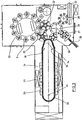
- Fig. 3 shows the basic structure of a blow molding machine, which is provided with a heating section 24 and a rotating blowing wheel 25. Starting from a preform input 26, the preforms 1 are transported by transfer wheels 27, 28, 29 into the region of the heating section 24.
- heating boxes 30 and blower 31 are arranged to temper the preforms 1. After a sufficient temperature control of the preforms 1, they are transferred to the blowing wheel 25, in the region of which blowing stations 3 are arranged.
- the finished blown container 2 are supplied by a further transfer wheels 32 a discharge path.
- special process steps must be taken in the heating and orientation of the preforms 1 become.
- advantageous effects can be achieved by adhering to special dimensioning regulations.
- thermoplastic material different plastics can be used.
- PET, PEN or PP can be used.
- the expansion of the preform 1 during the orientation process is carried out by compressed air supply.
- the compressed air supply is in a Vorblasphase in which gas, for example, compressed air, is supplied at a low pressure level and divided into a subsequent Hauptblasphase in which gas is supplied at a higher pressure level.
- compressed air is typically pressurized Interval of 10 bar to 25 bar used and during the main blowing phase compressed air is supplied with a pressure in the interval from 25 bar to 40 bar.
- the heating section 24 is formed of a plurality of rotating transport elements 33, which are lined up like a chain and guided along guide wheels 34. In particular, it is thought to open up a substantially rectangular basic contour by the chain-like arrangement.
- the arrangement shown to be particularly useful since in the region of the corresponding extent of the heating section 24 three pulleys 34,36 are positioned, in each case the smaller pulleys 36 in the area the transition to the linear curves of the heating section 24 and the larger deflection 34 in the immediate transfer area to the transfer wheel 29 and the input wheel 35.
- chain-like transport elements 33 it is also possible, for example, to use a rotating heating.
- the heating section 24 usually has one or more heating boxes 30, which form a closed heating channel 50.
- FIG. 4 is a heating box 30 with trained heating channel 50 shown schematically in cross section.
- the heating box 30 has reflective walls 51 which surround the heating channel 50.
- a plurality of radiant heaters 39 are arranged one above the other in the vertical direction, the heating radiation in the heating channel 50 in the direction of passing through the heating channel 50 passing preform 1.
- the wall 51 has reflecting structures 52, which correspond to those of the Radiators emit 39 emitted in vorformlingsabgewandte direction radiation evenly into the interior of the heating channel 50, for example, around the radiant heater 39 around.
- the preforms 1 are conveyed through the heating box 30 by means of transport elements 33.
- a cooling device 52 which comprises a fan 53 and an air box 54.
- the fan 53 is driven by a variable speed motor 55.
- the air delivered by the fan 53 flows through the air box 54 along the walls 51 and cools them. Part of the air conveyed by the blower 53 is guided by deflecting means 56 onto the neck region 57 of the preforms 1 in order to cool them.
- a plurality of temperature sensors 58, 59, 60, 61 are arranged.
- the sensor 58 is used as a radiation thermometer, e.g. as a pyrometer, to measure the temperature of the neck region 57 of the preform 1 executed.
- the sensors 59, 60 and 61 are designed to measure the temperature of the wall 51 of the heating channel 50.
- the sensor 59 is, for example, a PT100 sensor for linear measurement of the wall temperature, while the sensors 60 and 61 are designed as simple bimetallic switches.
- the signals of the temperature sensors 58, 59, 60, 61 are supplied to a control device 62.
- the heating power of the radiant heater 39 is adjusted by a system controller 63 and transmitted to the control device 62.
- the system control also determines the power distribution between the individual radiant heaters arranged at different height levels and between a plurality of heating boxes 30 arranged along the heating section 24.
- the control device 62 Based on the set heating power or heating power distribution of the radiant heater 39, the control device 62 adjusts the amount of air delivered by the cooling device 52. For this purpose, the control device 62 changes the speed of the motor 55.
- the cooling device 51 is the fan 53, a controllable throttle valve 64 downstream, via which regulates the amount of air delivered becomes.
- alternative actuators should be provided to achieve the desired cooling performance adjustment.
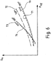
- FIG. 6 a characteristic field is shown. It is plotted the delivered air volume Q K over the heating power P HZ . For each characteristic curve, a certain amount of cooling air is assigned to a certain amount of cooling air.
- a first solid line 70 shows the amount of air needed at different heat outputs to maintain the temperature of the walls 51 at the critical temperature, which is about 180 ° C in conventional aluminum materials.
- a first dashed line 71 shows the amount of air required to keep the temperature slightly below the critical temperature for the same heat output, e.g. at 175 ° C.
- a dash-dotted line 72 shows an amount of air at which the temperature is farther from the critical point, e.g. at 160 ° C.
- an air quantity according to the characteristic curve 72 is initially set by the control device 62, and the temperatures which arise are detected by means of the temperature sensors 58, 59, 60. As long as a critical temperature is not reached, the amount of air is slowly reduced by the controller 62, whereby the detected temperatures increase. As soon as the temperatures of the wall 61 and / or the neck region 57 of the preforms 1 approach their critical value too much, the currently set air quantity is kept constant or increased again.
- the monitoring of the critical temperature of the wall 51 is realized by means of simple bimetallic switches 60, 61.
- the bimetallic switch 60 is dimensioned to switch at a temperature still below the critical temperature, e.g. at 175 ° C. As long as the bimetallic switch 60 is closed, the controller 62 can further reduce the amount of air. Once the bimetal switch 60 reaches its switching temperature and opens, the amount of air must be maintained.
- the bimetal switch 61 is set to the actual critical temperature of the wall 51, e.g. to 180 ° C and causes an emergency shutdown as soon as it reaches its switching temperature and thus detects a malfunction of the control device 62.
- the monitoring of the critical temperature of the neck region 57 of the preforms 1 takes place via the radiation thermometer 58.
- the characteristic curves 70, 71, 72, 73, 74 form a characteristic field, by means of which the control device 62 determines the respective cooling capacity to be applied by the cooling device, e.g. the required amount of cooling air.
- the individual characteristic curves 70, 71, 72, 73, 74 can be determined empirically, for example during the startup of a blow molding machine, and then stored in the control device 62. However, they can also be pre-set at the factory when the machine is delivered.
Landscapes
- Engineering & Computer Science (AREA)
- Manufacturing & Machinery (AREA)
- Mechanical Engineering (AREA)
- Physics & Mathematics (AREA)
- Thermal Sciences (AREA)
- Blow-Moulding Or Thermoforming Of Plastics Or The Like (AREA)
Claims (12)
- Procédé d'équilibrage de la température de préformes (1) dans une machine de moulage par soufflage, dans le cadre duquel au moins un caisson chauffant (30) doté de parois réfléchissantes (51) est placé le long d'un parcours de transport des préformes (1) pour former un canal de chauffage (50) que traversent les préformes, le caisson chauffant (30) présentant des moyens de chauffage (39) pour le réchauffement des préformes (1) dans le canal de chauffage (50) ainsi qu'au moins un dispositif de refroidissement (52) doté d'une soufflerie pour le refroidissement des parois réfléchissantes (51) du canal de chauffage (50), le refroidissement des parois étant assuré au moyen d'un courant d'air s'écoulant à l'extérieur du canal de chauffage (50) le long des parois (51) et la puissance de chauffage des moyens de chauffage (39) du canal de chauffage (50) étant réglable, caractérisé en ce qu'est prévu un dispositif de commande (62) techniquement conçu pour commander ou régler la puissance de refroidissement fournie par le dispositif de refroidissement (52), notamment son débit d'air, en fonction de la puissance de chauffage des moyens de chauffage (39) du canal de chauffage (50), notamment en fonction d'une mesure de la puissance de chauffage.
- Procédé selon la revendication 1, caractérisé en ce que plusieurs caissons chauffants (30) sont agencés les uns derrières les autres le long du parcours de transport dans le sens du transport pour constituer une section de chauffage (24) formée par les canaux de chauffage (50) de la pluralité de caissons chauffants (30).
- Procédé selon la revendication 2, caractérisé en ce que chaque caisson chauffant (30) est doté de son propre dispositif de refroidissement (52) et/ou de son propre dispositif de commande (62).
- Procédé selon l'une des revendications précédentes, caractérisé en ce qu' une partie au moins de la puissance de refroidissement fournie par le dispositif de refroidissement (52), notamment son débit d'air, est utilisée pour le refroidissement d'une zone de col (57) des préformes (1), le courant d'air étant notamment conduit le long de cette zone.
- Procédé selon l'une des revendications précédentes, caractérisé en ce que des capteurs de température (58, 59, 60, 61) sont agencés pour contrôler la température des parois réfléchissantes (51) et/ou des zones de col (57) des préformes (1) et sont intégrés dans le dispositif de commande.
- Procédé selon l'une des revendications précédentes, caractérisé en ce que le dispositif de refroidissement (52) présente au moins un ventilateur (53) doté d'un moteur (55) à régulation de régime.
- Procédé selon l'une des revendications précédentes, caractérisé en ce que le dispositif de refroidissement (52) présente au moins une soupape d'étranglement (64) qui influe sur la quantité d'air débité.
- Procédé selon l'une des revendications précédentes, caractérisé en ce que le dispositif de commande (62) est techniquement conçu pour régler le débit d'air selon une caractéristique (70, 71, 72, 73, 74) préréglée en fonction de la puissance de chauffage des moyens de chauffage (39) du canal de chauffage.
- Procédé selon la revendication 8, caractérisé en ce que plusieurs caissons chauffants (30) pouvant être commandés séparément forment une section de chauffage (24) et que le dispositif de commande (62) est techniquement conçu pour régler le débit d'air selon une famille de caractéristiques préréglées en fonction des puissances de chauffage respectives des différents caissons chauffants (30).
- Procédé selon la revendication 7 ou 8, caractérisé en ce que le dispositif de commande (62) est techniquement conçu pour augmenter le débit d'air lorsque les températures des parois réfléchissantes (51) et/ou des zones de col (57) des préformes (1) atteignent des températures critiques respectivement prédéfinies.
- Dispositif d'équilibrage de la température de préformes (1) dans une machine de moulage par soufflage réalisé sous forme de caisson chauffant (30) doté de parois réfléchissantes (51) et formant un canal de chauffage (50) à travers lequel peuvent être conduites les préformes (1), le caisson chauffant (30) présentant des moyens de chauffage (39) pour le réchauffement des préformes (1) dans le canal de chauffage (50) ainsi qu'au moins un dispositif de refroidissement (52) doté d'une soufflerie pour le refroidissement des parois réfléchissantes (51) du canal de chauffage (50), le refroidissement des parois étant assuré au moyen d'un courant d'air s'écoulant à l'extérieur du canal de chauffage (50) le long des parois (51) et la puissance de chauffage des moyens de chauffage (39) du canal de chauffage (50) étant réglable, caractérisé en ce que le dispositif présente un dispositif de commande (62) techniquement conçu pour commander ou régler la puissance de refroidissement produite par le dispositif de refroidissement (52), notamment son débit d'air, en fonction de la puissance de chauffage des moyens de chauffage (39) du canal de chauffage (50), notamment en fonction d'une mesure de la puissance de chauffage des moyens de chauffage (39), le dispositif étant notamment conçu en vue de la réalisation de l'un des procédés indiqués dans les revendications 1 à 11.
- Machine de moulage par soufflage, caractérisée en ce qu'elle présente un ou plusieurs dispositifs selon la revendication 11.
Applications Claiming Priority (2)
| Application Number | Priority Date | Filing Date | Title |
|---|---|---|---|
| DE102014006275.9A DE102014006275A1 (de) | 2014-05-02 | 2014-05-02 | Verfahren und Vorrichtung zum Temperieren von Vorformlingen |
| PCT/EP2015/000825 WO2015165575A1 (fr) | 2014-05-02 | 2015-04-21 | Procédé et dispositif d'équilibrage de la température de préformes |
Publications (2)
| Publication Number | Publication Date |
|---|---|
| EP3102384A1 EP3102384A1 (fr) | 2016-12-14 |
| EP3102384B1 true EP3102384B1 (fr) | 2018-09-19 |
Family
ID=53005541
Family Applications (1)
| Application Number | Title | Priority Date | Filing Date |
|---|---|---|---|
| EP15718444.1A Active EP3102384B1 (fr) | 2014-05-02 | 2015-04-21 | Procédé et dispositif d'équilibrage de la température de préformes |
Country Status (5)
| Country | Link |
|---|---|
| US (1) | US10647048B2 (fr) |
| EP (1) | EP3102384B1 (fr) |
| CN (1) | CN106163763B (fr) |
| DE (1) | DE102014006275A1 (fr) |
| WO (1) | WO2015165575A1 (fr) |
Families Citing this family (5)
| Publication number | Priority date | Publication date | Assignee | Title |
|---|---|---|---|---|
| FR3070300B1 (fr) * | 2017-08-24 | 2019-08-16 | Sidel Participations | Installation et procede de production de recipients, permettant de produire des le demarrage |
| EP3733301A4 (fr) * | 2017-12-25 | 2021-09-01 | Suntory Holdings Limited | Dispositif de revêtement de préforme |
| JP7366126B2 (ja) * | 2019-04-09 | 2023-10-20 | 日精エー・エス・ビー機械株式会社 | 樹脂製容器の製造装置 |
| JP7580079B2 (ja) * | 2020-12-03 | 2024-11-11 | ウシオライティング株式会社 | 加熱ユニット及び加熱装置 |
| CN115674641B (zh) * | 2022-09-28 | 2025-10-24 | 诸暨市振宇新材料科技有限公司 | 一种用于一次性餐具生产的吹塑装置及制作方法 |
Family Cites Families (18)
| Publication number | Priority date | Publication date | Assignee | Title |
|---|---|---|---|---|
| JPH0624764B2 (ja) * | 1989-05-26 | 1994-04-06 | 東洋製罐株式会社 | プリフォーム加熱体の温度制御方法 |
| DE19757818A1 (de) * | 1997-12-24 | 1999-07-01 | Krupp Corpoplast Masch | Verfahren zur Temperierung von Vorformlingen sowie Vorrichtung zur Temperierung |
| US6361301B1 (en) * | 2000-02-21 | 2002-03-26 | Plastipak Packaging, Inc. | Heater assembly for blow molding plastic preforms |
| DE10121160A1 (de) | 2001-04-30 | 2002-10-31 | Sig Corpoplast Gmbh & Co Kg | Verfahren und Vorrichtung zur Temperierung von Vorformlingen |
| DE10348133A1 (de) * | 2003-10-16 | 2005-05-12 | Daimler Chrysler Ag | Verfahren zum Ansteuern eines Lüfters mit mehreren Kennlinien und Steuerungsprogramm für die Leistungssteuerung des Lüfters |
| DE102004037901B4 (de) * | 2004-08-05 | 2018-07-19 | Robert Bosch Gmbh | Verfahren zum Betreiben einer Brennstoffzellenanlage |
| FR2878185B1 (fr) * | 2004-11-22 | 2008-11-07 | Sidel Sas | Procede de fabrication de recipients comprenant une etape de chauffe au moyen d'un faisceau de rayonnement electromagnetique coherent |
| DE102006049163A1 (de) * | 2006-10-18 | 2008-05-08 | Sig Technology Ag | Verfahren und Vorrichtung zur Blasformung von Behältern |
| FR2915418B1 (fr) * | 2007-04-25 | 2012-11-16 | Sidel Participations | Procede de chauffe d'ebauches pour la fabrication de recipients |
| DE102007031210A1 (de) * | 2007-07-04 | 2009-01-08 | Krones Ag | Vorrichtung zum Erwärmen von Vorformlingen |
| DE102009008318A1 (de) * | 2009-02-10 | 2010-08-12 | Krones Ag | Vorrichtung zum Erhitzen von Kunststoffvorformlingen |
| US9000333B2 (en) * | 2009-09-23 | 2015-04-07 | Speziallampenfabrik Dr. Fischer Gmbh | Heating installation and reflecting device for a heating installation |
| DE102009047540A1 (de) * | 2009-12-04 | 2011-06-09 | Krones Ag | Ofen zum Konditionieren von Vorformlingen |
| DE102010018214A1 (de) * | 2010-04-23 | 2011-10-27 | Krones Ag | Heizmodul mit Oberflächenkühlung für Vorformlinge |
| FR2960816B1 (fr) * | 2010-06-02 | 2012-07-13 | Sidel Participations | Four pour le conditionnement thermique de preformes et procede de commande d'un dispositif de refroidissement par air equipant un tel four |
| FR2976842B1 (fr) * | 2011-06-23 | 2013-07-19 | Sidel Participations | Procede et machine de fabrication de recipients permettant une modification d'une cadence de chauffe |
| DE102013100390A1 (de) * | 2013-01-15 | 2014-07-17 | Krones Ag | Vorrichtung zum Erwärmen von Kunststoffvorformlingen mit demontierbarer Lüftungsabschirmung |
| WO2014208693A1 (fr) * | 2013-06-28 | 2014-12-31 | 日精エー・エス・ビー機械株式会社 | Dispositif de chauffage de préformes |
-
2014
- 2014-05-02 DE DE102014006275.9A patent/DE102014006275A1/de not_active Withdrawn
-
2015
- 2015-04-21 WO PCT/EP2015/000825 patent/WO2015165575A1/fr not_active Ceased
- 2015-04-21 CN CN201580016446.6A patent/CN106163763B/zh active Active
- 2015-04-21 US US15/306,578 patent/US10647048B2/en active Active
- 2015-04-21 EP EP15718444.1A patent/EP3102384B1/fr active Active
Non-Patent Citations (1)
| Title |
|---|
| None * |
Also Published As
| Publication number | Publication date |
|---|---|
| US20170043521A1 (en) | 2017-02-16 |
| DE102014006275A1 (de) | 2015-11-19 |
| EP3102384A1 (fr) | 2016-12-14 |
| WO2015165575A1 (fr) | 2015-11-05 |
| US10647048B2 (en) | 2020-05-12 |
| CN106163763A (zh) | 2016-11-23 |
| CN106163763B (zh) | 2018-04-13 |
Similar Documents
| Publication | Publication Date | Title |
|---|---|---|
| EP1998950B1 (fr) | PROCEDE ET DISPOSITIF DE FORMAge-SOUFFLAGE DE RECIPIENTS PAR RECOURS A LA MESURE DE L'EPAISSEUR DE PAROIS DE L'OBJET FACONNE | |
| EP1383636B1 (fr) | Procede et dispositif pour temperer des ebauches | |
| EP2352633B1 (fr) | Procédé et dispositif de moulage de contenants par soufflage | |
| EP2390083B1 (fr) | Procédé et dispositif de commande et/ou réglage de température d'un dispositif de chauffage pour préformes | |
| EP3102384B1 (fr) | Procédé et dispositif d'équilibrage de la température de préformes | |
| EP2081752B1 (fr) | Procédé et dispositif de formage-soufflage de récipients | |
| EP2188108B2 (fr) | Procédé de moulage par soufflage de récipients | |
| EP4219120B1 (fr) | Dispositif et procédé de chauffage d'ébauches en plastique au moyen d'une détection de température à résolution spatiale | |
| DE102010021446A1 (de) | Verfahren und Vorrichtung zur Temperierung von Vorformlingen | |
| EP2504148B1 (fr) | Procédé de moulage par soufflage de récipients | |
| EP4209327B1 (fr) | Dispositif et procédé de chauffage d'ébauches en plastique au moyen d'une détection de température à résolution spatiale | |
| DE102017126240A1 (de) | Verfahren und Vorrichtung zum Behandeln von Kunststoffbehältnissen mit geschwindigkeitsregelbarer Blasmaschine | |
| DE102008013419A1 (de) | Verfahren und Vorrichtung zur Blasformung von Behältern | |
| EP2307185B1 (fr) | Procédé et appareil pour moulage par soufflage des recipients | |
| WO2015185753A1 (fr) | Dispositif et procédé pour réchauffer des préformes de matière plastique avec un refroidissement de surface réglable | |
| EP1531978A1 (fr) | Procede et dispositif de regulation pneumatique | |
| WO2019048553A1 (fr) | Procédé et dispositif de fabrication de récipients par étirage-soufflage à partir de préformes thermoplastiques | |
| DE102006015475A1 (de) | Verfahren und Vorrichtung zur Temperierung von Vorformlingen | |
| EP3064334A1 (fr) | Procédé et dispositif de chauffage destiné à déterminer la température d'ébauches et machine de moulage par soufflage comprenant un tel dispositif |
Legal Events
| Date | Code | Title | Description |
|---|---|---|---|
| PUAI | Public reference made under article 153(3) epc to a published international application that has entered the european phase |
Free format text: ORIGINAL CODE: 0009012 |
|
| STAA | Information on the status of an ep patent application or granted ep patent |
Free format text: STATUS: REQUEST FOR EXAMINATION WAS MADE |
|
| 17P | Request for examination filed |
Effective date: 20160714 |
|
| AK | Designated contracting states |
Kind code of ref document: A1 Designated state(s): AL AT BE BG CH CY CZ DE DK EE ES FI FR GB GR HR HU IE IS IT LI LT LU LV MC MK MT NL NO PL PT RO RS SE SI SK SM TR |
|
| AX | Request for extension of the european patent |
Extension state: BA ME |
|
| DAV | Request for validation of the european patent (deleted) | ||
| DAX | Request for extension of the european patent (deleted) | ||
| GRAP | Despatch of communication of intention to grant a patent |
Free format text: ORIGINAL CODE: EPIDOSNIGR1 |
|
| STAA | Information on the status of an ep patent application or granted ep patent |
Free format text: STATUS: GRANT OF PATENT IS INTENDED |
|
| INTG | Intention to grant announced |
Effective date: 20180122 |
|
| GRAJ | Information related to disapproval of communication of intention to grant by the applicant or resumption of examination proceedings by the epo deleted |
Free format text: ORIGINAL CODE: EPIDOSDIGR1 |
|
| STAA | Information on the status of an ep patent application or granted ep patent |
Free format text: STATUS: REQUEST FOR EXAMINATION WAS MADE |
|
| INTC | Intention to grant announced (deleted) | ||
| GRAP | Despatch of communication of intention to grant a patent |
Free format text: ORIGINAL CODE: EPIDOSNIGR1 |
|
| STAA | Information on the status of an ep patent application or granted ep patent |
Free format text: STATUS: GRANT OF PATENT IS INTENDED |
|
| INTG | Intention to grant announced |
Effective date: 20180504 |
|
| GRAS | Grant fee paid |
Free format text: ORIGINAL CODE: EPIDOSNIGR3 |
|
| GRAA | (expected) grant |
Free format text: ORIGINAL CODE: 0009210 |
|
| STAA | Information on the status of an ep patent application or granted ep patent |
Free format text: STATUS: THE PATENT HAS BEEN GRANTED |
|
| AK | Designated contracting states |
Kind code of ref document: B1 Designated state(s): AL AT BE BG CH CY CZ DE DK EE ES FI FR GB GR HR HU IE IS IT LI LT LU LV MC MK MT NL NO PL PT RO RS SE SI SK SM TR |
|
| REG | Reference to a national code |
Ref country code: GB Ref legal event code: FG4D Free format text: NOT ENGLISH |
|
| REG | Reference to a national code |
Ref country code: CH Ref legal event code: EP |
|
| REG | Reference to a national code |
Ref country code: AT Ref legal event code: REF Ref document number: 1042746 Country of ref document: AT Kind code of ref document: T Effective date: 20181015 |
|
| REG | Reference to a national code |
Ref country code: IE Ref legal event code: FG4D Free format text: LANGUAGE OF EP DOCUMENT: GERMAN |
|
| REG | Reference to a national code |
Ref country code: DE Ref legal event code: R096 Ref document number: 502015005975 Country of ref document: DE |
|
| REG | Reference to a national code |
Ref country code: NL Ref legal event code: MP Effective date: 20180919 |
|
| PG25 | Lapsed in a contracting state [announced via postgrant information from national office to epo] |
Ref country code: FI Free format text: LAPSE BECAUSE OF FAILURE TO SUBMIT A TRANSLATION OF THE DESCRIPTION OR TO PAY THE FEE WITHIN THE PRESCRIBED TIME-LIMIT Effective date: 20180919 Ref country code: GR Free format text: LAPSE BECAUSE OF FAILURE TO SUBMIT A TRANSLATION OF THE DESCRIPTION OR TO PAY THE FEE WITHIN THE PRESCRIBED TIME-LIMIT Effective date: 20181220 Ref country code: RS Free format text: LAPSE BECAUSE OF FAILURE TO SUBMIT A TRANSLATION OF THE DESCRIPTION OR TO PAY THE FEE WITHIN THE PRESCRIBED TIME-LIMIT Effective date: 20180919 Ref country code: NO Free format text: LAPSE BECAUSE OF FAILURE TO SUBMIT A TRANSLATION OF THE DESCRIPTION OR TO PAY THE FEE WITHIN THE PRESCRIBED TIME-LIMIT Effective date: 20181219 Ref country code: SE Free format text: LAPSE BECAUSE OF FAILURE TO SUBMIT A TRANSLATION OF THE DESCRIPTION OR TO PAY THE FEE WITHIN THE PRESCRIBED TIME-LIMIT Effective date: 20180919 Ref country code: BG Free format text: LAPSE BECAUSE OF FAILURE TO SUBMIT A TRANSLATION OF THE DESCRIPTION OR TO PAY THE FEE WITHIN THE PRESCRIBED TIME-LIMIT Effective date: 20181219 Ref country code: LT Free format text: LAPSE BECAUSE OF FAILURE TO SUBMIT A TRANSLATION OF THE DESCRIPTION OR TO PAY THE FEE WITHIN THE PRESCRIBED TIME-LIMIT Effective date: 20180919 |
|
| REG | Reference to a national code |
Ref country code: LT Ref legal event code: MG4D |
|
| PG25 | Lapsed in a contracting state [announced via postgrant information from national office to epo] |
Ref country code: AL Free format text: LAPSE BECAUSE OF FAILURE TO SUBMIT A TRANSLATION OF THE DESCRIPTION OR TO PAY THE FEE WITHIN THE PRESCRIBED TIME-LIMIT Effective date: 20180919 Ref country code: LV Free format text: LAPSE BECAUSE OF FAILURE TO SUBMIT A TRANSLATION OF THE DESCRIPTION OR TO PAY THE FEE WITHIN THE PRESCRIBED TIME-LIMIT Effective date: 20180919 Ref country code: HR Free format text: LAPSE BECAUSE OF FAILURE TO SUBMIT A TRANSLATION OF THE DESCRIPTION OR TO PAY THE FEE WITHIN THE PRESCRIBED TIME-LIMIT Effective date: 20180919 |
|
| PG25 | Lapsed in a contracting state [announced via postgrant information from national office to epo] |
Ref country code: ES Free format text: LAPSE BECAUSE OF FAILURE TO SUBMIT A TRANSLATION OF THE DESCRIPTION OR TO PAY THE FEE WITHIN THE PRESCRIBED TIME-LIMIT Effective date: 20180919 Ref country code: CZ Free format text: LAPSE BECAUSE OF FAILURE TO SUBMIT A TRANSLATION OF THE DESCRIPTION OR TO PAY THE FEE WITHIN THE PRESCRIBED TIME-LIMIT Effective date: 20180919 Ref country code: PL Free format text: LAPSE BECAUSE OF FAILURE TO SUBMIT A TRANSLATION OF THE DESCRIPTION OR TO PAY THE FEE WITHIN THE PRESCRIBED TIME-LIMIT Effective date: 20180919 Ref country code: IS Free format text: LAPSE BECAUSE OF FAILURE TO SUBMIT A TRANSLATION OF THE DESCRIPTION OR TO PAY THE FEE WITHIN THE PRESCRIBED TIME-LIMIT Effective date: 20190119 Ref country code: NL Free format text: LAPSE BECAUSE OF FAILURE TO SUBMIT A TRANSLATION OF THE DESCRIPTION OR TO PAY THE FEE WITHIN THE PRESCRIBED TIME-LIMIT Effective date: 20180919 Ref country code: RO Free format text: LAPSE BECAUSE OF FAILURE TO SUBMIT A TRANSLATION OF THE DESCRIPTION OR TO PAY THE FEE WITHIN THE PRESCRIBED TIME-LIMIT Effective date: 20180919 Ref country code: EE Free format text: LAPSE BECAUSE OF FAILURE TO SUBMIT A TRANSLATION OF THE DESCRIPTION OR TO PAY THE FEE WITHIN THE PRESCRIBED TIME-LIMIT Effective date: 20180919 |
|
| PG25 | Lapsed in a contracting state [announced via postgrant information from national office to epo] |
Ref country code: SM Free format text: LAPSE BECAUSE OF FAILURE TO SUBMIT A TRANSLATION OF THE DESCRIPTION OR TO PAY THE FEE WITHIN THE PRESCRIBED TIME-LIMIT Effective date: 20180919 Ref country code: SK Free format text: LAPSE BECAUSE OF FAILURE TO SUBMIT A TRANSLATION OF THE DESCRIPTION OR TO PAY THE FEE WITHIN THE PRESCRIBED TIME-LIMIT Effective date: 20180919 Ref country code: PT Free format text: LAPSE BECAUSE OF FAILURE TO SUBMIT A TRANSLATION OF THE DESCRIPTION OR TO PAY THE FEE WITHIN THE PRESCRIBED TIME-LIMIT Effective date: 20190119 |
|
| REG | Reference to a national code |
Ref country code: DE Ref legal event code: R097 Ref document number: 502015005975 Country of ref document: DE |
|
| PLBE | No opposition filed within time limit |
Free format text: ORIGINAL CODE: 0009261 |
|
| STAA | Information on the status of an ep patent application or granted ep patent |
Free format text: STATUS: NO OPPOSITION FILED WITHIN TIME LIMIT |
|
| PG25 | Lapsed in a contracting state [announced via postgrant information from national office to epo] |
Ref country code: DK Free format text: LAPSE BECAUSE OF FAILURE TO SUBMIT A TRANSLATION OF THE DESCRIPTION OR TO PAY THE FEE WITHIN THE PRESCRIBED TIME-LIMIT Effective date: 20180919 |
|
| 26N | No opposition filed |
Effective date: 20190620 |
|
| PG25 | Lapsed in a contracting state [announced via postgrant information from national office to epo] |
Ref country code: SI Free format text: LAPSE BECAUSE OF FAILURE TO SUBMIT A TRANSLATION OF THE DESCRIPTION OR TO PAY THE FEE WITHIN THE PRESCRIBED TIME-LIMIT Effective date: 20180919 |
|
| REG | Reference to a national code |
Ref country code: CH Ref legal event code: PL |
|
| REG | Reference to a national code |
Ref country code: BE Ref legal event code: MM Effective date: 20190430 |
|
| GBPC | Gb: european patent ceased through non-payment of renewal fee |
Effective date: 20190421 |
|
| PG25 | Lapsed in a contracting state [announced via postgrant information from national office to epo] |
Ref country code: LU Free format text: LAPSE BECAUSE OF NON-PAYMENT OF DUE FEES Effective date: 20190421 Ref country code: MC Free format text: LAPSE BECAUSE OF FAILURE TO SUBMIT A TRANSLATION OF THE DESCRIPTION OR TO PAY THE FEE WITHIN THE PRESCRIBED TIME-LIMIT Effective date: 20180919 |
|
| PG25 | Lapsed in a contracting state [announced via postgrant information from national office to epo] |
Ref country code: CH Free format text: LAPSE BECAUSE OF NON-PAYMENT OF DUE FEES Effective date: 20190430 Ref country code: GB Free format text: LAPSE BECAUSE OF NON-PAYMENT OF DUE FEES Effective date: 20190421 Ref country code: LI Free format text: LAPSE BECAUSE OF NON-PAYMENT OF DUE FEES Effective date: 20190430 |
|
| PG25 | Lapsed in a contracting state [announced via postgrant information from national office to epo] |
Ref country code: BE Free format text: LAPSE BECAUSE OF NON-PAYMENT OF DUE FEES Effective date: 20190430 |
|
| PG25 | Lapsed in a contracting state [announced via postgrant information from national office to epo] |
Ref country code: TR Free format text: LAPSE BECAUSE OF FAILURE TO SUBMIT A TRANSLATION OF THE DESCRIPTION OR TO PAY THE FEE WITHIN THE PRESCRIBED TIME-LIMIT Effective date: 20180919 |
|
| PG25 | Lapsed in a contracting state [announced via postgrant information from national office to epo] |
Ref country code: IE Free format text: LAPSE BECAUSE OF NON-PAYMENT OF DUE FEES Effective date: 20190421 |
|
| REG | Reference to a national code |
Ref country code: DE Ref legal event code: R082 Ref document number: 502015005975 Country of ref document: DE Representative=s name: EISENFUEHR SPEISER PATENTANWAELTE RECHTSANWAEL, DE |
|
| PG25 | Lapsed in a contracting state [announced via postgrant information from national office to epo] |
Ref country code: CY Free format text: LAPSE BECAUSE OF FAILURE TO SUBMIT A TRANSLATION OF THE DESCRIPTION OR TO PAY THE FEE WITHIN THE PRESCRIBED TIME-LIMIT Effective date: 20180919 |
|
| REG | Reference to a national code |
Ref country code: AT Ref legal event code: MM01 Ref document number: 1042746 Country of ref document: AT Kind code of ref document: T Effective date: 20200421 |
|
| PG25 | Lapsed in a contracting state [announced via postgrant information from national office to epo] |
Ref country code: MT Free format text: LAPSE BECAUSE OF FAILURE TO SUBMIT A TRANSLATION OF THE DESCRIPTION OR TO PAY THE FEE WITHIN THE PRESCRIBED TIME-LIMIT Effective date: 20180919 Ref country code: HU Free format text: LAPSE BECAUSE OF FAILURE TO SUBMIT A TRANSLATION OF THE DESCRIPTION OR TO PAY THE FEE WITHIN THE PRESCRIBED TIME-LIMIT; INVALID AB INITIO Effective date: 20150421 |
|
| PG25 | Lapsed in a contracting state [announced via postgrant information from national office to epo] |
Ref country code: AT Free format text: LAPSE BECAUSE OF NON-PAYMENT OF DUE FEES Effective date: 20200421 |
|
| PG25 | Lapsed in a contracting state [announced via postgrant information from national office to epo] |
Ref country code: MK Free format text: LAPSE BECAUSE OF FAILURE TO SUBMIT A TRANSLATION OF THE DESCRIPTION OR TO PAY THE FEE WITHIN THE PRESCRIBED TIME-LIMIT Effective date: 20180919 |
|
| REG | Reference to a national code |
Ref country code: DE Ref legal event code: R081 Ref document number: 502015005975 Country of ref document: DE Owner name: KHS GMBH, DE Free format text: FORMER OWNER: KHS CORPOPLAST GMBH, 22145 HAMBURG, DE Ref country code: DE Ref legal event code: R082 Ref document number: 502015005975 Country of ref document: DE Representative=s name: EISENFUEHR SPEISER PATENTANWAELTE RECHTSANWAEL, DE Ref country code: DE Ref legal event code: R082 Ref document number: 502015005975 Country of ref document: DE |
|
| REG | Reference to a national code |
Ref country code: DE Ref legal event code: R082 Ref document number: 502015005975 Country of ref document: DE Representative=s name: EISENFUEHR SPEISER PATENTANWAELTE RECHTSANWAEL, DE |
|
| PGFP | Annual fee paid to national office [announced via postgrant information from national office to epo] |
Ref country code: DE Payment date: 20250422 Year of fee payment: 11 |
|
| PGFP | Annual fee paid to national office [announced via postgrant information from national office to epo] |
Ref country code: IT Payment date: 20250424 Year of fee payment: 11 |
|
| PGFP | Annual fee paid to national office [announced via postgrant information from national office to epo] |
Ref country code: FR Payment date: 20250425 Year of fee payment: 11 |
|
| P01 | Opt-out of the competence of the unified patent court (upc) registered |
Free format text: CASE NUMBER: UPC_APP_0014576_3102384/2025 Effective date: 20251125 |