EP3102437B1 - Bande de roulement pour pneu poids lourd - Google Patents
Bande de roulement pour pneu poids lourd Download PDFInfo
- Publication number
- EP3102437B1 EP3102437B1 EP15703760.7A EP15703760A EP3102437B1 EP 3102437 B1 EP3102437 B1 EP 3102437B1 EP 15703760 A EP15703760 A EP 15703760A EP 3102437 B1 EP3102437 B1 EP 3102437B1
- Authority
- EP
- European Patent Office
- Prior art keywords
- tread
- new
- volume
- middle region
- sipes
- Prior art date
- Legal status (The legal status is an assumption and is not a legal conclusion. Google has not performed a legal analysis and makes no representation as to the accuracy of the status listed.)
- Active
Links
Images

Classifications
-
- B—PERFORMING OPERATIONS; TRANSPORTING
- B60—VEHICLES IN GENERAL
- B60C—VEHICLE TYRES; TYRE INFLATION; TYRE CHANGING; CONNECTING VALVES TO INFLATABLE ELASTIC BODIES IN GENERAL; DEVICES OR ARRANGEMENTS RELATED TO TYRES
- B60C11/00—Tyre tread bands; Tread patterns; Anti-skid inserts
- B60C11/03—Tread patterns
- B60C11/04—Tread patterns in which the raised area of the pattern consists only of continuous circumferential ribs, e.g. zig-zag
-
- B—PERFORMING OPERATIONS; TRANSPORTING
- B60—VEHICLES IN GENERAL
- B60C—VEHICLE TYRES; TYRE INFLATION; TYRE CHANGING; CONNECTING VALVES TO INFLATABLE ELASTIC BODIES IN GENERAL; DEVICES OR ARRANGEMENTS RELATED TO TYRES
- B60C11/00—Tyre tread bands; Tread patterns; Anti-skid inserts
- B60C11/03—Tread patterns
-
- B—PERFORMING OPERATIONS; TRANSPORTING
- B60—VEHICLES IN GENERAL
- B60C—VEHICLE TYRES; TYRE INFLATION; TYRE CHANGING; CONNECTING VALVES TO INFLATABLE ELASTIC BODIES IN GENERAL; DEVICES OR ARRANGEMENTS RELATED TO TYRES
- B60C1/00—Tyres characterised by the chemical composition or the physical arrangement or mixture of the composition
- B60C1/0016—Compositions of the tread
-
- B—PERFORMING OPERATIONS; TRANSPORTING
- B60—VEHICLES IN GENERAL
- B60C—VEHICLE TYRES; TYRE INFLATION; TYRE CHANGING; CONNECTING VALVES TO INFLATABLE ELASTIC BODIES IN GENERAL; DEVICES OR ARRANGEMENTS RELATED TO TYRES
- B60C11/00—Tyre tread bands; Tread patterns; Anti-skid inserts
- B60C11/03—Tread patterns
- B60C11/0302—Tread patterns directional pattern, i.e. with main rolling direction
-
- B—PERFORMING OPERATIONS; TRANSPORTING
- B60—VEHICLES IN GENERAL
- B60C—VEHICLE TYRES; TYRE INFLATION; TYRE CHANGING; CONNECTING VALVES TO INFLATABLE ELASTIC BODIES IN GENERAL; DEVICES OR ARRANGEMENTS RELATED TO TYRES
- B60C11/00—Tyre tread bands; Tread patterns; Anti-skid inserts
- B60C11/03—Tread patterns
- B60C11/032—Patterns comprising isolated recesses
- B60C11/0323—Patterns comprising isolated recesses tread comprising channels under the tread surface, e.g. for draining water
-
- B—PERFORMING OPERATIONS; TRANSPORTING
- B60—VEHICLES IN GENERAL
- B60C—VEHICLE TYRES; TYRE INFLATION; TYRE CHANGING; CONNECTING VALVES TO INFLATABLE ELASTIC BODIES IN GENERAL; DEVICES OR ARRANGEMENTS RELATED TO TYRES
- B60C11/00—Tyre tread bands; Tread patterns; Anti-skid inserts
- B60C11/03—Tread patterns
- B60C11/0327—Tread patterns characterised by special properties of the tread pattern
- B60C11/033—Tread patterns characterised by special properties of the tread pattern by the void or net-to-gross ratios of the patterns
-
- B—PERFORMING OPERATIONS; TRANSPORTING
- B60—VEHICLES IN GENERAL
- B60C—VEHICLE TYRES; TYRE INFLATION; TYRE CHANGING; CONNECTING VALVES TO INFLATABLE ELASTIC BODIES IN GENERAL; DEVICES OR ARRANGEMENTS RELATED TO TYRES
- B60C11/00—Tyre tread bands; Tread patterns; Anti-skid inserts
- B60C11/03—Tread patterns
- B60C11/0327—Tread patterns characterised by special properties of the tread pattern
- B60C11/0332—Tread patterns characterised by special properties of the tread pattern by the footprint-ground contacting area of the tyre tread
-
- B—PERFORMING OPERATIONS; TRANSPORTING
- B60—VEHICLES IN GENERAL
- B60C—VEHICLE TYRES; TYRE INFLATION; TYRE CHANGING; CONNECTING VALVES TO INFLATABLE ELASTIC BODIES IN GENERAL; DEVICES OR ARRANGEMENTS RELATED TO TYRES
- B60C11/00—Tyre tread bands; Tread patterns; Anti-skid inserts
- B60C11/03—Tread patterns
- B60C11/04—Tread patterns in which the raised area of the pattern consists only of continuous circumferential ribs, e.g. zig-zag
- B60C11/042—Tread patterns in which the raised area of the pattern consists only of continuous circumferential ribs, e.g. zig-zag further characterised by the groove cross-section
-
- B—PERFORMING OPERATIONS; TRANSPORTING
- B60—VEHICLES IN GENERAL
- B60C—VEHICLE TYRES; TYRE INFLATION; TYRE CHANGING; CONNECTING VALVES TO INFLATABLE ELASTIC BODIES IN GENERAL; DEVICES OR ARRANGEMENTS RELATED TO TYRES
- B60C11/00—Tyre tread bands; Tread patterns; Anti-skid inserts
- B60C11/03—Tread patterns
- B60C11/11—Tread patterns in which the raised area of the pattern consists only of isolated elements, e.g. blocks
-
- B—PERFORMING OPERATIONS; TRANSPORTING
- B60—VEHICLES IN GENERAL
- B60C—VEHICLE TYRES; TYRE INFLATION; TYRE CHANGING; CONNECTING VALVES TO INFLATABLE ELASTIC BODIES IN GENERAL; DEVICES OR ARRANGEMENTS RELATED TO TYRES
- B60C11/00—Tyre tread bands; Tread patterns; Anti-skid inserts
- B60C11/03—Tread patterns
- B60C11/12—Tread patterns characterised by the use of narrow slits or incisions, e.g. sipes
- B60C11/1204—Tread patterns characterised by the use of narrow slits or incisions, e.g. sipes with special shape of the sipe
-
- B—PERFORMING OPERATIONS; TRANSPORTING
- B60—VEHICLES IN GENERAL
- B60C—VEHICLE TYRES; TYRE INFLATION; TYRE CHANGING; CONNECTING VALVES TO INFLATABLE ELASTIC BODIES IN GENERAL; DEVICES OR ARRANGEMENTS RELATED TO TYRES
- B60C11/00—Tyre tread bands; Tread patterns; Anti-skid inserts
- B60C11/03—Tread patterns
- B60C11/12—Tread patterns characterised by the use of narrow slits or incisions, e.g. sipes
- B60C11/1236—Tread patterns characterised by the use of narrow slits or incisions, e.g. sipes with special arrangements in the tread pattern
-
- B—PERFORMING OPERATIONS; TRANSPORTING
- B60—VEHICLES IN GENERAL
- B60C—VEHICLE TYRES; TYRE INFLATION; TYRE CHANGING; CONNECTING VALVES TO INFLATABLE ELASTIC BODIES IN GENERAL; DEVICES OR ARRANGEMENTS RELATED TO TYRES
- B60C11/00—Tyre tread bands; Tread patterns; Anti-skid inserts
- B60C11/03—Tread patterns
- B60C2011/0337—Tread patterns characterised by particular design features of the pattern
- B60C2011/0339—Grooves
- B60C2011/0341—Circumferential grooves
- B60C2011/0346—Circumferential grooves with zigzag shape
-
- B—PERFORMING OPERATIONS; TRANSPORTING
- B60—VEHICLES IN GENERAL
- B60C—VEHICLE TYRES; TYRE INFLATION; TYRE CHANGING; CONNECTING VALVES TO INFLATABLE ELASTIC BODIES IN GENERAL; DEVICES OR ARRANGEMENTS RELATED TO TYRES
- B60C11/00—Tyre tread bands; Tread patterns; Anti-skid inserts
- B60C11/03—Tread patterns
- B60C2011/0337—Tread patterns characterised by particular design features of the pattern
- B60C2011/0339—Grooves
- B60C2011/0358—Lateral grooves, i.e. having an angle of 45 to 90 degees to the equatorial plane
- B60C2011/036—Narrow grooves, i.e. having a width of less than 3 mm
-
- B—PERFORMING OPERATIONS; TRANSPORTING
- B60—VEHICLES IN GENERAL
- B60C—VEHICLE TYRES; TYRE INFLATION; TYRE CHANGING; CONNECTING VALVES TO INFLATABLE ELASTIC BODIES IN GENERAL; DEVICES OR ARRANGEMENTS RELATED TO TYRES
- B60C11/00—Tyre tread bands; Tread patterns; Anti-skid inserts
- B60C11/03—Tread patterns
- B60C11/12—Tread patterns characterised by the use of narrow slits or incisions, e.g. sipes
- B60C11/1204—Tread patterns characterised by the use of narrow slits or incisions, e.g. sipes with special shape of the sipe
- B60C2011/1209—Tread patterns characterised by the use of narrow slits or incisions, e.g. sipes with special shape of the sipe straight at the tread surface
-
- B—PERFORMING OPERATIONS; TRANSPORTING
- B60—VEHICLES IN GENERAL
- B60C—VEHICLE TYRES; TYRE INFLATION; TYRE CHANGING; CONNECTING VALVES TO INFLATABLE ELASTIC BODIES IN GENERAL; DEVICES OR ARRANGEMENTS RELATED TO TYRES
- B60C11/00—Tyre tread bands; Tread patterns; Anti-skid inserts
- B60C11/03—Tread patterns
- B60C11/12—Tread patterns characterised by the use of narrow slits or incisions, e.g. sipes
- B60C2011/129—Sipe density, i.e. the distance between the sipes within the pattern
-
- B—PERFORMING OPERATIONS; TRANSPORTING
- B60—VEHICLES IN GENERAL
- B60C—VEHICLE TYRES; TYRE INFLATION; TYRE CHANGING; CONNECTING VALVES TO INFLATABLE ELASTIC BODIES IN GENERAL; DEVICES OR ARRANGEMENTS RELATED TO TYRES
- B60C2200/00—Tyres specially adapted for particular applications
- B60C2200/06—Tyres specially adapted for particular applications for heavy duty vehicles
Definitions
- the present invention relates to a tire tread for a heavy vehicle and more particularly the tread of such a strip for a tire intended to be mounted on a driving axle.
- He is also known by the publication WO2010 / 072523-A1 to form a hollow volume reduced to the new state, this hollow volume comprising portions intended to form new grooves after partial wear, these hollow volumes being connected to the grooves formed as soon as new by a plurality of transverse incisions.
- the document WO2013 / 150143A1 discloses a tire for off-road equipment comprising a tread having an overall trough volume level in new condition is at most equal to 15% and a median region delimited by circumferential grooves has a trough ratio of less than 10%.
- the document WO-2013/014253 discloses an off-road tire comprising a tread having two main grooves delimiting a central region and having an overall void volume ratio of not more than 15% and having a trough volume ratio of a central portion less than hollow volume ratio of each edge part.
- the problem addressed by this document concerns running conditions under loads greater than 20 tonnes per tire, these conditions possibly leading to separations between the layers of the reinforcements.
- WO2012 / 130735 discloses a truck tire comprising at least one undulating groove in its tread thickness, said groove comprising parts under the new running surface and open portions on the new running surface.
- radial direction is meant in this document a direction which is perpendicular to the axis of rotation of the tire (this direction corresponds to the direction of the thickness of the tread).
- transverse or axial direction means a direction parallel to the axis of rotation of the tire.
- circumferential direction is meant a direction that is tangent to any circle centered on the axis of rotation. This direction is perpendicular to both the axial direction and a radial direction.
- Equatorial median plane it is a plane perpendicular to the axis of rotation and passing through the points of the tire radially furthest from said axis. For a tread this plane divides the band in its width into two halves of equal widths.
- a rib is a raised element formed on a tread, which element extends in the circumferential direction and travels around the tire.
- a rib comprises two side walls and a contact face, the latter being intended to come into contact with the roadway during driving.
- a cutout generically designates either a groove or an incision and corresponds to the space delimited by material walls facing each other and spaced from each other by a non-zero distance (referred to as "width of the cutout" ). What differentiates an incision from a groove is precisely this distance; in the case of an incision, this distance is appropriate to allow the at least partial contact of the opposite walls delimiting said incision at least during the passage in the contact with the roadway. In the case of a groove, the walls of this groove can not come into contact with one another under the usual conditions of rolling.
- a tread has a maximum thickness PMU of material to be used in rolling; once this thickness is reached either the tire can be regrooved to benefit from new grooves or the tire is replaced by another new tire.
- the surface trough ratio of a tread is equal to the ratio between the surface of the troughs formed by the grooves and the total surface (contact surface of the relief elements and surface of the troughs).
- a low trough ratio indicates a large contact area of the relief elements and a small trough surface between these elements.
- the trough volume of a sculpture of a tread in the new state is equal to the ratio between the volume of the troughs (formed in particular by grooves, incisions, cavities) formed in the tread and the tread. total volume of said band comprising the volume of material to be used and the volume of the hollows.
- a low hollow volume rate indicates a low void volume relative to the volume of material to be treaded.
- tire running conditions or conditions of use are those defined in particular by the ETRTO standard or any equivalent standard depending on the country concerned; these conditions of use specify the reference inflation pressure corresponding to the load capacity of the tire indicated by its load index and speed code. These conditions of use can also be called “nominal conditions” or “conditions of use”.
- the footprint of the roadway is made with the tire in static conditions that may be the nominal conditions or any other specified condition; from this imprint it is easy to calculate an average value of imprint length in the circumferential direction.
- the present invention aims at providing a tread for a truck tire, this tread having a tread design which allows both an improvement in the wear performance and a reduction in rolling resistance while maintaining an appropriate adhesion. this regardless of the state of wear of this band.
- the subject of the invention is a tread for a truck tire, as defined in claim 1.
- this tread has a total width W and is provided with two grooves of circumferential general orientation, these grooves dividing the tread into three regions, a median region and two edge regions axially on either side of the medial region, the medial region having an axial width Lm of at least 45% and at most 70% of the total width W of the tread.
- This band has a total trough volume in the new state V0; the middle part of this tread has a total trough volume Vm in the new state.
- this tread is such that the median portion comprises a plurality of transverse or oblique incisions having a depth at least equal to 75% of the depth of the main grooves of circumferential orientation, these incisions opening in the grooves circumferential boundaries delimiting the middle region and being formed with a mean pitch Pm.
- the hollow volume ratio of the new-state band is less than 17% and the new-level trough volume ratio of the middle region is less than half of the total trough volume ratio.
- the band in new condition.
- the rate of the total volume trough of the new web being calculated as the ratio between the total trough volume and a total web volume including both the volume of material and the volume of all troughs, this total volume of web being evaluated between the running surface in the new state and an inner surface extending in the tread parallel to the running surface when new, this inner surface being in radially inward contact with the points more inside the band of the deepest circumferential grooves.
- this band comprises in its median part at least one continuous circumferential channel which is formed under the running surface in new condition to appear after partial wear of the tread and form a new groove.
- this at least one channel is extended to the running surface in new condition by a circumferential main orientation incision.
- this band comprises in its median part at least two circumferential incisions, these circumferential incisions being prolonged inside the band by widened portions forming channels, these channels being intended to form new grooves after predetermined partial wear. of the tread.
- the number of transverse or oblique incisions of the median region to the complete tire turn is greater than the number of transverse or oblique incisions of each other intermediate or edge region.
- the edge regions are devoid of incisions and grooves to form a circumferentially continuous rib, or possibly provided with transversely oriented incisions (of axial or oblique direction) arranged with a mean pitch Ps, this medium pitch Ps being greater than the average pitch Pm incisions formed in the middle region.
- the average pitch Ps of transverse or oblique orientation incisions in the edge region is at least greater than 1.25 times the average pitch Pm of the incisions of the median region.
- the axial width of the median region is defined as the average axial distance separating the axially innermost walls from the circumferential grooves delimiting this median region. This median region is devoid of any circumferential groove opening on the running surface in new condition.
- each incision of the median portion is at least 45 degrees with the circumferential direction.
- At least one of these channels appears at the latest from a partial wear equal to 60% of the depth of the main grooves.
- the hollow volume ratio of the strip in the new state is less than 10% and the hollow volume ratio of the middle region in the new state is at most equal to 3%.
- the invention also relates to a tire provided with a tread as defined above, this tire being more particularly but not only intended to equip a driving axle of a heavy vehicle.
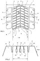
- the figure 1 represents a partial plan view in new condition of a tread pattern of a tread according to a first variant of the invention.
- the tread 1 according to the invention is intended to be part of a tire of size 315 / 70R22.5 intended to equip the drive axle of a heavy vehicle.
- This tread 1 has a running surface 10 in new condition which is shown partially on the figure 1 .
- This strip has a width W measured in the axial direction equal to 270 mm.
- This tread 1 comprises a directional sculpture design imposing a rolling direction.
- This sculpture design comprises two main grooves 2 of circumferential general orientation and having a slightly zigzag geometry around the circumferential direction; these main grooves 2 open on the running surface 10 in the new state and are formed on either side of the equatorial median plane indicated by its trace XX 'in this figure.
- These two main grooves 2 delimit between them a median region M whose width Lm taken between the axially innermost walls of the main grooves 2 is here equal to 159 mm (59% of the total width W).
- These main grooves 2 have an average width equal to 9 mm on the running surface in new condition and a width of 4 mm at a maximum depth equal to 13.5 mm.
- each main groove 2 is formed an edge region B provided with a plurality of oblique grooves 3.
- These oblique grooves 3 delimit a plurality of blocks 31 devoid of any incisions.
- the central region M further comprises three incisions 41, 42, 43 of circumferential orientation opening on the running surface in the new state, each of these incisions being extended in the thickness of the strip by channels 51, 52, 53 respectively, these channels being intended to form new grooves after partial wear. These channels are visible on the figure 2 showing a section of the tread.
- the rate of total hollow volume in the new state is equal to 9.6% while the rate of hollow volume of the middle region in the new state is equal to 3.0%.
- the total void ratio is calculated in the new state of the band by summing the volumes of the circumferential grooves and transverse grooves as well as the volumes of the channels.
- the middle region is provided with a plurality of oblique incisions 6 forming a general V-shaped pattern between the two circumferential grooves.
- These incisions obliques are arranged with a mean pitch Pm equal to 25.1mm.
- These oblique incisions 6 have an average width equal to 0.6 mm and open in the main grooves 2 and in the circumferential incisions 6 of the central region M.
- these oblique incisions 6 open in the channels 51, 52, 53 formed in the thickness of the tread.
- the figure 2 represents a sectional view along a plane perpendicular to the plane of the figure 1 and whose trace on this figure 1 is represented by line II-II.
- the median channel 52 forms a new groove after partial wear equal to 48% while the other new grooves are formed by the other channels 51, 53 after partial wear equal to 56%. These percentages of wear are evaluated with respect to the thickness PMU of material to be used.
- the central channel 52 has an average width of 4.5 mm and a total height of 7 mm.
- the other two channels 51, 53 have a width of 4.5 mm and a height of 6 mm.
- the innermost points of these channels 51, 52, 53 are at the same depth in the tread as the innermost points of the main grooves 2.
- a tread 1 according to the invention for a heavyweight tire of size 11R22.5 comprises two circumferential main grooves 2 dividing the band in its width into a median region M of width Lm equal to 121 mm (54% of the total width W of the strip) and edge regions B of width equal to 42 mm.
- These main grooves 2 have an average width equal to 13 mm and a depth equal to 15.5 mm.
- the clearance angle of the walls of the grooves is equal to 16 degrees with a direction perpendicular to the running surface 10.
- the median region M further comprises two rectilinear incisions 6 of circumferential orientation opening on the running surface 10 in new condition, each of these incisions being extended in the thickness of the strip by channels intended to form new grooves after 51% wear (this percentage is measured with respect to the thickness PMU of material to be used).
- Each channel has an average width equal to 5 mm and a height equal to 8 mm.
- the median region M is provided with a plurality of oblique incisions 6 in a general zigzag pattern between the two main grooves 2. These oblique incisions 6 open in the main grooves and intersect the circumferential incisions 41, 42 These oblique incisions 6 are arranged with a mean pitch Pm equal to 28.7 mm. Each oblique incision 6 extends in the thickness of the strip to a channel 51, 52, these channels being intended to form new grooves after a predetermined partial wear.
- the total hollow volume rate is equal to 9.37% while the hollow volume ratio of the middle region is equal to 2.77%.
- the total hollow volume rate is calculated in the new state of the band by summing the volumes of the main circumferential grooves 2 and the volumes of the channels 51, 52 as well as those of the radial wells 7 and the incisions 41, 42, 6.
- each main groove 2 is formed an edge region B devoid of any groove and incision.
- the figure 4 shows a section along a plane perpendicular to the plane of the figure 3 , this plane passing through line IV-IV visible on the figure 3 . It can be seen that in the middle part are molded two channels 51, 52, these channels being intended to form new grooves when the strip is partially worn in order to ensure the durability of the water discharge performance possibly present on the roadway.
Landscapes
- Engineering & Computer Science (AREA)
- Mechanical Engineering (AREA)
- Tires In General (AREA)
Description
- La présente invention concerne une bande de roulement de pneu pour véhicule poids lourd et plus particulièrement la sculpture d'une telle bande pour un pneu destiné à être monté sur un essieu moteur.
- Pour assurer à la fois une adhérence satisfaisante et un bon drainage de l'eau lors de roulage sur chaussée revêtue d'eau il est nécessaire de former sur une bande de roulement un système de découpures plus ou moins complexe comprenant une pluralité de rainures et d'incisions. Ces découpures forment un dessin de sculpture à la fois sur la surface dite surface de roulement destinée à venir en contact avec la chaussée et dans l'épaisseur de la bande.
- Il est connu notamment par le document de brevet
FR 1452048 - Il est également connu par la publication
WO2010/072523-A1 de former un volume de creux réduit à l'état neuf, ce volume de creux comprenant des parties destinées à former de nouvelles rainures après une usure partielle, ces volumes de creux étant reliés aux rainures formées dès l'état neuf par une pluralité d'incisions transversales. - Le document
WO2013/150143A1 décrit un pneu pour engin hors la route comprenant une bande de roulement dont le taux de creux volumique global à l'état neuf est au plus égal à 15% et dont une région médiane délimitée par des rainures circonférentielles présente un taux de creux inférieur à 10%. - Le document
WO-A-2013/014253 décrit un pneu pour engin hors la route comprenant une bande de roulement ayant deux rainures principales délimitant une région centrale et dont taux global de creux volumique est au plus égal à 15% et dont le taux de creux volumique d'une partie centrale est inférieur au taux de creux volumique de chaque partie de bord. Le problème auquel ce document s'attaque concerne des conditions de roulage sous des charges supérieures à 20 tonnes par pneu, ces conditions pouvant entrainer des séparations entre les couches des armatures. - le document
WO2012/130735 décrit un pneu pour poids lourd comprenant au moins une rainure ondulante dans l'épaisseur de sa bande de roulement, cette rainure comprenant des parties sous la surface de roulement à neuf et des parties ouvertes sur la surface de roulement à neuf. - Le besoin s'est fait sentir d'améliorer encore l'équilibre entre volume total de creux à l'état neuf et les longueurs d'arêtes actives dans le contact de la bande avec la chaussée et cela à différents niveaux d'usure.
- Par direction radiale, on entend dans le présent document une direction qui est perpendiculaire à l'axe de rotation du pneu (cette direction correspond à la direction de l'épaisseur de la bande de roulement).
- Par direction transversale ou axiale, on entend une direction parallèle à l'axe de rotation du pneu.
- Par direction circonférentielle, on entend une direction qui est tangente à tout cercle centré sur l'axe de rotation. Cette direction est perpendiculaire à la fois à la direction axiale et à une direction radiale.
- Plan médian équatorial : c'est un plan perpendiculaire à l'axe de rotation et passant par les points du pneu radialement les plus éloignés dudit axe. Pour une bande de roulement ce plan divise la bande dans sa largeur en deux moitiés d'égales largeurs.
- Une nervure est un élément en relief formé sur une bande de roulement, cet élément s'étendant dans la direction circonférentielle et faisant le tour du pneu. Une nervure comprend deux parois latérales et une face de contact, cette dernière étant destinée à venir en contact avec la chaussée pendant le roulage.
- Une découpure désigne de manière générique soit une rainure soit une incision et correspond à l'espace délimité par des parois de matière se faisant face et distantes l'une de l'autre d'une distance non nulle (dite "largeur de la découpure"). Ce qui différencie une incision d'une rainure c'est précisément cette distance ; dans le cas d'une incision, cette distance est appropriée pour permettre la mise en contact au moins partielle des parois opposées délimitant ladite incision au moins lors du passage dans le contact avec la chaussée. Dans le cas d'une rainure, les parois de cette rainure ne peuvent venir en contact l'une contre l'autre dans les conditions usuelles de roulage.
- Une bande de roulement a une épaisseur maximale PMU de matière à user en roulage ; une fois cette épaisseur atteinte soit le pneu peut être recreusé pour bénéficier de nouvelles rainures soit le pneu est remplacé par un autre pneu neuf.
- Le taux de creux surfacique d'une sculpture est égal au rapport entre la surface des creux formés par les rainures et la surface totale (surface de contact des éléments de relief et surface des creux). Un taux de creux faible indique une grande surface de contact des éléments de relief et une faible surface de creux entre ces éléments.
- Le taux de creux volumique d'une sculpture d'une bande de roulement à l'état neuf est égal au rapport entre le volume des creux (formés notamment par des rainures, des incisions, des cavités) formés dans la bande de roulement et le volume total de ladite bande comprenant le volume de matière à user et le volume des creux. Un taux de creux volumique faible indique un faible volume de creux relativement au volume de matière à user de la bande de roulement.
- Au fur et à mesure de l'usure de la bande de roulement, il est possible de définir un volume de creux restant ainsi qu'un taux de creux volumique.
- Les conditions usuelles de roulage du pneu ou conditions d'utilisation sont celles qui sont définies notamment par la norme E.T.R.T.O. ou toute norme équivalente selon le pays concerné ; ces conditions d'utilisation précisent la pression de gonflage de référence correspondant à la capacité de charge du pneu indiquée par son indice de charge et son code vitesse. Ces conditions d'utilisation peuvent aussi être dites "conditions nominales" ou "conditions d'usage".
- L'empreinte de contact avec la chaussée est réalisée avec le pneu en statique à des conditions qui peuvent être les conditions nominales ou toute autre condition déterminée; à partir de cette empreinte on peut aisément calculer une valeur moyenne de longueur d'empreinte dans la direction circonférentielle.
- La présente invention vise à proposer une bande de roulement pour pneu de véhicule poids lourd, cette bande ayant un dessin de sculpture permettant à la fois une amélioration de la performance en usure ainsi qu'une réduction de résistance au roulement tout en conservant une adhérence appropriée cela quel que soit l'état d'usure de cette bande.
- À cet effet, l'invention a pour objet une bande de roulement pour pneu de véhicule poids lourd, telle que définie dans la revendication 1. Selon l'invention, cette bande de roulement a une largeur totale W et est pourvue de deux rainures d'orientation générale circonférentielle, ces rainures divisant la bande de roulement en trois régions, une région médiane et deux régions de bord axialement de part et d'autre de la région médiane, la région médiane ayant une largeur axiale Lm au moins égale à 45% et au plus 70% de la largeur totale W de la bande de roulement.
- Cette bande a un volume de creux total à l'état neuf V0 ; la partie médiane de cette bande de roulement a un volume de creux total Vm à l'état neuf.
- De plus, cette bande de roulement est telle que la partie médiane comprend une pluralité d'incisions transversales ou obliques ayant une profondeur au moins égale à 75% de la profondeur des rainures principales d'orientation circonférentielle, ces incisions s'ouvrant dans les rainures circonférentielles délimitant la région médiane et étant formées avec un pas moyen Pm.
- Selon l'invention, le taux de creux volumique de la bande à l'état neuf est inférieur à 17% et le taux de creux volumique à l'état neuf de la région médiane est inférieur à la moitié du taux de creux volumique total de la bande à l'état neuf. Le taux de creux volumique total de la bande à l'état neuf étant calculé comme le rapport entre le volume de creux total et un volume total de bande incluant à la fois le volume de matière et le volume de tous les creux, ce volume total de bande étant évalué entre la surface de roulement à l'état neuf et une surface interne s'étendant dans la bande de roulement parallèlement à la surface de roulement à l'état neuf, cette surface interne étant en contact radialement à l'intérieur avec les points les plus à l'intérieur de la bande des rainures circonférentielles les plus profondes.
En outre, cette bande comprend dans sa partie médiane au moins un canal continu circonférentiel qui est formé sous la surface de roulement à l'état neuf pour apparaître après une usure partielle de la bande de roulement et former une nouvelle rainure. Pour faciliter la fabrication, ce au moins un canal est prolongé vers la surface de roulement à l'état neuf par une incision d'orientation principale circonférentielle. - En outre, cette bande comprend dans sa partie médiane au moins deux incisions circonférentielles, ces incisions circonférentielles étant prolongées à l'intérieur de la bande par des parties élargies formant des canaux, ces canaux étant destinés à former de nouvelles rainures après une usure partielle prédéterminée de la bande de roulement.
- Préférentiellement, le nombre d'incisions transversales ou obliques de la région médiane au tour complet de pneu est plus grand que le nombre d'incisions transversales ou obliques de chaque autre région intermédiaire ou de bord.
- Préférentiellement, les régions de bord sont dépourvues d'incisions et de rainures pour former une nervure continue circonférentiellement, soit éventuellement pourvues d'incisions d'orientation transversale (de direction axiale ou oblique) disposées avec un pas moyen Ps, ce pas moyen Ps étant supérieur au pas moyen Pm des incisions formées dans la région médiane.
- Préférentiellement le pas moyen Ps des incisions d'orientation transversale ou oblique dans la région des bords est au moins supérieur à 1.25 fois le pas moyen Pm des incisions de la région médiane.
- La largeur axiale de la région médiane est définie comme la distance axiale moyenne séparant les parois axialement les plus à l'intérieur des rainures circonférentielles délimitant cette région médiane. Cette région médiane est dépourvue de toute rainure circonférentielle s'ouvrant sur la surface de roulement à l'état neuf.
- Par orientation oblique, on entend ici que chaque incision de la partie médiane fait un angle au moins égal à 45 degrés avec la direction circonférentielle.
- Avantageusement, au moins un de ces canaux apparaît au plus tard à partir d'une usure partielle égale à 60% de la profondeur des rainures principales.
- Avantageusement, le taux de creux volumique de la bande à l'état neuf est inférieur à 10% et le taux de creux volumique de la région médiane à l'état neuf est au plus égal à 3%.
- L'invention concerne également un pneu pourvu d'une bande de roulement telle que précédemment définie, ce pneu étant plus particulièrement mais pas uniquement destiné à équiper un essieu moteur d'un véhicule poids lourd.
- D'autres caractéristiques et avantages de l'invention ressortent de la description faite ci-après en référence aux dessins annexés qui montrent, à titre d'exemples non limitatifs, des formes de réalisation de l'objet de l'invention.
-
- La
figure 1 représente une vue en plan d'un dessin de sculpture d'une bande de roulement selon une variante de l'invention ; - La
figure 2 représente une vue en coupe selon un plan perpendiculaire au plan de lafigure 1 et passant par la ligne II-II ; - La
figure 3 représente une vue en plan d'un dessin de sculpture d'une bande de roulement selon une autre variante de l'invention ; - La
figure 4 montre une coupe selon un plan perpendiculaire au plan de lafigure 3 et passant par la ligne IV-IV. - Pour faciliter la lecture des figures, des mêmes signes de référence sont employés pour la description de variantes de l'invention dès lors que ces signes de référence renvoient à des éléments d'une même nature qu'elle soit structurelle ou bien fonctionnelle.
- La
figure 1 représente une vue partielle en plan à l'état neuf d'un dessin de sculpture d'une bande de roulement selon une première variante de l'invention. - La bande de roulement 1 selon l'invention est destinée à faire partie d'un pneu de dimension 315/70R22.5 destiné à équiper l'essieu moteur d'un véhicule poids lourd. Cette bande de roulement 1 a une surface de roulement 10 à l'état neuf qui est montrée partiellement sur la
figure 1 . Cette bande a une largeur W mesurée dans la direction axiale égale à 270 mm. - Cette bande de roulement 1 comprend un dessin de sculpture directionnel imposant une direction de roulage. Ce dessin de sculpture comprend deux rainures principales 2 d'orientation générale circonférentielle et présentant une géométrie en léger zigzag autour de la direction circonférentielle ; ces rainures principales 2 s'ouvrent sur la surface de roulement 10 à l'état neuf et sont formées de part et d'autre du plan médian équatorial indiqué par sa trace XX' sur cette figure. Ces deux rainures principales 2 délimitent entre elles une région médiane M dont la largeur Lm prise entre les parois axialement les plus à l'intérieur des rainures principales 2 est ici égale à 159 mm (soit 59% de la largeur totale W). Ces rainures principales 2 ont une largeur moyenne égale à 9 mm sur la surface de roulement à l'état neuf et une largeur de 4 mm à une profondeur maximale égale à 13.5mm.
- Axialement à l'extérieur de chaque rainure principale 2 est formée une région de bord B pourvue d'une pluralité de rainures obliques 3. Ces rainures obliques 3 délimitent une pluralité de blocs 31 dépourvus de toutes incisions.
- La région médiane M comprend en outre trois incisions 41, 42, 43 d'orientation circonférentielle s'ouvrant sur la surface de roulement à l'état neuf, chacune de ces incisions étant prolongée dans l'épaisseur de la bande par des canaux 51, 52, 53 respectivement, ces canaux étant destinés à former de nouvelles rainures après usure partielle. Ces canaux sont visibles sur la
figure 2 montrant une coupe de la bande de roulement. - Dans le cas de cette première variante, le taux de creux volumique total à l'état neuf est égal à 9.6% alors que le taux de creux volumique de la région médiane à l'état neuf est égal à 3.0%. Le taux de creux volumique total est calculé à l'état neuf de la bande en sommant les volumes des rainures circonférentielles et des rainures transversales ainsi que les volumes des canaux.
- En outre, la région médiane est pourvue d'une pluralité d'incisions obliques 6 formant un motif général en V entre les deux rainures circonférentielles. Ces incisions obliques sont disposées avec un pas moyen Pm égal à 25.1mm. Ces incisions obliques 6 ont une largeur moyenne égale à 0.6 mm et s'ouvrent dans les rainures principales 2 et dans les incisions circonférentielles 6 de la région médiane M. En outre, ces incisions obliques 6 s'ouvrent dans les canaux 51, 52, 53 formés dans l'épaisseur de la bande de roulement.
- La
figure 2 représente une vue en coupe selon un plan perpendiculaire au plan de lafigure 1 et dont la trace sur cettefigure 1 est représentée par la ligne II-II. - Sur cette
figure 2 on constate que le canal médian 52 forme une nouvelle rainure après une usure partielle égale à 48% tandis que les autres nouvelles rainures sont formées par les autres canaux 51, 53 après une usure partielle égale à 56%. Ces pourcentages d'usure sont évalués par rapport à l'épaisseur PMU de matière à user. Le canal central 52 a une largeur moyenne de 4.5 mm et une hauteur totale de 7 mm. Les deux autres canaux 51, 53 ont une largeur de 4.5 mm et une hauteur de 6 mm. Les points les plus à l'intérieur de ces canaux 51, 52, 53 sont à la même profondeur dans la bande de roulement que les points les plus à l'intérieur des rainures principales 2. - Dans une autre variante montrée avec la
figure 3 et avec lafigure 4 , une bande de roulement 1 selon l'invention pour un pneu poids lourd de dimension 11R22.5 comprend deux rainures principales circonférentielles 2 divisant la bande dans sa largeur en une région médiane M de largeur Lm égale à 121 mm (soit 54% de la largeur totale W de la bande) et des régions de bord B de largeur égale à 42 mm. Ces rainures principales 2 ont une largeur moyenne égale à 13 mm et une profondeur égale à 15.5 mm. L'angle de dépouille des parois des rainures est égal à 16 degrés avec une direction perpendiculaire à la surface de roulement 10. - La région médiane M comprend en outre deux incisions rectilignes 6 d'orientation circonférentielle s'ouvrant sur la surface de roulement 10 à l'état neuf, chacune de ces incisions étant prolongée dans l'épaisseur de la bande par des canaux destinés à former de nouvelles rainures après 51% d'usure (ce pourcentage est mesuré par rapport à l'épaisseur PMU de matière à user). Chaque canal a une largeur moyenne égale à 5 mm et une hauteur égale à 8 mm.
- En outre, la région médiane M est pourvue d'une pluralité d'incisions obliques 6 selon un motif général en zigzag entre les deux rainures principales 2. Ces incisions obliques 6 s'ouvrent dans les rainures principales et coupent les incisions circonférentielles 41, 42. Ces incisions obliques 6 sont disposées avec un pas moyen Pm égal à 28.7 mm. Chaque incision oblique 6 s'étend dans l'épaisseur de la bande jusqu'à un canal 51, 52, ces canaux étant destinés à former de nouvelles rainures après une usure partielle prédéterminée.
- À chaque intersection entre une incision oblique 6 et une incision circonférentielle 41, 42 il est formé un puits 7 de direction radiale, lui-même relié à un canal sous-jacent (diamètre du puits égal à 5 mm).
- Dans le cas de cette deuxième variante, le taux de creux volumique total est égal à 9.37% tandis que le taux de creux volumique de la région médiane est égal à 2.77%. Le taux de creux volumique total est calculé à l'état neuf de la bande en sommant les volumes des rainures principales circonférentielles 2 et les volumes des canaux 51, 52 ainsi que ceux des puits radiaux 7 et des incisions 41, 42, 6.
- Axialement à l'extérieur de chaque rainure principale 2 est formée une région de bord B dépourvue de toute rainure et incision.
- La
figure 4 montre une coupe selon un plan perpendiculaire au plan de lafigure 3 , ce plan passant par la ligne IV-IV visible sur lafigure 3 . On voit que dans la partie médiane sont moulés deux canaux 51, 52, ces canaux étant destinés à former de nouvelles rainures lorsque la bande est usée partiellement afin d'assurer une pérennité des performances d'évacuation d'eau éventuellement présente sur la chaussée. - Bien entendu, l'invention n'est pas limitée aux exemples décrits et représentés et diverses modifications peuvent y être apportées sans sortir du cadre défini par les revendications.
Claims (7)
- Bande de roulement (1) pour pneu de véhicule poids lourd, cette bande de roulement ayant une largeur totale W et étant pourvue de deux rainures principales (2) d'orientation générale circonférentielle, ces rainures principales (2) divisant la bande de roulement (1) en trois régions, une région médiane (M) et deux régions de bord (B) axialement de part et d'autre de la région médiane, la région médiane (M) ayant une largeur axiale Lm au moins égale à 45% et au plus 70% de la largeur totale W de la bande de roulement, cette bande ayant un volume de creux total à l'état neuf V0, la partie médiane de cette bande de roulement ayant un volume de creux total Vm à l'état neuf, le taux de creux volumique de la bande à l'état neuf est inférieur à 17%, ce taux de creux étant calculé comme le rapport entre le volume de creux total V0 et un volume total incluant tous les creux et évalué entre la surface de roulement à l'état neuf et une surface interne s'étendant dans la bande de roulement parallèlement à la surface de roulement à l'état neuf, cette surface interne étant en contact radialement à l'intérieur avec les points les plus à l'intérieur des rainures principales (2) les plus profondes, la partie médiane comprenant une pluralité d'incisions (6) transversales ou obliques ayant une profondeur au moins égale à 75% de la profondeur des rainures principales (2), ces incisions (6) transversales ou obliques s'ouvrant dans les rainures principales (2) délimitant la région médiane (M) et étant formées avec un pas moyen Pm, cette bande de roulement (1) étant telle que la région médiane a un taux de creux volumique à l'état neuf inférieur à la moitié du taux de creux volumique total de la bande à l'état neuf, cette bande de roulement étant caractérisée en ce qu'au moins un canal continu circonférentiel est formé sous la surface de roulement à l'état neuf pour apparaître après une usure partielle de la bande de roulement et former une nouvelle rainure et en ce que la bande de roulement comprend en outre dans sa région médiane (M) au moins deux incisions circonférentielles (41, 42, 43), ces incisions circonférentielles étant prolongées à l'intérieur de la bande par des parties élargies formant des canaux (51, 52, 53), ces canaux étant destinés à former de nouvelles rainures après une usure partielle prédéterminée de la bande de roulement.
- Bande de roulement selon la revendication 1 caractérisée en ce que les régions de bord (B) sont des nervures continues circonférentiellement et dépourvues d'incisions et de rainures.
- Bande de roulement selon la revendication 1 caractérisée en ce que les régions de bord (B) sont pourvues d'incisions d'orientation transversale ou oblique (70) disposées avec un pas moyen Ps, ce pas moyen Ps étant supérieur au pas moyen Pm des incisions (40) de la région médiane (M).
- Bande de roulement selon la revendication 3 caractérisée en ce que les régions de bord (B) sont pourvues d'incisions d'orientation transversale ou oblique (70) disposées avec un pas moyen Ps, le pas moyen Ps étant au moins supérieur à 1.25 fois le pas moyen Pm des incisions (40) de la région médiane (M).
- Bande de roulement selon l'une quelconque des revendications 1 à 4 caractérisée en ce qu'au moins un canal (51, 52, 53) formé dans la région médiane apparaît au plus tard à partir d'une usure partielle égale à 60% de la profondeur des rainures principales (2).
- Bande de roulement selon l'une quelconque des revendications 1 à 5 caractérisée en ce que le taux de creux volumique de la bande à l'état neuf est inférieur à 10% et en ce que le taux de creux volumique de la région médiane (M) à l'état neuf est au plus égal à 3%.
- Pneu pourvu d'une bande de roulement selon l'une quelconque des revendications 1 à 6, ce pneu étant plus particulièrement destiné à équiper un essieu moteur d'un véhicule poids lourd.
Applications Claiming Priority (2)
| Application Number | Priority Date | Filing Date | Title |
|---|---|---|---|
| FR1400295A FR3017075B1 (fr) | 2014-02-03 | 2014-02-03 | Bande de roulement pour pneu poids lourd |
| PCT/EP2015/052037 WO2015114128A1 (fr) | 2014-02-03 | 2015-02-02 | Bande de roulement pour pneu poids lourd |
Publications (2)
| Publication Number | Publication Date |
|---|---|
| EP3102437A1 EP3102437A1 (fr) | 2016-12-14 |
| EP3102437B1 true EP3102437B1 (fr) | 2018-12-12 |
Family
ID=50729587
Family Applications (1)
| Application Number | Title | Priority Date | Filing Date |
|---|---|---|---|
| EP15703760.7A Active EP3102437B1 (fr) | 2014-02-03 | 2015-02-02 | Bande de roulement pour pneu poids lourd |
Country Status (5)
| Country | Link |
|---|---|
| US (1) | US10369846B2 (fr) |
| EP (1) | EP3102437B1 (fr) |
| CN (1) | CN105960338B (fr) |
| FR (1) | FR3017075B1 (fr) |
| WO (1) | WO2015114128A1 (fr) |
Families Citing this family (44)
| Publication number | Priority date | Publication date | Assignee | Title |
|---|---|---|---|---|
| WO2017039679A1 (fr) * | 2015-09-04 | 2017-03-09 | Compagnie Generale Des Etablissements Michelin | Bande de roulement de pneu de camion et pneu de camion |
| JP6621312B2 (ja) | 2015-11-24 | 2019-12-18 | 株式会社ブリヂストン | 空気入りタイヤ |
| FR3045465B1 (fr) * | 2015-12-16 | 2017-12-22 | Michelin & Cie | Pneumatique presentant des proprietes d'usure ameliorees |
| FR3045473B1 (fr) * | 2015-12-16 | 2017-12-22 | Michelin & Cie | Pneumatique presentant des proprietes d'usure et de resistance au roulement ameliorees |
| FR3045481B1 (fr) * | 2015-12-16 | 2017-12-22 | Michelin & Cie | Pneumatique presentant des proprietes d'usure et de resistance au roulement ameliorees |
| FR3045483B1 (fr) * | 2015-12-16 | 2017-12-22 | Michelin & Cie | Pneumatique presentant des proprietes d'usure et de resistance au roulement ameliorees |
| FR3045486B1 (fr) * | 2015-12-16 | 2017-12-22 | Michelin & Cie | Pneumatique presentant des proprietes d'usure ameliorees |
| FR3045469B1 (fr) * | 2015-12-16 | 2017-12-22 | Michelin & Cie | Pneumatique presentant des proprietes d'usure et de resistance au roulement ameliorees |
| FR3045487B1 (fr) * | 2015-12-16 | 2017-12-22 | Michelin & Cie | Pneumatique presentant des proprietes d'usure ameliorees |
| US11097531B2 (en) * | 2015-12-17 | 2021-08-24 | Bridgestone Americas Tire Operations, Llc | Additive manufacturing cartridges and processes for producing cured polymeric products by additive manufacturing |
| CN108778780B (zh) | 2016-02-09 | 2020-09-22 | 倍耐力轮胎股份公司 | 用于车辆车轮的轮胎 |
| FR3049218A1 (fr) * | 2016-03-25 | 2017-09-29 | Michelin & Cie | Bande de roulement incisee pour pneu hors la route |
| WO2017176280A1 (fr) * | 2016-04-08 | 2017-10-12 | Compagnie Generale Des Etablissements Michelin | Bande de roulement de pneu de camion et pneu de camion |
| JP6938870B2 (ja) * | 2016-08-29 | 2021-09-22 | 横浜ゴム株式会社 | 空気入りタイヤ |
| FR3061082A1 (fr) * | 2016-12-28 | 2018-06-29 | Compagnie Generale Des Etablissements Michelin | Bande de roulement comportant des cavites cachees |
| FR3061081A1 (fr) * | 2016-12-28 | 2018-06-29 | Compagnie Generale Des Etablissements Michelin | Bande de roulement comportant des cavites cachees |
| JP6838421B2 (ja) * | 2017-02-16 | 2021-03-03 | 住友ゴム工業株式会社 | タイヤ |
| FR3063454A1 (fr) * | 2017-03-03 | 2018-09-07 | Compagnie Generale Des Etablissements Michelin | Bande de roulement de pneu pour vehicule remorque poids lourd |
| JP7092467B2 (ja) * | 2017-06-16 | 2022-06-28 | 株式会社ブリヂストン | タイヤ |
| JP7076444B2 (ja) * | 2017-06-19 | 2022-05-27 | 株式会社ブリヂストン | タイヤ |
| IT201700084726A1 (it) * | 2017-07-25 | 2019-01-25 | Prometeon Tyre Group S R L | Pneumatico per ruote di veicoli |
| US11701925B2 (en) | 2017-12-01 | 2023-07-18 | The Goodyear Tire & Rubber Company | Stabilizer structure for a tread of a tire |
| US11548322B2 (en) * | 2017-12-22 | 2023-01-10 | Compagnie Generale Des Etablissements Michelin | Heavy goods vehicle tire with improved endurance |
| JP7035550B2 (ja) * | 2018-01-18 | 2022-03-15 | 横浜ゴム株式会社 | 空気入りタイヤ |
| EP3802154B1 (fr) * | 2018-05-30 | 2022-04-06 | Compagnie Generale Des Etablissements Michelin | Bande de roulement de pneu comprenant des rainures ondulantes et des incisions |
| CN112739553B (zh) * | 2018-11-09 | 2023-02-28 | 米其林集团总公司 | 具有水流导向胎面特征的卡车轮胎 |
| JP7280155B2 (ja) | 2019-09-19 | 2023-05-23 | 株式会社ブリヂストン | 空気入りタイヤ |
| DE102020201730A1 (de) | 2020-02-12 | 2021-08-12 | Continental Reifen Deutschland Gmbh | Fahrzeugluftreifen |
| DE102020204226A1 (de) | 2020-04-01 | 2021-10-07 | Continental Reifen Deutschland Gmbh | Fahrzeugluftreifen, insbesondere Nutzfahrzeugreifen |
| WO2021261010A1 (fr) * | 2020-06-24 | 2021-12-30 | 住友ゴム工業株式会社 | Pneu |
| CN115916557B (zh) * | 2020-06-24 | 2024-05-31 | 住友橡胶工业株式会社 | 轮胎 |
| FR3112509B1 (fr) * | 2020-07-16 | 2025-04-18 | Michelin & Cie | Pneumatique pour véhicule agricole comprenant une bande de roulement améliorée |
| JP7575662B2 (ja) * | 2020-09-30 | 2024-10-30 | 横浜ゴム株式会社 | タイヤ |
| JP2022057910A (ja) * | 2020-09-30 | 2022-04-11 | 横浜ゴム株式会社 | タイヤ |
| JP7594172B2 (ja) * | 2020-09-30 | 2024-12-04 | 横浜ゴム株式会社 | タイヤ |
| JP7549201B2 (ja) * | 2020-09-30 | 2024-09-11 | 横浜ゴム株式会社 | タイヤ |
| JP7590582B2 (ja) * | 2020-12-18 | 2024-11-26 | ブリヂストン ヨーロッパ エヌブイ/エスエイ | 改良された3段構造のサイプを有するタイヤトレッドおよびタイヤ |
| JP7650690B2 (ja) * | 2021-03-19 | 2025-03-25 | Toyo Tire株式会社 | 空気入りタイヤ |
| DE102021205792A1 (de) * | 2021-06-08 | 2022-12-08 | Continental Reifen Deutschland Gmbh | Fahrzeugluftreifen |
| FR3134037B1 (fr) * | 2022-03-30 | 2024-07-12 | Michelin & Cie | Pneumatique pour un véhicule poids lourd à faible bruit de roulement |
| JP2023180553A (ja) * | 2022-06-09 | 2023-12-21 | 住友ゴム工業株式会社 | タイヤ |
| JP2024099389A (ja) * | 2023-01-12 | 2024-07-25 | 住友ゴム工業株式会社 | タイヤ |
| JP2024170101A (ja) * | 2023-05-26 | 2024-12-06 | 住友ゴム工業株式会社 | 重荷重用タイヤ |
| JP2024176737A (ja) * | 2023-06-09 | 2024-12-19 | 住友ゴム工業株式会社 | 重荷重用タイヤ |
Family Cites Families (5)
| Publication number | Priority date | Publication date | Assignee | Title |
|---|---|---|---|---|
| FR2973284B1 (fr) * | 2011-04-01 | 2014-02-21 | Michelin Soc Tech | Bande de roulement amelioree pour pneu de vehicule poids lourd |
| FR2973285B1 (fr) * | 2011-04-01 | 2013-03-29 | Michelin Soc Tech | Bande de roulement comprenant au moins une rainure ondulante et procede d'obtention |
| FR2978377B1 (fr) * | 2011-07-28 | 2014-12-26 | Michelin Soc Tech | Sculpture pour pneus de vehicule de genie civil |
| FR2989031B1 (fr) * | 2012-04-05 | 2014-05-02 | Michelin & Cie | Bande de roulement de pneu pour essieu moteur de poids lourd |
| FR2995253B1 (fr) * | 2012-09-13 | 2015-01-16 | Michelin & Cie | Bande de roulement et pneu pour poids lourd |
-
2014
- 2014-02-03 FR FR1400295A patent/FR3017075B1/fr not_active Expired - Fee Related
-
2015
- 2015-02-02 CN CN201580006997.4A patent/CN105960338B/zh active Active
- 2015-02-02 EP EP15703760.7A patent/EP3102437B1/fr active Active
- 2015-02-02 WO PCT/EP2015/052037 patent/WO2015114128A1/fr not_active Ceased
- 2015-02-02 US US15/115,968 patent/US10369846B2/en active Active
Non-Patent Citations (1)
| Title |
|---|
| None * |
Also Published As
| Publication number | Publication date |
|---|---|
| US20170174008A1 (en) | 2017-06-22 |
| CN105960338A (zh) | 2016-09-21 |
| CN105960338B (zh) | 2019-05-28 |
| FR3017075B1 (fr) | 2016-02-12 |
| US10369846B2 (en) | 2019-08-06 |
| WO2015114128A1 (fr) | 2015-08-06 |
| FR3017075A1 (fr) | 2015-08-07 |
| EP3102437A1 (fr) | 2016-12-14 |
Similar Documents
| Publication | Publication Date | Title |
|---|---|---|
| EP3102437B1 (fr) | Bande de roulement pour pneu poids lourd | |
| EP3102436B1 (fr) | Bande de roulement pour pneu poids lourd | |
| EP2834089B1 (fr) | Bande de roulement de pneu pour essieu moteur de poids lourd | |
| EP2895338B1 (fr) | Bande de roulement et pneu pour poids lourd | |
| EP3237232B1 (fr) | Bande de roulement pour pneu hivernal poids lourd | |
| EP3160773B1 (fr) | Bande de roulement incisée pour pneu génie civil | |
| EP3126158B1 (fr) | Bande de roulement ayant des canaux sur ses bords | |
| EP2661376B1 (fr) | Pneu pour vehicule poids lourd et arrangement de pneus sur essieu moteur et sur essieu directeur | |
| EP3802154B1 (fr) | Bande de roulement de pneu comprenant des rainures ondulantes et des incisions | |
| FR2973285A1 (fr) | Bande de roulement comprenant au moins une rainure ondulante et procede d'obtention | |
| EP2911894B1 (fr) | Bande de roulement évolutive | |
| EP3648991B1 (fr) | Pneu dont la bande de roulement comprend des rainures ondulantes | |
| EP2318219B1 (fr) | Bande de roulement de pneu a sculpture directionnelle | |
| EP2874829A1 (fr) | Bande de roulement pour pneu d'essieu moteur de poids lourd et pneu | |
| FR2983780A1 (fr) | Bande de roulement a chanfreins variables | |
| EP3044014B1 (fr) | Pneu à dessin de sculpture asymétrique évolutif | |
| EP3383674B1 (fr) | Bande de roulement pour pneu hivernal poids lourd | |
| CA2867582A1 (fr) | Bande de roulement de grande epaisseur pour pneu de genie civil | |
| EP3074244B1 (fr) | Bande de roulement de pneu | |
| EP3383673B1 (fr) | Géométrie de blocs d'une bande de roulement pour pneu |
Legal Events
| Date | Code | Title | Description |
|---|---|---|---|
| PUAI | Public reference made under article 153(3) epc to a published international application that has entered the european phase |
Free format text: ORIGINAL CODE: 0009012 |
|
| STAA | Information on the status of an ep patent application or granted ep patent |
Free format text: STATUS: REQUEST FOR EXAMINATION WAS MADE |
|
| 17P | Request for examination filed |
Effective date: 20160905 |
|
| AK | Designated contracting states |
Kind code of ref document: A1 Designated state(s): AL AT BE BG CH CY CZ DE DK EE ES FI FR GB GR HR HU IE IS IT LI LT LU LV MC MK MT NL NO PL PT RO RS SE SI SK SM TR |
|
| AX | Request for extension of the european patent |
Extension state: BA ME |
|
| DAX | Request for extension of the european patent (deleted) | ||
| RAP1 | Party data changed (applicant data changed or rights of an application transferred) |
Owner name: COMPAGNIE GENERALE DES ETABLISSEMENTS MICHELIN |
|
| RAP1 | Party data changed (applicant data changed or rights of an application transferred) |
Owner name: COMPAGNIE GENERALE DES ETABLISSEMENTS MICHELIN |
|
| STAA | Information on the status of an ep patent application or granted ep patent |
Free format text: STATUS: EXAMINATION IS IN PROGRESS |
|
| 17Q | First examination report despatched |
Effective date: 20180126 |
|
| GRAP | Despatch of communication of intention to grant a patent |
Free format text: ORIGINAL CODE: EPIDOSNIGR1 |
|
| STAA | Information on the status of an ep patent application or granted ep patent |
Free format text: STATUS: GRANT OF PATENT IS INTENDED |
|
| INTG | Intention to grant announced |
Effective date: 20180622 |
|
| GRAS | Grant fee paid |
Free format text: ORIGINAL CODE: EPIDOSNIGR3 |
|
| RAP1 | Party data changed (applicant data changed or rights of an application transferred) |
Owner name: COMPAGNIE GENERALE DES ETABLISSEMENTS MICHELIN |
|
| GRAA | (expected) grant |
Free format text: ORIGINAL CODE: 0009210 |
|
| STAA | Information on the status of an ep patent application or granted ep patent |
Free format text: STATUS: THE PATENT HAS BEEN GRANTED |
|
| AK | Designated contracting states |
Kind code of ref document: B1 Designated state(s): AL AT BE BG CH CY CZ DE DK EE ES FI FR GB GR HR HU IE IS IT LI LT LU LV MC MK MT NL NO PL PT RO RS SE SI SK SM TR |
|
| REG | Reference to a national code |
Ref country code: GB Ref legal event code: FG4D Free format text: NOT ENGLISH |
|
| REG | Reference to a national code |
Ref country code: CH Ref legal event code: EP |
|
| REG | Reference to a national code |
Ref country code: AT Ref legal event code: REF Ref document number: 1075443 Country of ref document: AT Kind code of ref document: T Effective date: 20181215 |
|
| REG | Reference to a national code |
Ref country code: DE Ref legal event code: R096 Ref document number: 602015021211 Country of ref document: DE |
|
| REG | Reference to a national code |
Ref country code: IE Ref legal event code: FG4D Free format text: LANGUAGE OF EP DOCUMENT: FRENCH |
|
| REG | Reference to a national code |
Ref country code: NL Ref legal event code: MP Effective date: 20181212 |
|
| REG | Reference to a national code |
Ref country code: LT Ref legal event code: MG4D |
|
| PG25 | Lapsed in a contracting state [announced via postgrant information from national office to epo] |
Ref country code: FI Free format text: LAPSE BECAUSE OF FAILURE TO SUBMIT A TRANSLATION OF THE DESCRIPTION OR TO PAY THE FEE WITHIN THE PRESCRIBED TIME-LIMIT Effective date: 20181212 Ref country code: LV Free format text: LAPSE BECAUSE OF FAILURE TO SUBMIT A TRANSLATION OF THE DESCRIPTION OR TO PAY THE FEE WITHIN THE PRESCRIBED TIME-LIMIT Effective date: 20181212 Ref country code: NO Free format text: LAPSE BECAUSE OF FAILURE TO SUBMIT A TRANSLATION OF THE DESCRIPTION OR TO PAY THE FEE WITHIN THE PRESCRIBED TIME-LIMIT Effective date: 20190312 Ref country code: BG Free format text: LAPSE BECAUSE OF FAILURE TO SUBMIT A TRANSLATION OF THE DESCRIPTION OR TO PAY THE FEE WITHIN THE PRESCRIBED TIME-LIMIT Effective date: 20190312 Ref country code: LT Free format text: LAPSE BECAUSE OF FAILURE TO SUBMIT A TRANSLATION OF THE DESCRIPTION OR TO PAY THE FEE WITHIN THE PRESCRIBED TIME-LIMIT Effective date: 20181212 Ref country code: HR Free format text: LAPSE BECAUSE OF FAILURE TO SUBMIT A TRANSLATION OF THE DESCRIPTION OR TO PAY THE FEE WITHIN THE PRESCRIBED TIME-LIMIT Effective date: 20181212 Ref country code: ES Free format text: LAPSE BECAUSE OF FAILURE TO SUBMIT A TRANSLATION OF THE DESCRIPTION OR TO PAY THE FEE WITHIN THE PRESCRIBED TIME-LIMIT Effective date: 20181212 |
|
| REG | Reference to a national code |
Ref country code: AT Ref legal event code: MK05 Ref document number: 1075443 Country of ref document: AT Kind code of ref document: T Effective date: 20181212 |
|
| PG25 | Lapsed in a contracting state [announced via postgrant information from national office to epo] |
Ref country code: AL Free format text: LAPSE BECAUSE OF FAILURE TO SUBMIT A TRANSLATION OF THE DESCRIPTION OR TO PAY THE FEE WITHIN THE PRESCRIBED TIME-LIMIT Effective date: 20181212 Ref country code: GR Free format text: LAPSE BECAUSE OF FAILURE TO SUBMIT A TRANSLATION OF THE DESCRIPTION OR TO PAY THE FEE WITHIN THE PRESCRIBED TIME-LIMIT Effective date: 20190313 Ref country code: SE Free format text: LAPSE BECAUSE OF FAILURE TO SUBMIT A TRANSLATION OF THE DESCRIPTION OR TO PAY THE FEE WITHIN THE PRESCRIBED TIME-LIMIT Effective date: 20181212 Ref country code: RS Free format text: LAPSE BECAUSE OF FAILURE TO SUBMIT A TRANSLATION OF THE DESCRIPTION OR TO PAY THE FEE WITHIN THE PRESCRIBED TIME-LIMIT Effective date: 20181212 |
|
| PG25 | Lapsed in a contracting state [announced via postgrant information from national office to epo] |
Ref country code: NL Free format text: LAPSE BECAUSE OF FAILURE TO SUBMIT A TRANSLATION OF THE DESCRIPTION OR TO PAY THE FEE WITHIN THE PRESCRIBED TIME-LIMIT Effective date: 20181212 |
|
| PG25 | Lapsed in a contracting state [announced via postgrant information from national office to epo] |
Ref country code: IT Free format text: LAPSE BECAUSE OF FAILURE TO SUBMIT A TRANSLATION OF THE DESCRIPTION OR TO PAY THE FEE WITHIN THE PRESCRIBED TIME-LIMIT Effective date: 20181212 Ref country code: CZ Free format text: LAPSE BECAUSE OF FAILURE TO SUBMIT A TRANSLATION OF THE DESCRIPTION OR TO PAY THE FEE WITHIN THE PRESCRIBED TIME-LIMIT Effective date: 20181212 Ref country code: PT Free format text: LAPSE BECAUSE OF FAILURE TO SUBMIT A TRANSLATION OF THE DESCRIPTION OR TO PAY THE FEE WITHIN THE PRESCRIBED TIME-LIMIT Effective date: 20190412 Ref country code: PL Free format text: LAPSE BECAUSE OF FAILURE TO SUBMIT A TRANSLATION OF THE DESCRIPTION OR TO PAY THE FEE WITHIN THE PRESCRIBED TIME-LIMIT Effective date: 20181212 |
|
| PG25 | Lapsed in a contracting state [announced via postgrant information from national office to epo] |
Ref country code: EE Free format text: LAPSE BECAUSE OF FAILURE TO SUBMIT A TRANSLATION OF THE DESCRIPTION OR TO PAY THE FEE WITHIN THE PRESCRIBED TIME-LIMIT Effective date: 20181212 Ref country code: SM Free format text: LAPSE BECAUSE OF FAILURE TO SUBMIT A TRANSLATION OF THE DESCRIPTION OR TO PAY THE FEE WITHIN THE PRESCRIBED TIME-LIMIT Effective date: 20181212 Ref country code: RO Free format text: LAPSE BECAUSE OF FAILURE TO SUBMIT A TRANSLATION OF THE DESCRIPTION OR TO PAY THE FEE WITHIN THE PRESCRIBED TIME-LIMIT Effective date: 20181212 Ref country code: IS Free format text: LAPSE BECAUSE OF FAILURE TO SUBMIT A TRANSLATION OF THE DESCRIPTION OR TO PAY THE FEE WITHIN THE PRESCRIBED TIME-LIMIT Effective date: 20190412 Ref country code: SK Free format text: LAPSE BECAUSE OF FAILURE TO SUBMIT A TRANSLATION OF THE DESCRIPTION OR TO PAY THE FEE WITHIN THE PRESCRIBED TIME-LIMIT Effective date: 20181212 |
|
| REG | Reference to a national code |
Ref country code: DE Ref legal event code: R097 Ref document number: 602015021211 Country of ref document: DE |
|
| REG | Reference to a national code |
Ref country code: CH Ref legal event code: PL |
|
| PLBE | No opposition filed within time limit |
Free format text: ORIGINAL CODE: 0009261 |
|
| STAA | Information on the status of an ep patent application or granted ep patent |
Free format text: STATUS: NO OPPOSITION FILED WITHIN TIME LIMIT |
|
| PG25 | Lapsed in a contracting state [announced via postgrant information from national office to epo] |
Ref country code: DK Free format text: LAPSE BECAUSE OF FAILURE TO SUBMIT A TRANSLATION OF THE DESCRIPTION OR TO PAY THE FEE WITHIN THE PRESCRIBED TIME-LIMIT Effective date: 20181212 Ref country code: MC Free format text: LAPSE BECAUSE OF FAILURE TO SUBMIT A TRANSLATION OF THE DESCRIPTION OR TO PAY THE FEE WITHIN THE PRESCRIBED TIME-LIMIT Effective date: 20181212 Ref country code: LU Free format text: LAPSE BECAUSE OF NON-PAYMENT OF DUE FEES Effective date: 20190202 Ref country code: SI Free format text: LAPSE BECAUSE OF FAILURE TO SUBMIT A TRANSLATION OF THE DESCRIPTION OR TO PAY THE FEE WITHIN THE PRESCRIBED TIME-LIMIT Effective date: 20181212 Ref country code: AT Free format text: LAPSE BECAUSE OF FAILURE TO SUBMIT A TRANSLATION OF THE DESCRIPTION OR TO PAY THE FEE WITHIN THE PRESCRIBED TIME-LIMIT Effective date: 20181212 |
|
| 26N | No opposition filed |
Effective date: 20190913 |
|
| REG | Reference to a national code |
Ref country code: BE Ref legal event code: MM Effective date: 20190228 |
|
| GBPC | Gb: european patent ceased through non-payment of renewal fee |
Effective date: 20190312 |
|
| REG | Reference to a national code |
Ref country code: IE Ref legal event code: MM4A |
|
| PG25 | Lapsed in a contracting state [announced via postgrant information from national office to epo] |
Ref country code: LI Free format text: LAPSE BECAUSE OF NON-PAYMENT OF DUE FEES Effective date: 20190228 Ref country code: CH Free format text: LAPSE BECAUSE OF NON-PAYMENT OF DUE FEES Effective date: 20190228 |
|
| PG25 | Lapsed in a contracting state [announced via postgrant information from national office to epo] |
Ref country code: GB Free format text: LAPSE BECAUSE OF NON-PAYMENT OF DUE FEES Effective date: 20190312 Ref country code: IE Free format text: LAPSE BECAUSE OF NON-PAYMENT OF DUE FEES Effective date: 20190202 |
|
| PG25 | Lapsed in a contracting state [announced via postgrant information from national office to epo] |
Ref country code: BE Free format text: LAPSE BECAUSE OF NON-PAYMENT OF DUE FEES Effective date: 20190228 |
|
| PG25 | Lapsed in a contracting state [announced via postgrant information from national office to epo] |
Ref country code: TR Free format text: LAPSE BECAUSE OF FAILURE TO SUBMIT A TRANSLATION OF THE DESCRIPTION OR TO PAY THE FEE WITHIN THE PRESCRIBED TIME-LIMIT Effective date: 20181212 |
|
| PG25 | Lapsed in a contracting state [announced via postgrant information from national office to epo] |
Ref country code: MT Free format text: LAPSE BECAUSE OF FAILURE TO SUBMIT A TRANSLATION OF THE DESCRIPTION OR TO PAY THE FEE WITHIN THE PRESCRIBED TIME-LIMIT Effective date: 20181212 |
|
| PG25 | Lapsed in a contracting state [announced via postgrant information from national office to epo] |
Ref country code: CY Free format text: LAPSE BECAUSE OF FAILURE TO SUBMIT A TRANSLATION OF THE DESCRIPTION OR TO PAY THE FEE WITHIN THE PRESCRIBED TIME-LIMIT Effective date: 20181212 |
|
| PG25 | Lapsed in a contracting state [announced via postgrant information from national office to epo] |
Ref country code: HU Free format text: LAPSE BECAUSE OF FAILURE TO SUBMIT A TRANSLATION OF THE DESCRIPTION OR TO PAY THE FEE WITHIN THE PRESCRIBED TIME-LIMIT; INVALID AB INITIO Effective date: 20150202 |
|
| PG25 | Lapsed in a contracting state [announced via postgrant information from national office to epo] |
Ref country code: MK Free format text: LAPSE BECAUSE OF FAILURE TO SUBMIT A TRANSLATION OF THE DESCRIPTION OR TO PAY THE FEE WITHIN THE PRESCRIBED TIME-LIMIT Effective date: 20181212 |
|
| PGFP | Annual fee paid to national office [announced via postgrant information from national office to epo] |
Ref country code: DE Payment date: 20260218 Year of fee payment: 12 |
|
| PGFP | Annual fee paid to national office [announced via postgrant information from national office to epo] |
Ref country code: FR Payment date: 20260218 Year of fee payment: 12 |