EP3102445B1 - Ensemble de suspension pneumatique comprenant une soupape de commande intégrée et un moyen d'actionnement en forme de bascule - Google Patents
Ensemble de suspension pneumatique comprenant une soupape de commande intégrée et un moyen d'actionnement en forme de bascule Download PDFInfo
- Publication number
- EP3102445B1 EP3102445B1 EP15702462.1A EP15702462A EP3102445B1 EP 3102445 B1 EP3102445 B1 EP 3102445B1 EP 15702462 A EP15702462 A EP 15702462A EP 3102445 B1 EP3102445 B1 EP 3102445B1
- Authority
- EP
- European Patent Office
- Prior art keywords
- air spring
- valve
- spring arrangement
- arrangement according
- actuating
- Prior art date
- Legal status (The legal status is an assumption and is not a legal conclusion. Google has not performed a legal analysis and makes no representation as to the accuracy of the status listed.)
- Active
Links
Images

Classifications
-
- B—PERFORMING OPERATIONS; TRANSPORTING
- B60—VEHICLES IN GENERAL
- B60G—VEHICLE SUSPENSION ARRANGEMENTS
- B60G15/00—Resilient suspensions characterised by arrangement, location or type of combined spring and vibration damper, e.g. telescopic type
- B60G15/08—Resilient suspensions characterised by arrangement, location or type of combined spring and vibration damper, e.g. telescopic type having fluid spring
- B60G15/12—Resilient suspensions characterised by arrangement, location or type of combined spring and vibration damper, e.g. telescopic type having fluid spring and fluid damper
-
- B—PERFORMING OPERATIONS; TRANSPORTING
- B60—VEHICLES IN GENERAL
- B60G—VEHICLE SUSPENSION ARRANGEMENTS
- B60G17/00—Resilient suspensions having means for adjusting the spring or vibration-damper characteristics, for regulating the distance between a supporting surface and a sprung part of vehicle or for locking suspension during use to meet varying vehicular or surface conditions, e.g. due to speed or load
- B60G17/02—Spring characteristics, e.g. mechanical springs and mechanical adjusting means
- B60G17/04—Spring characteristics, e.g. mechanical springs and mechanical adjusting means fluid spring characteristics
- B60G17/048—Spring characteristics, e.g. mechanical springs and mechanical adjusting means fluid spring characteristics with the regulating means inside the fluid springs
- B60G17/0485—Spring characteristics, e.g. mechanical springs and mechanical adjusting means fluid spring characteristics with the regulating means inside the fluid springs the springs being pneumatic springs with a flexible wall, e.g. with levelling valves
-
- B—PERFORMING OPERATIONS; TRANSPORTING
- B60—VEHICLES IN GENERAL
- B60G—VEHICLE SUSPENSION ARRANGEMENTS
- B60G17/00—Resilient suspensions having means for adjusting the spring or vibration-damper characteristics, for regulating the distance between a supporting surface and a sprung part of vehicle or for locking suspension during use to meet varying vehicular or surface conditions, e.g. due to speed or load
- B60G17/02—Spring characteristics, e.g. mechanical springs and mechanical adjusting means
- B60G17/04—Spring characteristics, e.g. mechanical springs and mechanical adjusting means fluid spring characteristics
- B60G17/052—Pneumatic spring characteristics
- B60G17/0523—Regulating distributors or valves for pneumatic springs
- B60G17/0525—Height adjusting or levelling valves
-
- B—PERFORMING OPERATIONS; TRANSPORTING
- B60—VEHICLES IN GENERAL
- B60G—VEHICLE SUSPENSION ARRANGEMENTS
- B60G17/00—Resilient suspensions having means for adjusting the spring or vibration-damper characteristics, for regulating the distance between a supporting surface and a sprung part of vehicle or for locking suspension during use to meet varying vehicular or surface conditions, e.g. due to speed or load
- B60G17/02—Spring characteristics, e.g. mechanical springs and mechanical adjusting means
- B60G17/04—Spring characteristics, e.g. mechanical springs and mechanical adjusting means fluid spring characteristics
- B60G17/052—Pneumatic spring characteristics
- B60G17/0523—Regulating distributors or valves for pneumatic springs
- B60G17/0528—Pressure regulating or air filling valves
-
- F—MECHANICAL ENGINEERING; LIGHTING; HEATING; WEAPONS; BLASTING
- F16—ENGINEERING ELEMENTS AND UNITS; GENERAL MEASURES FOR PRODUCING AND MAINTAINING EFFECTIVE FUNCTIONING OF MACHINES OR INSTALLATIONS; THERMAL INSULATION IN GENERAL
- F16F—SPRINGS; SHOCK-ABSORBERS; MEANS FOR DAMPING VIBRATION
- F16F9/00—Springs, vibration-dampers, shock-absorbers, or similarly-constructed movement-dampers using a fluid or the equivalent as damping medium
- F16F9/02—Springs, vibration-dampers, shock-absorbers, or similarly-constructed movement-dampers using a fluid or the equivalent as damping medium using gas only or vacuum
- F16F9/04—Springs, vibration-dampers, shock-absorbers, or similarly-constructed movement-dampers using a fluid or the equivalent as damping medium using gas only or vacuum in a chamber with a flexible wall
- F16F9/05—Springs, vibration-dampers, shock-absorbers, or similarly-constructed movement-dampers using a fluid or the equivalent as damping medium using gas only or vacuum in a chamber with a flexible wall the flexible wall being of the rolling diaphragm type
-
- F—MECHANICAL ENGINEERING; LIGHTING; HEATING; WEAPONS; BLASTING
- F16—ENGINEERING ELEMENTS AND UNITS; GENERAL MEASURES FOR PRODUCING AND MAINTAINING EFFECTIVE FUNCTIONING OF MACHINES OR INSTALLATIONS; THERMAL INSULATION IN GENERAL
- F16F—SPRINGS; SHOCK-ABSORBERS; MEANS FOR DAMPING VIBRATION
- F16F9/00—Springs, vibration-dampers, shock-absorbers, or similarly-constructed movement-dampers using a fluid or the equivalent as damping medium
- F16F9/32—Details
- F16F9/43—Filling or drainage arrangements, e.g. for supply of gas
-
- F—MECHANICAL ENGINEERING; LIGHTING; HEATING; WEAPONS; BLASTING
- F16—ENGINEERING ELEMENTS AND UNITS; GENERAL MEASURES FOR PRODUCING AND MAINTAINING EFFECTIVE FUNCTIONING OF MACHINES OR INSTALLATIONS; THERMAL INSULATION IN GENERAL
- F16F—SPRINGS; SHOCK-ABSORBERS; MEANS FOR DAMPING VIBRATION
- F16F9/00—Springs, vibration-dampers, shock-absorbers, or similarly-constructed movement-dampers using a fluid or the equivalent as damping medium
- F16F9/32—Details
- F16F9/50—Special means providing automatic damping adjustment, i.e. self-adjustment of damping by particular sliding movements of a valve element, other than flexions or displacement of valve discs; Special means providing self-adjustment of spring characteristics
- F16F9/512—Means responsive to load action, i.e. static load on the damper or dynamic fluid pressure changes in the damper, e.g. due to changes in velocity
- F16F9/5123—Means responsive to load action, i.e. static load on the damper or dynamic fluid pressure changes in the damper, e.g. due to changes in velocity responsive to the static or steady-state load on the damper
-
- B—PERFORMING OPERATIONS; TRANSPORTING
- B60—VEHICLES IN GENERAL
- B60G—VEHICLE SUSPENSION ARRANGEMENTS
- B60G2202/00—Indexing codes relating to the type of spring, damper or actuator
- B60G2202/30—Spring/Damper and/or actuator Units
- B60G2202/31—Spring/Damper and/or actuator Units with the spring arranged around the damper, e.g. MacPherson strut
- B60G2202/314—The spring being a pneumatic spring
-
- B—PERFORMING OPERATIONS; TRANSPORTING
- B60—VEHICLES IN GENERAL
- B60G—VEHICLE SUSPENSION ARRANGEMENTS
- B60G2204/00—Indexing codes related to suspensions per se or to auxiliary parts
- B60G2204/10—Mounting of suspension elements
- B60G2204/12—Mounting of springs or dampers
- B60G2204/126—Mounting of pneumatic springs
- B60G2204/1262—Mounting of pneumatic springs on a damper
-
- B—PERFORMING OPERATIONS; TRANSPORTING
- B60—VEHICLES IN GENERAL
- B60G—VEHICLE SUSPENSION ARRANGEMENTS
- B60G2204/00—Indexing codes related to suspensions per se or to auxiliary parts
- B60G2204/40—Auxiliary suspension parts; Adjustment of suspensions
- B60G2204/423—Rails, tubes, or the like, for guiding the movement of suspension elements
- B60G2204/4232—Sliding mounts
-
- B—PERFORMING OPERATIONS; TRANSPORTING
- B60—VEHICLES IN GENERAL
- B60G—VEHICLE SUSPENSION ARRANGEMENTS
- B60G2400/00—Indexing codes relating to detected, measured or calculated conditions or factors
- B60G2400/25—Stroke; Height; Displacement
- B60G2400/252—Stroke; Height; Displacement vertical
-
- B—PERFORMING OPERATIONS; TRANSPORTING
- B60—VEHICLES IN GENERAL
- B60G—VEHICLE SUSPENSION ARRANGEMENTS
- B60G2500/00—Indexing codes relating to the regulated action or device
- B60G2500/20—Spring action or springs
- B60G2500/204—Pressure regulating valves for air-springs
- B60G2500/2042—Air filling valves
-
- B—PERFORMING OPERATIONS; TRANSPORTING
- B60—VEHICLES IN GENERAL
- B60G—VEHICLE SUSPENSION ARRANGEMENTS
- B60G2500/00—Indexing codes relating to the regulated action or device
- B60G2500/20—Spring action or springs
- B60G2500/204—Pressure regulating valves for air-springs
- B60G2500/2044—Air exhausting valves
Definitions
- the invention relates to an air spring assembly having an integrated control valve arrangement for pressurizing a formed between an outer tube, a roll tube and these components connecting air spring bellows spring pressure chamber, wherein the control valve assembly consists of a single vent valve and a single vent valve by integrated mechanical actuation means in accordance with the Beerfederhub ein for loading or bleeding the spring pressure chamber can be actuated.
- the field of application of the invention extends primarily to the vehicle technology.
- vibration dampers which comprise a mostly hydraulic damping element and a hereby cooperating air spring arrangement.
- the damping element usually has a container tube which is connected to a roll tube of the air spring, wherein the roll tube is connected via a bellows acting as a bellows with a concentric and relative to the roll tube axially movably arranged outer tube.
- the bellows, the roll-off tube and the outer tube define a spring pressure chamber that is under spring pressure.
- the suspension of a cab on a chassis of a commercial vehicle is equipped to those of the road on the suspension to keep the vibrations introduced into the chassis largely away from the cab.
- From the DE 10 2010 012 346 A1 is an air spring assembly for a commercial vehicle, in which internally a control valve assembly is provided to supply or remove compressed air with respect to the spring pressure chamber. About also disposed within the spring pressure chamber mechanical actuating means, the control valve arrangement can be controlled depending on the height level. Usually, the spring pressure chamber is supplied with compressed air when the air spring drops to the minimum height level to restore the suspension characteristics. A venting of the spring pressure chamber, however, takes place when the height level of the spring assembly is to be reduced.
- control valve arrangement in this prior art consists of two individual valves for respectively ventilating and venting the spring pressure chamber. Both individual valves are arranged on the part of the roll-off tube and are actuated via a spring-biased mechanical actuating means, which is mounted on the part of the outer tube.
- the spring-biased mechanical actuating means acts against a likewise spring-biased actuating tappet of the two individual valves.
- this technical solution may result in an indefinite switching point for the valve actuation.
- the actuating tappets in this prior art are of different lengths and are actuated in the same direction, there may be undesirable overlaps of switching states.
- the EP 1 327 538 A2 discloses an air spring assembly with also integrated control valve assembly for loading or venting of the spring pressure chamber.
- the actuation of the control valve assembly takes place here via a likewise arranged within the air spring control, which acts on one of the two relatively movable air spring assemblies Abrollrohr or outer tube.
- the control element has an effective length, which is shorter than the stroke length of the air spring and is biased by a spring against one of the mutually movable air spring assemblies.
- the control is floating relative to two air spring assemblies, in which a second spring, the force direction is effective against the aforementioned first spring, the position of the control codetermines. Due to the floating bearing, undefined switching states can also occur over the lifetime. This means that a ventilation or venting of the spring pressure chamber is not reliably triggered as desired at a defined stroke position of the air spring assembly.
- the DE 100 03 054 A1 discloses another air spring assembly with integrated control valve assembly and mechanical actuation means for actuating the control valve assembly.
- the actuating means has a guideway and engages one of the two relatively movable air spring assemblies.
- the control valve assembly is designed as a rotary slide valve, wherein the guide rail of the actuating means is designed to be shorter than the stroke length of the air spring and the actuating means in releasable operative connection with the supporting this air spring assembly.
- the invention includes the technical teaching that the vent valve of the control valve assembly is disposed opposite the vent valve with actuating tappets facing each other, wherein the mechanical actuating means acting thereon comprise a Wegwipphebel mounted with one end in at least one guideway of the Abrollrohr or outer tube Actuator engages to act with the other end on the actuating plunger for switching the control valve assembly.
- the advantage of the solution according to the invention is, in particular, that due to the springless coupling of the mechanical actuating means to the control valve arrangement, related manufacturing tolerances and fatigue phenomena have no influence on the switching states of the control valve arrangement.
- Over the entire Heilfederhubweg the switching position of the ventilation valve and the vent valve and in particular the relative switching position is always defined to each other, so that in particular can not come to fürströmlexicen during a switching position change.
- the solution of the invention forms by the preferably over the entire Heilfederhubweg extending guideway for the Wennwipphebel a kind of forced operation of the valve actuation, which is achieved with a low technical component cost.
- the actuation tappets of venting valve and venting valve are arranged coaxially with respect to one another in order to integrate the valve arrangement in the region of the rolling-off tube in a space-saving manner.
- both the vent valve and the vent valve are designed as spring-return monostable 2/2-way slide valves.
- a feed pressure port P of the ventilation valve is connected to a working line connection A, which forwards the compressed air to the spring pressure chamber. In the locked position, this connection is interrupted.
- a connection of a working line port A which is in communication with the spring pressure chamber, with a vent port R, which leads to the atmosphere prepared. The blocking position prevents this connection.
- the mechanical actuating means for controlling the thus formed control valve arrangement are designed so that only either the vent valve or the vent valve is actuated, so that overlaps in the switching states can not take place.
- the at least one guide track having actuating element for the Heidelbergwipphebel is mounted on the part of a distal end via a hinge assembly on the outer tube.
- the joint arrangement compensates for non-axial relative movements between the outer tube and the rolling tube, so that jamming of relatively movable components can not occur.
- the actuating element is arranged on the part of the roll-off tube, so that the control valve arrangement is placed on the part of the outer tube.
- the actuating element is sleeve-shaped and has two guide webs arranged opposite one another on the outer lateral surface. This provides the prerequisite for the Wennwipphebel is formed fork-shaped at the end facing the actuating element and engages positively in the opposite guideways. As a result, a precise operating actuating mechanism for the control valve arrangement is achieved.
- the sleeve-shaped actuator can also be integrated space-saving within the air spring assembly.
- the actuating element in the roll-off against rotation about the longitudinal axis of the air suspension arrangement can be performed.
- the guideway comprises an upper web portion associated with the vent valve, which serves to pivot the rocker arm in the region of a low Luftfederhub too in the direction of actuation of the venting valve. During such operation of the vent valve, the vent valve remains unactuated.
- vent valve An actuation of the vent valve occurs when the rocker arm reaches the region of a lower web portion, which is achieved when the air spring assembly is in an upper Luftfederhub too. In this other switching position, the vent valve remains unactuated.
- the air spring arrangement consists essentially of an outer tube 1 with upper mounting lug 2 for attachment to a cab of a commercial vehicle, not shown, and a roll tube 3 with lower mounting lug 4 for attachment to the air spring assembly on a chassis of the commercial vehicle.
- the outer tube 1 is connected to the roll-off tube 3 by an air spring bellows 5, so that a spring-pressure chamber 6 is formed between the outer tube 1, the roll-off tube 3 and the air spring bellows 5.
- the air spring cooperates with an integrated hydraulic shock absorber 7, which serves to dampen the sprung mass.
- the spring pressure chamber 6 of the air spring assembly can be acted upon via an integrated control valve assembly consisting of a single vent valve 8 and a single vent valve 9, depending on the load with compressed air.
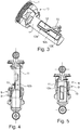
- the vent valve 8 and the vent valve 9 are actuated by also integrated mechanical actuating means comprising a actuated in accordance with the Heilfederhub ein Druckwipphebels 10.
- FIG. 2 engages the Wegwipphebel 10 on the part of the control valve assembly with one end to the opposite and frontally facing each other actuating plunger 8a of the vent valve 8 and actuating plunger 9a of the vent valve 9 at.
- the actuating plunger 8a of the venting valve 8 is arranged coaxially with the actuating plunger 9a of the venting valve 9.
- the vent valve 8 and the vent valve 9 are formed as spring-return monostable 2/2-way slide valves. While the venting valve 8 connects a feed pressure port P to a work line port A for pressurizing the spring pressure chamber (not shown), the spring pressure chamber can be vented with the vent valve 9 by connecting the work line port A to a vent port R.
- vent valve 8 and the vent valve 9 are mutually actuated by the Heidelbergwipphebel 10.
- the activation takes place in such a way that the venting valve (8) and the venting valve (9) are opened or closed by the web sections (12a, 12b), depending on the lifting movement of the spring arrangement, but not in a linearly proportional manner.
- the Wegwipphebel 10 cooperates with a sleeve-shaped actuating element 11.
- the control valve arrangement remote from the end of the rocker lever engages 10 in guideways 12, which extend along the entire Beerfederhubwegs the air spring assembly.
- the two on the sleeve-shaped actuator 11 opposite guide tracks 12 act with a fork-shaped end of the rocker arm 10 positively together.
- the actuator 11 is mounted on the part of a distal end via a ball joint assembly 13 on the outer tube 1 of the air spring assembly.
- the guideway 12 is composed of a plurality of functional sections and has an upper track portion 12a for pivoting the rocker arm 10 in the region of a low Heilfederhub too, a lower track portion 12b for pivoting the rocker arm 10 in the region of an upper Heilfederhub too and an intermediate and both track sections extending transversely middle web section 12 c, which holds the Wegwipphebel 10 at medium Vietnamesefederhub too in the neutral position, as in FIG. 1 shown.
Landscapes
- Engineering & Computer Science (AREA)
- Mechanical Engineering (AREA)
- General Engineering & Computer Science (AREA)
- Physics & Mathematics (AREA)
- Fluid Mechanics (AREA)
- Fluid-Damping Devices (AREA)
- Vehicle Body Suspensions (AREA)
- Multiple-Way Valves (AREA)
Claims (13)
- Agencement de suspension pneumatique, comprenant un agencement intégré de soupape de commande pour l'alimentation en air comprimé d'une chambre (6) de pression de suspension formée entre un tuyau (1) extérieur, un tuyau (3) de déroulement et un coussin (5) d'air reliant ces pièces, l'agencement de soupape de commande étant constitué d'une soupape (8) individuelle d'alimentation en air et d'une soupape (9) individuelle de purge d'air, qui peuvent être actionnées par des moyens d'actionnement mécaniques également intégrés en fonction de la position de course de la suspension pneumatique pour alimenter en air la chambre (6) de pression de suspension ou l'en purger,
caractérisé en ce que la soupape (8) d'alimentation en air est disposée en opposition à la soupape (9) de purge d'air avec des poussoirs (8a; 9a) d'actionnement tournés l'un vers l'autre du côté du tuyau (1) extérieur ou du tuyau (3) de déroulement, les moyens d'actionnement mécaniques, agissant intermédiairement, comprenant un levier (10) de bascule de commutation, qui attaque par l'une des extrémités au moins une voie (12) de guidage d'un élément (11) d'actionnement mis sur le tuyau (3) de déroulement ou le tuyau (1) extérieur et qui agit par l'autre extrémité sur les poussoirs (8a, 8b) d'actionnement pour la commutation de l'agencement de la soupape de commande. - Agencement de suspension pneumatique suivant la revendication 1,
caractérisé en ce que la voie (12) de guidage de l'élément (11) d'actionnement s'étend sur tout le trajet de course de la suspension. - Agencement de suspension pneumatique suivant la revendication 1,
caractérisé en ce que les poussoirs (8a; 9a) d'actionnement de la soupape (8) d'alimentation en air et de la soupape (9) de purge d'air sont disposés coaxialement l'un à l'autre. - Agencement de suspension pneumatique suivant la revendication 1,
caractérisé en ce que la soupape (8) d'alimentation en air et la soupape (9) de purge d'air sont constituées en mode de construction à tiroir ou à soupape à siège sous la forme d'une soupape 2/2 voies monostables rappelée par ressort. - Agencement de suspension pneumatique suivant la revendication 1,
caractérisé en ce que les sections transversales d'écoulement ouvertes de la soupape (8) d'alimentation en air et/ou de la soupape (9) de purge d'air se modifient en fonction du déplacement linéaire du poussoir (8a; 9a) d'actionnement de type à tiroir. - Agencement de suspension pneumatique suivant la revendication 1,
caractérisé en ce que l'élément (11) d'actionnement est mis du côté d'une extrémité distale sur le tuyau (1) extérieur par un agencement (13) d'articulation à bille coaxial à l'axe longitudinal de la suspension pneumatique. - Agencement de suspension pneumatique suivant la revendication 1,
caractérisé en ce que l'élément (11) d'actionnement est guidé dans le tuyau (3) de déroulement en étant protégé de la torsion autour de l'axe longitudinal de l'agencement de suspension hydraulique. - Agencement de suspension pneumatique suivant la revendication 1,
caractérisé en ce que l'élément (11) d'actionnement est constitué sous la forme d'un manchon et a deux voies (12) de guidage disposées en opposition l'une à l'autre sur la surface latérale. - Agencement de suspension pneumatique suivant la revendication 6,
caractérisé en ce que les deux voies (12) de guidage opposées l'une à l'autre de l'élément (11) d'actionnement coopèrent à complémentarité de forme avec une extrémité en forme de fourche du levier (10) de la bascule de commutation. - Agencement de suspension pneumatique suivant la revendication 1,
caractérisé en ce que la au moins une voie (12) de guidage comprend un tronçon (12a) de voie supérieur associée à la soupape (8) d'alimentation en air pour faire pivoter le levier (10) de la bascule de commutation dans le domaine d'une position de course basse de la suspension hydraulique dans le sens d'actionnement de la soupape (8) d'alimentation en air, la soupape (9) de purge d'air restant non actionnée. - Agencement de suspension pneumatique suivant la revendication 1,
caractérisé en ce que la au moins une voie (12) de guidage comprend un tronçon (12b) de voie inférieur associé à la soupape (9) de purge d'air pour faire pivoter le levier (10) de la bascule de commutation dans le domaine d'une position de course de la suspension pneumatique supérieur dans le sens d'actionnement de la soupape (9) de purge d'air, la soupape (8) d'alimentation en air restant non actionnée. - Agencement de suspension pneumatique suivant la revendication 10 et 11,
caractérisé en ce que, par les tronçons (12a; 12b) de voie, la soupape (8) d'alimentation en air et/ou la soupape (9) de purge d'air sont ouvertes ou fermées, certes en fonction du déplacement de course de la suspension, mais non en y étant proportionnel linéairement. - Agencement de suspension pneumatique suivant la revendication 8 et 9,
caractérisé en ce que, entre le tronçon (12b) de voie inférieur et le tronçon (12a) de voie supérieur, est prévu un tronçon (12c) de voie médian les reliant, qui maintient le levier (10) de la bascule de commutation pour une position de course de la suspension pneumatique médiane dans une position neutre pour n'actionner ni la soupape (8) d'alimentation en air, ni la soupape (9) de purge d'air.
Applications Claiming Priority (2)
| Application Number | Priority Date | Filing Date | Title |
|---|---|---|---|
| DE102014101279.8A DE102014101279A1 (de) | 2014-02-03 | 2014-02-03 | Luftfederanordnung mit integriertem Steuerventil und wippenförmigem Betätigungsmittel |
| PCT/EP2015/052059 WO2015114134A1 (fr) | 2014-02-03 | 2015-02-02 | Ensemble de suspension pneumatique comprenant une soupape de commande intégrée et un moyen d'actionnement en forme de bascule |
Publications (2)
| Publication Number | Publication Date |
|---|---|
| EP3102445A1 EP3102445A1 (fr) | 2016-12-14 |
| EP3102445B1 true EP3102445B1 (fr) | 2017-10-25 |
Family
ID=52446366
Family Applications (1)
| Application Number | Title | Priority Date | Filing Date |
|---|---|---|---|
| EP15702462.1A Active EP3102445B1 (fr) | 2014-02-03 | 2015-02-02 | Ensemble de suspension pneumatique comprenant une soupape de commande intégrée et un moyen d'actionnement en forme de bascule |
Country Status (5)
| Country | Link |
|---|---|
| EP (1) | EP3102445B1 (fr) |
| CN (1) | CN106061766B (fr) |
| DE (1) | DE102014101279A1 (fr) |
| RU (1) | RU2636625C1 (fr) |
| WO (1) | WO2015114134A1 (fr) |
Families Citing this family (4)
| Publication number | Priority date | Publication date | Assignee | Title |
|---|---|---|---|---|
| CN113062945B (zh) * | 2021-04-30 | 2022-12-23 | 济南弋泽展特机械有限公司 | 一种空气弹簧减振器长度调节阀 |
| KR102948829B1 (ko) * | 2021-08-31 | 2026-04-07 | 현대자동차주식회사 | 자동으로 높이를 조절할 수 있는 대형 트럭용 캡의 에어스프링 |
| CN114135618B (zh) * | 2021-11-26 | 2023-02-28 | 湖北惠工精机科技有限公司 | 一种空气弹簧集成的高度阀 |
| CN114542599B (zh) * | 2022-02-15 | 2023-12-26 | 浙江正裕工业股份有限公司 | 一种滑块装配总成、气囊装配总成及减震器 |
Family Cites Families (16)
| Publication number | Priority date | Publication date | Assignee | Title |
|---|---|---|---|---|
| US2978256A (en) * | 1957-07-11 | 1961-04-04 | Gen Motors Corp | Dual height suspension control mechanism |
| US2916298A (en) * | 1957-10-02 | 1959-12-08 | Mcmullin Harold Breniman | Air suspension means for vehicles |
| DE4409252C2 (de) * | 1994-03-18 | 1997-04-10 | Fichtel & Sachs Ag | Luftfederungsanlage |
| DE10003045C2 (de) * | 1999-03-16 | 2002-05-02 | Zf Sachs Ag | Luftfederungsanlage |
| DE10003054A1 (de) | 2000-01-25 | 2001-07-26 | Josef Bobinger | Vorrichtung zum Zerkleinern von Schnittgut, vorzugsweise von Holz |
| DE10129143C1 (de) * | 2001-06-16 | 2002-06-13 | Haldex Brake Prod Gmbh | Pneumatisches Schaltventil für Anlagen zum Heben und Senken des Fahrzeugaufbaus von luftgefederten Fahrzeugen |
| DE10200553C1 (de) | 2002-01-09 | 2003-07-31 | Zf Sachs Ag | Luftfeder mit integriertem Steuerventil |
| US20060237884A1 (en) * | 2003-06-04 | 2006-10-26 | Arvinmeritor Technology, Llc | Vehicle suspension damper with integral height leveling valve |
| DE102008002222B3 (de) * | 2008-06-05 | 2009-11-19 | Zf Friedrichshafen Ag | Luftfeder mit integriertem Steuerventil |
| FR2948608B1 (fr) * | 2009-07-30 | 2011-09-30 | Wabco France | Suspension pneumatique et utilisation pour cabine de camion |
| DE102009046290B3 (de) * | 2009-11-02 | 2011-07-14 | Haldex Brake Products GmbH, 69123 | Kabinenluftfedermodul |
| KR20110048180A (ko) * | 2009-11-02 | 2011-05-11 | 주식회사 만도 | 공기현가장치 |
| DE102010012346B4 (de) | 2010-03-22 | 2021-01-07 | Knorr-Bremse Systeme für Nutzfahrzeuge GmbH | Luftfederanordnung mit integriertem Steuerventil |
| DE102011108249B4 (de) * | 2011-07-22 | 2013-10-24 | Carl Freudenberg Kg | Luftfeder mit einer Steuereinrichtung zur Steuerung der Niveaulage eines Fahrzeugs bzw. einer Fahrerkabine |
| DE102011114570B4 (de) * | 2011-09-30 | 2016-12-15 | Vibracoustic Cv Air Springs Gmbh | Luftfederanordnung oder Luftfederdämpfer mit integrierter Ventilsteuerung |
| CN202703168U (zh) * | 2012-05-30 | 2013-01-30 | 安路普(北京)汽车技术有限公司 | 一种空气悬架 |
-
2014
- 2014-02-03 DE DE102014101279.8A patent/DE102014101279A1/de not_active Ceased
-
2015
- 2015-02-02 EP EP15702462.1A patent/EP3102445B1/fr active Active
- 2015-02-02 RU RU2016135650A patent/RU2636625C1/ru active
- 2015-02-02 WO PCT/EP2015/052059 patent/WO2015114134A1/fr not_active Ceased
- 2015-02-02 CN CN201580006998.9A patent/CN106061766B/zh active Active
Non-Patent Citations (1)
| Title |
|---|
| None * |
Also Published As
| Publication number | Publication date |
|---|---|
| EP3102445A1 (fr) | 2016-12-14 |
| WO2015114134A1 (fr) | 2015-08-06 |
| CN106061766A (zh) | 2016-10-26 |
| CN106061766B (zh) | 2018-03-27 |
| DE102014101279A1 (de) | 2015-08-06 |
| RU2636625C1 (ru) | 2017-11-24 |
Similar Documents
| Publication | Publication Date | Title |
|---|---|---|
| EP2550168B1 (fr) | Ressort pneumatique avec vanne intégrée | |
| EP1986874B2 (fr) | Dispositif a soupape pour la modification manuelle du niveau d'un vehicule dote d'une suspension pneumatique | |
| DE19801055C1 (de) | Hydropneumatische Feder | |
| DE102005040584A1 (de) | Stossdämpfer mit hydraulischem Anschlag | |
| EP3102445B1 (fr) | Ensemble de suspension pneumatique comprenant une soupape de commande intégrée et un moyen d'actionnement en forme de bascule | |
| DE102004025806B4 (de) | Stabilisatoranordnung für ein Kraftfahrzeug mit verstellbarer Pendelstütze | |
| DE10003045C2 (de) | Luftfederungsanlage | |
| EP2897821B1 (fr) | Système de ressort pneumatique à soupape de commande intégrée | |
| EP3102446B1 (fr) | Ensemble de suspension pneumatique comprenant une soupape de commande intégrée et un moyen d'actionnement en forme de tige | |
| WO2007033718A1 (fr) | Ensemble stabilisateur d'un vehicule automobile | |
| EP0398008B1 (fr) | Soupape de commutation entre les positions Montée, Déscente, Route et Stop pouvant être branchée en aval d'une soupape de régulation de niveau ou commandée électriquement | |
| DE10330877B4 (de) | Fahrwerkslager | |
| EP2951067B1 (fr) | Vérin hydraulique d'actionnement d'un frein électromagnétique sur rails | |
| DE19648859C2 (de) | Selbstpumpendes hydropneumatisches Federbein mit innerer Niveauregelung | |
| DE102007052038A1 (de) | Hydraulischer Stabilisator, insbesondere für Fahrwerke und Fahrerhausauflagerungen | |
| WO2007033626A1 (fr) | Dispositif a ressort, utilise en particulier pour un siege conducteur | |
| DE102017003400A1 (de) | Dreistellungsaktuator für ein automatisiertes Schaltgetriebe | |
| DE19529389C2 (de) | Selbstpumpendes hydropneumatisches Federbein mit innerer Niveauregulierung | |
| DE928932C (de) | Abfederung eines Fahrzeugaufbaus | |
| DE102008017763B4 (de) | Selbstpumpende hydropneumatische Feder-Dämpfer-Einheit | |
| DE102005010205A1 (de) | Hydropneumatische Federung mit lastabhängiger Dämpfungssteuerung | |
| EP1321318B1 (fr) | Ressort hydropneumatique | |
| DE1110026B (de) | Verzoegerungsventil fuer im offenen System arbeitende pneumatische Federungen, insbesondere fuer Fahrzeuge | |
| DE102012201679A1 (de) | Anhebesystem für eine Achse eines Fahrzeugs |
Legal Events
| Date | Code | Title | Description |
|---|---|---|---|
| PUAI | Public reference made under article 153(3) epc to a published international application that has entered the european phase |
Free format text: ORIGINAL CODE: 0009012 |
|
| 17P | Request for examination filed |
Effective date: 20160905 |
|
| AK | Designated contracting states |
Kind code of ref document: A1 Designated state(s): AL AT BE BG CH CY CZ DE DK EE ES FI FR GB GR HR HU IE IS IT LI LT LU LV MC MK MT NL NO PL PT RO RS SE SI SK SM TR |
|
| AX | Request for extension of the european patent |
Extension state: BA ME |
|
| RIN1 | Information on inventor provided before grant (corrected) |
Inventor name: KANTOR, KORNEL Inventor name: DALI, ISTVAN Inventor name: VASS, ZOLTAN Inventor name: KONCZ, LASZLO |
|
| DAX | Request for extension of the european patent (deleted) | ||
| GRAP | Despatch of communication of intention to grant a patent |
Free format text: ORIGINAL CODE: EPIDOSNIGR1 |
|
| INTG | Intention to grant announced |
Effective date: 20170623 |
|
| GRAS | Grant fee paid |
Free format text: ORIGINAL CODE: EPIDOSNIGR3 |
|
| GRAA | (expected) grant |
Free format text: ORIGINAL CODE: 0009210 |
|
| AK | Designated contracting states |
Kind code of ref document: B1 Designated state(s): AL AT BE BG CH CY CZ DE DK EE ES FI FR GB GR HR HU IE IS IT LI LT LU LV MC MK MT NL NO PL PT RO RS SE SI SK SM TR |
|
| REG | Reference to a national code |
Ref country code: GB Ref legal event code: FG4D Free format text: NOT ENGLISH |
|
| REG | Reference to a national code |
Ref country code: CH Ref legal event code: EP |
|
| REG | Reference to a national code |
Ref country code: AT Ref legal event code: REF Ref document number: 939567 Country of ref document: AT Kind code of ref document: T Effective date: 20171115 |
|
| REG | Reference to a national code |
Ref country code: IE Ref legal event code: FG4D Free format text: LANGUAGE OF EP DOCUMENT: GERMAN |
|
| REG | Reference to a national code |
Ref country code: DE Ref legal event code: R096 Ref document number: 502015002196 Country of ref document: DE |
|
| REG | Reference to a national code |
Ref country code: SE Ref legal event code: TRGR |
|
| REG | Reference to a national code |
Ref country code: FR Ref legal event code: PLFP Year of fee payment: 4 |
|
| REG | Reference to a national code |
Ref country code: NL Ref legal event code: MP Effective date: 20171025 |
|
| REG | Reference to a national code |
Ref country code: LT Ref legal event code: MG4D |
|
| PG25 | Lapsed in a contracting state [announced via postgrant information from national office to epo] |
Ref country code: NL Free format text: LAPSE BECAUSE OF FAILURE TO SUBMIT A TRANSLATION OF THE DESCRIPTION OR TO PAY THE FEE WITHIN THE PRESCRIBED TIME-LIMIT Effective date: 20171025 |
|
| PG25 | Lapsed in a contracting state [announced via postgrant information from national office to epo] |
Ref country code: LT Free format text: LAPSE BECAUSE OF FAILURE TO SUBMIT A TRANSLATION OF THE DESCRIPTION OR TO PAY THE FEE WITHIN THE PRESCRIBED TIME-LIMIT Effective date: 20171025 Ref country code: FI Free format text: LAPSE BECAUSE OF FAILURE TO SUBMIT A TRANSLATION OF THE DESCRIPTION OR TO PAY THE FEE WITHIN THE PRESCRIBED TIME-LIMIT Effective date: 20171025 Ref country code: NO Free format text: LAPSE BECAUSE OF FAILURE TO SUBMIT A TRANSLATION OF THE DESCRIPTION OR TO PAY THE FEE WITHIN THE PRESCRIBED TIME-LIMIT Effective date: 20180125 Ref country code: ES Free format text: LAPSE BECAUSE OF FAILURE TO SUBMIT A TRANSLATION OF THE DESCRIPTION OR TO PAY THE FEE WITHIN THE PRESCRIBED TIME-LIMIT Effective date: 20171025 |
|
| PG25 | Lapsed in a contracting state [announced via postgrant information from national office to epo] |
Ref country code: BG Free format text: LAPSE BECAUSE OF FAILURE TO SUBMIT A TRANSLATION OF THE DESCRIPTION OR TO PAY THE FEE WITHIN THE PRESCRIBED TIME-LIMIT Effective date: 20180125 Ref country code: GR Free format text: LAPSE BECAUSE OF FAILURE TO SUBMIT A TRANSLATION OF THE DESCRIPTION OR TO PAY THE FEE WITHIN THE PRESCRIBED TIME-LIMIT Effective date: 20180126 Ref country code: HR Free format text: LAPSE BECAUSE OF FAILURE TO SUBMIT A TRANSLATION OF THE DESCRIPTION OR TO PAY THE FEE WITHIN THE PRESCRIBED TIME-LIMIT Effective date: 20171025 Ref country code: LV Free format text: LAPSE BECAUSE OF FAILURE TO SUBMIT A TRANSLATION OF THE DESCRIPTION OR TO PAY THE FEE WITHIN THE PRESCRIBED TIME-LIMIT Effective date: 20171025 Ref country code: IS Free format text: LAPSE BECAUSE OF FAILURE TO SUBMIT A TRANSLATION OF THE DESCRIPTION OR TO PAY THE FEE WITHIN THE PRESCRIBED TIME-LIMIT Effective date: 20180225 Ref country code: RS Free format text: LAPSE BECAUSE OF FAILURE TO SUBMIT A TRANSLATION OF THE DESCRIPTION OR TO PAY THE FEE WITHIN THE PRESCRIBED TIME-LIMIT Effective date: 20171025 |
|
| REG | Reference to a national code |
Ref country code: DE Ref legal event code: R097 Ref document number: 502015002196 Country of ref document: DE |
|
| PG25 | Lapsed in a contracting state [announced via postgrant information from national office to epo] |
Ref country code: CZ Free format text: LAPSE BECAUSE OF FAILURE TO SUBMIT A TRANSLATION OF THE DESCRIPTION OR TO PAY THE FEE WITHIN THE PRESCRIBED TIME-LIMIT Effective date: 20171025 Ref country code: EE Free format text: LAPSE BECAUSE OF FAILURE TO SUBMIT A TRANSLATION OF THE DESCRIPTION OR TO PAY THE FEE WITHIN THE PRESCRIBED TIME-LIMIT Effective date: 20171025 Ref country code: SK Free format text: LAPSE BECAUSE OF FAILURE TO SUBMIT A TRANSLATION OF THE DESCRIPTION OR TO PAY THE FEE WITHIN THE PRESCRIBED TIME-LIMIT Effective date: 20171025 Ref country code: CY Free format text: LAPSE BECAUSE OF FAILURE TO SUBMIT A TRANSLATION OF THE DESCRIPTION OR TO PAY THE FEE WITHIN THE PRESCRIBED TIME-LIMIT Effective date: 20171025 Ref country code: DK Free format text: LAPSE BECAUSE OF FAILURE TO SUBMIT A TRANSLATION OF THE DESCRIPTION OR TO PAY THE FEE WITHIN THE PRESCRIBED TIME-LIMIT Effective date: 20171025 |
|
| PG25 | Lapsed in a contracting state [announced via postgrant information from national office to epo] |
Ref country code: SM Free format text: LAPSE BECAUSE OF FAILURE TO SUBMIT A TRANSLATION OF THE DESCRIPTION OR TO PAY THE FEE WITHIN THE PRESCRIBED TIME-LIMIT Effective date: 20171025 Ref country code: PL Free format text: LAPSE BECAUSE OF FAILURE TO SUBMIT A TRANSLATION OF THE DESCRIPTION OR TO PAY THE FEE WITHIN THE PRESCRIBED TIME-LIMIT Effective date: 20171025 |
|
| PLBE | No opposition filed within time limit |
Free format text: ORIGINAL CODE: 0009261 |
|
| STAA | Information on the status of an ep patent application or granted ep patent |
Free format text: STATUS: NO OPPOSITION FILED WITHIN TIME LIMIT |
|
| REG | Reference to a national code |
Ref country code: CH Ref legal event code: PL |
|
| PG25 | Lapsed in a contracting state [announced via postgrant information from national office to epo] |
Ref country code: MT Free format text: LAPSE BECAUSE OF FAILURE TO SUBMIT A TRANSLATION OF THE DESCRIPTION OR TO PAY THE FEE WITHIN THE PRESCRIBED TIME-LIMIT Effective date: 20171025 Ref country code: MC Free format text: LAPSE BECAUSE OF FAILURE TO SUBMIT A TRANSLATION OF THE DESCRIPTION OR TO PAY THE FEE WITHIN THE PRESCRIBED TIME-LIMIT Effective date: 20171025 |
|
| 26N | No opposition filed |
Effective date: 20180726 |
|
| REG | Reference to a national code |
Ref country code: IE Ref legal event code: MM4A |
|
| PG25 | Lapsed in a contracting state [announced via postgrant information from national office to epo] |
Ref country code: CH Free format text: LAPSE BECAUSE OF NON-PAYMENT OF DUE FEES Effective date: 20180228 Ref country code: LI Free format text: LAPSE BECAUSE OF NON-PAYMENT OF DUE FEES Effective date: 20180228 Ref country code: SI Free format text: LAPSE BECAUSE OF FAILURE TO SUBMIT A TRANSLATION OF THE DESCRIPTION OR TO PAY THE FEE WITHIN THE PRESCRIBED TIME-LIMIT Effective date: 20171025 Ref country code: LU Free format text: LAPSE BECAUSE OF NON-PAYMENT OF DUE FEES Effective date: 20180202 |
|
| PG25 | Lapsed in a contracting state [announced via postgrant information from national office to epo] |
Ref country code: IE Free format text: LAPSE BECAUSE OF NON-PAYMENT OF DUE FEES Effective date: 20180202 |
|
| PG25 | Lapsed in a contracting state [announced via postgrant information from national office to epo] |
Ref country code: TR Free format text: LAPSE BECAUSE OF FAILURE TO SUBMIT A TRANSLATION OF THE DESCRIPTION OR TO PAY THE FEE WITHIN THE PRESCRIBED TIME-LIMIT Effective date: 20171025 |
|
| PG25 | Lapsed in a contracting state [announced via postgrant information from national office to epo] |
Ref country code: PT Free format text: LAPSE BECAUSE OF FAILURE TO SUBMIT A TRANSLATION OF THE DESCRIPTION OR TO PAY THE FEE WITHIN THE PRESCRIBED TIME-LIMIT Effective date: 20171025 |
|
| PG25 | Lapsed in a contracting state [announced via postgrant information from national office to epo] |
Ref country code: RO Free format text: LAPSE BECAUSE OF FAILURE TO SUBMIT A TRANSLATION OF THE DESCRIPTION OR TO PAY THE FEE WITHIN THE PRESCRIBED TIME-LIMIT Effective date: 20171025 Ref country code: MK Free format text: LAPSE BECAUSE OF NON-PAYMENT OF DUE FEES Effective date: 20171025 Ref country code: HU Free format text: LAPSE BECAUSE OF FAILURE TO SUBMIT A TRANSLATION OF THE DESCRIPTION OR TO PAY THE FEE WITHIN THE PRESCRIBED TIME-LIMIT; INVALID AB INITIO Effective date: 20150202 |
|
| PG25 | Lapsed in a contracting state [announced via postgrant information from national office to epo] |
Ref country code: AL Free format text: LAPSE BECAUSE OF FAILURE TO SUBMIT A TRANSLATION OF THE DESCRIPTION OR TO PAY THE FEE WITHIN THE PRESCRIBED TIME-LIMIT Effective date: 20171025 |
|
| REG | Reference to a national code |
Ref country code: AT Ref legal event code: MM01 Ref document number: 939567 Country of ref document: AT Kind code of ref document: T Effective date: 20200202 |
|
| PGFP | Annual fee paid to national office [announced via postgrant information from national office to epo] |
Ref country code: IT Payment date: 20210226 Year of fee payment: 7 Ref country code: FR Payment date: 20210218 Year of fee payment: 7 |
|
| PG25 | Lapsed in a contracting state [announced via postgrant information from national office to epo] |
Ref country code: AT Free format text: LAPSE BECAUSE OF NON-PAYMENT OF DUE FEES Effective date: 20200202 |
|
| PGFP | Annual fee paid to national office [announced via postgrant information from national office to epo] |
Ref country code: SE Payment date: 20210222 Year of fee payment: 7 Ref country code: GB Payment date: 20210222 Year of fee payment: 7 Ref country code: BE Payment date: 20210218 Year of fee payment: 7 |
|
| REG | Reference to a national code |
Ref country code: SE Ref legal event code: EUG |
|
| REG | Reference to a national code |
Ref country code: BE Ref legal event code: MM Effective date: 20220228 |
|
| GBPC | Gb: european patent ceased through non-payment of renewal fee |
Effective date: 20220202 |
|
| PG25 | Lapsed in a contracting state [announced via postgrant information from national office to epo] |
Ref country code: SE Free format text: LAPSE BECAUSE OF NON-PAYMENT OF DUE FEES Effective date: 20220203 |
|
| PG25 | Lapsed in a contracting state [announced via postgrant information from national office to epo] |
Ref country code: FR Free format text: LAPSE BECAUSE OF NON-PAYMENT OF DUE FEES Effective date: 20220228 |
|
| PG25 | Lapsed in a contracting state [announced via postgrant information from national office to epo] |
Ref country code: GB Free format text: LAPSE BECAUSE OF NON-PAYMENT OF DUE FEES Effective date: 20220202 |
|
| PG25 | Lapsed in a contracting state [announced via postgrant information from national office to epo] |
Ref country code: BE Free format text: LAPSE BECAUSE OF NON-PAYMENT OF DUE FEES Effective date: 20220228 |
|
| PG25 | Lapsed in a contracting state [announced via postgrant information from national office to epo] |
Ref country code: IT Free format text: LAPSE BECAUSE OF NON-PAYMENT OF DUE FEES Effective date: 20220202 |
|
| P01 | Opt-out of the competence of the unified patent court (upc) registered |
Effective date: 20230508 |
|
| PGFP | Annual fee paid to national office [announced via postgrant information from national office to epo] |
Ref country code: DE Payment date: 20260220 Year of fee payment: 12 |