EP3102523B1 - Système et procédé de mesure pour vérifier le dispositif d'arrêt d'un ascenseur - Google Patents
Système et procédé de mesure pour vérifier le dispositif d'arrêt d'un ascenseur Download PDFInfo
- Publication number
- EP3102523B1 EP3102523B1 EP15703560.1A EP15703560A EP3102523B1 EP 3102523 B1 EP3102523 B1 EP 3102523B1 EP 15703560 A EP15703560 A EP 15703560A EP 3102523 B1 EP3102523 B1 EP 3102523B1
- Authority
- EP
- European Patent Office
- Prior art keywords
- elevator car
- counterweight
- measuring device
- elevator
- distance
- Prior art date
- Legal status (The legal status is an assumption and is not a legal conclusion. Google has not performed a legal analysis and makes no representation as to the accuracy of the status listed.)
- Active
Links
Images



Classifications
-
- B—PERFORMING OPERATIONS; TRANSPORTING
- B66—HOISTING; LIFTING; HAULING
- B66B—ELEVATORS; ESCALATORS OR MOVING WALKWAYS
- B66B5/00—Applications of checking, fault-correcting, or safety devices in elevators
- B66B5/0087—Devices facilitating maintenance, repair or inspection tasks
- B66B5/0093—Testing of safety devices
Definitions
- the invention relates to a measuring system and a measuring method for determining a characteristic value K of a safety gear of a rope elevator according to the preamble of the independent claims.
- a traction elevator includes a car that is guided in an elevator shaft and is steered via a traction sheave and connected to a counterweight.
- the counterweight typically has the mass of the elevator car plus half the rated load of the elevator.
- the elevator car is guided along a car guide, in particular a guide linkage, in an elevator shaft.
- a safety device is provided on the cabin, which is intended to prevent the cabin from falling, for example if a cable breaks or a brake fails. If the permissible speed of the elevator car is exceeded, a centrifugal or speed controller triggers the safety gear. Friction linings between the safety gear and the running rail slow down the movement of the cabin.
- a central test instruction is aimed at testing the safety gear, in which the effectiveness of the safety device as the central safety feature of the rope elevator is checked.
- the safety gears must be checked at regular intervals and especially when they are placed on the market. Up until now, it has been customary for the test to place weights in the elevator car that are in the range of the rated load of the elevator, and for which the safety gear is triggered manually when the car is traveling at the rated speed in order to measure the braking deceleration or the response of the safety gear . Since the cabin is loaded with a heavy load, braking decelerations ⁇ 1g occur regularly.
- test weights Such a test requires the teaching and loading of test weights, the handling of which is tedious and tedious. A high level of personnel and logistical effort is required to bring the corresponding weights, which amount to several 100 kg, to the elevator and transport them away again. Furthermore, the high mass and the high braking forces that occur place an excessive load on the essential parts of the elevator, in particular the safety gear, the rope, the car mount, the braking device and the traction sheave, so that a high level of mechanical stress and wear is expected from the test.
- a test method is proposed below in which a characteristic value K of the safety gear can be recorded by a weightless test during a car journey at increased speed and the reliability of the safety gear can thus be determined.
- a Fang_L describes the delay caused by the safety gear.
- a catch _ L f catch ⁇ m FK + m L ⁇ m GG * G m FK + m L + m GG
- F catch represents the catch force exerted by the catch device
- m FK the mass of the elevator car 18
- m L the mass of the loaded load
- m GG the mass of the counterweight
- g the gravitational acceleration 9.81 m/s 2 .
- a new, improved examination procedure is based on the following considerations: If one considers a test of the catch force of an unloaded elevator car in a first measurement process, when the safety gear is triggered, acceleration forces a catch > 1 g can be achieved, since the mass of the elevator car is significantly smaller than when it is loaded, so that higher deceleration accelerations are achieved when the safety gear is triggered can become. If higher deceleration accelerations than 1 g are reached, the influence of the counterweight can be neglected, since this is thrown up during a catching process and no counterweight is picked up exercising the rope. The counterweight is therefore in a weightless state for a short time, and the safety gear only decelerates the weight of the elevator car.
- E catch _ empty _ 140 % v 140 % 2 2 * a catch _ empty * f catch
- a safety gear that offers a high deceleration effect and thus achieves a short deceleration path dissipates a small amount of energy in heat, with only a small amount of energy flowing into a change in position of the counterweight.
- a relatively weak safety gear that requires a long deceleration distance more energy goes into lifting the counterweight, and a large amount of heat energy must be absorbed by the long deceleration distance.
- the amount of energy that is converted into heat by the safety gear during the safety test is therefore highly dependent on the safety deceleration.
- the load on the safety gear during the test with an overload of, for example, 125% of the nominal cabin load is disadvantageous, since the load on the components to be tested turns out to be very different.
- the current EN-81 standard requires that a driver's cabin loaded with 100% nominal load may decelerate by at least 0.2 g and at most 1 g without the influence of the rope.
- accelerations of 1 g to a maximum of 2.5 g can be achieved, whereby the counterweight and the rope have no influence, and the entire kinetic energy must therefore be consumed by the safety gear , which leads to comparable results in the catch test.
- the safety gear overload test does not provide any information about how much the safety gear actually decelerates. There is therefore a risk of the safety gear being set incorrectly, with the result that the safety gear triggers unintentionally even during normal operation, or a safety gear that is set too hard can pose a risk of injury for the passengers.
- a fall test can be determined without the influence of the counterweight and thus independently of the type of elevator. In this way, the behavior of the safety gear can be checked effectively and comparably in an emergency.
- a measuring system for determining a characteristic value of a safety gear of a rope elevator which comprises an optical distance measuring device for determining a distance of an elevator car from a fixed point, in particular an elevator shaft pit space.
- the WO 2012 119 889 A1 describes a test of the proper functionality of an elevator, in which both an optical distance measuring device for determining a distance of an elevator car or a counterweight to a fixed point is provided, and an acceleration sensor is included.
- the acceleration sensor is attached to the same object whose distance is measured by the distance measuring device and is used to increase the accuracy of the optical distance measurement.
- the DE 10 2011 076 241 A1 which, the closest prior art is considered, discloses a measuring system for determining a characteristic value K of a safety gear of a rope elevator, comprising a distance measuring device for determining a distance of a counterweight to a fixed point, the system having an acceleration sensor and an analysis device for determining at least one characteristic value K Includes safety gear when the elevator car and the counterweight have come to a standstill.
- the DE 44 44 466 C1 discloses a device for testing the braking function of a hoist with a motor and a brake.
- the DE 42 17 587 C1 discloses a system diagnostic method for assessing the safety-related conditions in elevator, storage or conveyor systems.
- a further object of the present invention is to propose a system and a method with which the effectiveness of the safety catch test can be determined in an unloaded elevator car, so that the safety catch device can be tested more gently, more quickly and more cost-effectively.
- the measuring system according to the invention for determination a catch energy E catch has all the features of claim 1.
- a measuring system which has a distance measuring device for determining a distance s of an elevator car and/or a counterweight to a fixed point, so that the kinematic behavior of the elevator car, ie position, speed and acceleration of the elevator car can be recorded during the catch test.
- a distance measuring device also records the position, acceleration and speed of the counterweight during the catch test.
- the second distance measuring device or an acceleration sensor are provided to determine the kinematic behavior of the counterweight or the elevator car, with a relative position device being able to determine a relative position change ⁇ s between the elevator car and the counterweight when the elevator car has completed its journey under the action of the braking device.
- An analysis device determines a characteristic value K, in particular the catch energy E catch , which is reached by the catch device as soon as the elevator car and counterweight come to a standstill after the end of the measurement run, based on this relative position change ⁇ s between the elevator car and the counterweight.
- K characteristic value
- E catch catch energy
- a measuring system is also disclosed which is achieved during operation when the car travels at an overspeed, so that the counterweight loses rope tension for a short time due to the influence of an increased catch deceleration a catch >1 g and shoots upwards.
- Such a measuring system is not according to claim 1.
- a measure of the catch delay is determined by the height of the upward rapid movement of the counterweight, in order to calculate the energy to be consumed at a given time on the basis of the catch delay Determine the speed of the elevator car, which is picked up by the safety gear. This means that the measuring system has no influence of the counterweight determine a check of the functionality of the safety gear, which does not depend on the design of the elevator.
- the distance-measuring device can be designed as desired, and can, for example, take position data from an elevator controller.
- the distance measuring device can be embodied as a distance measuring device based on an acceleration sensor or a camera or can include a distance measuring device that can detect a change in distance from the fixed point, in particular the elevator shaft pit space, based on an acceleration measurement or by means of image data recognition, or can improve a distance measurement of an optical distance measuring device .
- a distance measuring device based on an acceleration measurement using acceleration sensors or on the basis of a camera recording with subsequent image data or video data analysis can be provided, so that recorded acceleration values, which can reflect the position of an elevator car in a double integrated manner, or an image/video data-based position determination of the car can be used .
- an acceleration sensor and/or a video camera in the elevator car and an acceleration sensor and/or a video camera on the counterweight for the safety gear check with a comparison of the acceleration curves of both acceleration sensors when the safety gear is activated yielding a measure of the relative position change ⁇ s.
- a modern smartphone or a tablet PC can collect the image data/video data and/or acceleration data, which already includes these sensor types and can provide measured acceleration values and image/video data with sufficient accuracy.
- a measuring device with such functions can be arranged very easily in the cabin and/or on the counterweight and collect position data. Data can be evaluated in the measuring device, or it can also be forwarded to an external evaluation device in a wired or wireless manner. It is conceivable that the position data collected from the measuring device could be sent to a cloud storage facility for storage and archiving, from which this data can be called up by an external evaluation device and evaluated, for example, to create a test report and further analysis.
- the distance measuring device can be an optical distance measuring device, for example one already known from the EP 2 221 268 A1 known distance measuring device, which is arranged at the fixed point, in particular in the elevator shaft pit space or on the elevator car, and which emits an optical measuring beam which is reflected on an optical reflector, which can preferably be detachably fastened, on a bottom or top side of the elevator car and/or the counterweight is, wherein the optical distance measuring device preferably comprises adjusting means for the preferably self-adjusting alignment of the optical measuring beam to the reflector.
- An optical distance measuring device can be used to determine the position, the speed and the acceleration of the elevator car or the counterweight without contact.
- the optical distance measuring device can be housed in a portable measuring device that can be temporarily placed in the hoistway pit or on the roof of the elevator car so that it can be easily transported for measuring purposes and can be installed by a single person. The procurement of heavy weights and the associated logistical effort are not necessary.
- the system can include an acceleration sensor arranged on the counterweight, for example a magnetically attachable sensor, and the distance measuring device can be set up to measure the distance s between the elevator car and the fixed point, with the relative position determination device being set up to determine the relative position change ⁇ s on the basis of the course of the distance s of the elevator car in relation to the fixed point and an acceleration value a GG of the acceleration sensor arranged on the counterweight.
- an acceleration sensor arranged on the counterweight, for example a magnetically attachable sensor
- the distance measuring device can be set up to measure the distance s between the elevator car and the fixed point, with the relative position determination device being set up to determine the relative position change ⁇ s on the basis of the course of the distance s of the elevator car in relation to the fixed point and an acceleration value a GG of the acceleration sensor arranged on the counterweight.
- the position, speed and acceleration of the elevator car can be recorded by a distance measuring device, with an acceleration sensor a GG being arranged on the counterweight, and based on the acceleration values that occur on the counterweight, the relative change in position ⁇ s together with the analysis of the distance s between the elevator car and fixed point can be used to determine the capture energy E catch of the safety gear.
- An acceleration sensor can be easily attached to a counterweight and can be attached magnetically, for example, and reliably record the data in the rough conditions in the elevator shaft.
- a gyrometer and/or an acceleration sensor can be arranged on the elevator car, which can determine tilting of the elevator car, and the analysis device can be set up to determine an uneven braking effect of the safety gear based on the tilting determined.
- a gyrometer or another acceleration sensor can, on the one hand, directly record the vertical acceleration of the elevator car and, on the other hand, also determine a horizontal tilting of the elevator car in the elevator shaft by means of a two- or three-axis determination, and thus make an uneven action of the safety gear detectable.
- the acceleration sensor and/or the gyrometer and the distance measuring device can include an internal data memory for recording measured values over time, with the analysis device being set up to determine the capture energy E catch after the conclusion of a measurement process, a time assignment of the measured values from the acceleration sensor and/or gyrometer and carry out distance measuring device by means of cross-correlation. If one or more acceleration sensors or gyrometers are used and, in addition, a distance measuring device, which is arranged in particular in the elevator shaft pit space or on the roof of the elevator car, the recorded data must be synchronized with one another in terms of time.
- the data from the sensors are only subsequently combined and evaluated after the measurement data collection has been completed.
- the time bases can advantageously be matched to one another, for example by means of a least square FIT, in particular a non-linear least square FIT to improve the accuracy of the measurement result.
- the start and end point of the time base are assigned to each other and the further intermediate time values are transferred to a uniform time scale according to their scale position.
- Y-measured values on different X-axes - in this case time scales - can be mapped to each other with high precision, in order to achieve a uniform physical process - in this case the safety gear of an elevator - by means of independent autonomous working sensors to analyze with high precision.
- the cross-correlation function enables signal values from different sensors to be assigned to one another if the signals are subject to a common influence, here for example the influence of the braking effect, which affects the elevator car and counterweight in the same way.
- acceleration values of the counterweight can be temporally correlated with acceleration values of the elevator car, even if both are recorded with different and independent time bases, in order to associate the two sensor values with one another.
- This allows acceleration values of the counterweight and position or acceleration values of the elevator car to be recorded asynchronously over time, which can subsequently be connected to one another in the analysis device by cross-correlation.
- This makes it possible to install two or more sensors independently of each other in the system and to compare their data in a joint analysis, so that cabling or time-synchronous data exchange during the test process is not necessary.
- Particularly suitable as data for the cross-correlation are mean-free intermediate values of the sensors, which have no offset and only represent changes from external processes instead of data with equivalent values.
- a correlation of acceleration or speed values or values correlating thereto is to be preferred instead of position values.
- the acceleration sensor and/or the gyrometer can be temporarily connected to the analysis device via a contact unit for data exchange, with the analysis device preferably being included in the distance measuring device designed as a transportable device.
- a contact unit for example a USB connection, plug connections, Bluetooth or other temporarily connectable Contact connections for data exchange can be connected.
- the analysis device can be located in a transportable device in which the distance measuring device is installed, so that the overall analysis can be carried out in the transportable distance measuring device.
- data can be transmitted wirelessly between the acceleration sensor and/or gyrometer and distance measuring device, in particular by radio transmission using radio antennas, as part of the test.
- a contactless data exchange can take place on the basis of a single time scale synchronously during the implementation of the catch test or also on the basis of several time scales and a subsequent correlation step, so that acceleration and position data are available on the basis of the same time scale.
- the exchange of data can expediently take place via radio transmission, for example via WLAN, NFC, Bluetooth or the like.
- At least one, in particular several, force measuring devices can be included, which are set up to measure a weight force m FK of the elevator car and/or a weight force m GG of the counterweight, and which are connected to the analysis device for determining the capture energy E capture of the capture device are connected.
- the mass is known the elevator car m FK but also the counterweight m GG advantageous.
- To determine these masses they can either be entered manually or measured directly.
- the mass parameters can be measured, so that even if structural changes are made to the car or to the counterweight, an exact determination of the catching force of the catching device is made possible.
- a first step the method described above determines a catching force or a catching deceleration of the catching device when an unloaded elevator car travels down at the nominal speed and the empty weight m FK . If the braking deceleration a Fang_leer > 1g, the influence of the counterweight is irrelevant, since it flies upwards due to mass inertia and has no influence during the braking process.
- a further test speed v test can be defined in a second step in order to achieve a predetermined test load or predetermined load energy of the safety gear.
- a test run is carried out at this test speed v test in order to expose the safety gear to this safety energy or this test load.
- a relative change in position ⁇ s between the high-flying counterweight and the elevator car is determined in order to verify that the desired load is achieved or that the acceleration forces and braking energies are achieved, and thus the safety gear and the other elevator components are the superior ones
- the maximum catch force or braking deceleration of the safety gear is determined by the first test run at nominal speed vnom . Based on these values, a test braking energy that the safety gear and the overall system have to absorb can be determined by determining a test speed v test . During a further journey at this test speed v test , all relevant components of the elevator are subjected to these energies, so that the safety gear can be reliably tested.
- the system can be used without additional loads and only by determining the relative position between the elevator car and the counterweight be performed.
- the basic requirement is that the safety gear enables braking decelerations of a catch > 1 g, so that the counterweight plays no role, whereby this is ensured by monitoring the relative position change.
- the system can be checked with a minimal amount of hardware and by just one person in a short time.
- the relative position change ⁇ s of the elevator car to the counterweight can be determined by correlating measured values from an optical distance device, which measures a distance s of the elevator car from a fixed point, and a second distance measuring device, which measures a distance between a fixed point and the counterweight or an am
- Counterweight arranged acceleration sensor are determined, preferably in a post-processing step, the measured values of the movement of the elevator car and counterweight are temporally assigned to each other by means of cross-correlation.
- the combination of the time-based measured values of the kinematic behavior of the elevator car and counterweight can be processed in a post-processing step using cross-correlation, so that no real-time data comparison between the different sensors is necessary. This simplifies the recording of measurements and enables, for example, the execution of several measurement runs, with an evaluation being carried out subsequently, only at the end.
- the time bases of the various measured values can be assigned to one another with high accuracy by means of cross-correlation.
- an acceleration sensor or an optical camera can advantageously be used as an alternative or in addition to determining the relative position change ⁇ s of at least one distance s between the elevator car and/or the counterweight and a fixed reference point, in particular the elevator shaft pit space, by means of a distance measuring device .
- the data of Accelerometer can at least, as in the WO 2012 119889 A proposed to be used to determine or improve the accuracy of the position determination of the optical distance measuring device.
- a change in the position of the elevator car or the counterweight can be determined from the acceleration values or video and/or image data from the camera using an image data processing method.
- the acceleration sensor or the camera is attached to the cabin and/or the counterweight and a change in position data can be determined by extracting a change in position, eg by integrating the acceleration value twice or by comparing images/videos with respect to a reference point.
- the measuring device used for this purpose can be a smartphone, tablet PC or similar that already has such sensors.
- the recorded data can be evaluated in the measuring device or sent to a cloud or an external measuring device for analysis and archiving.
- the determined catching force F fang can be compared with an archived catching force F fang_old from a database, and a deviation in the catching forces can be determined and evaluated.
- the distance measuring device or the analysis device can contain a database of already determined measured values of the catching force or the catching energies at the same speeds in order to indicate an aging process or wear.
- At least one distance s between the elevator car and/or the counterweight and a fixed reference point, in particular the elevator shaft pit space can be determined using an optical distance measuring device to determine the relative position change ⁇ s. If the distance measuring device is not based on a mechanical encoder, but on an optical scanning of the distance, in this way, the kinematic behavior of the elevator car and/or the counterweight can be recorded with high precision and with little measuring effort.
- the measuring method can be carried out quickly and can be set up temporarily or dismantled again without any great effort on the part of the measuring apparatus. The measuring method can thus be carried out quickly and easily.
- At least one vertical acceleration component a FK of the elevator car and/or a GG of the counterweight can be detected and evaluated by an acceleration sensor to determine the relative position change ⁇ s .
- the change in relative position ⁇ s is determined as a function of at least one vertical acceleration component that is detected on the elevator car or on the counterweight.
- a rotary or twisting movement of the elevator car along the guide rail can be detected using a gyrometer or acceleration sensor in order to determine an uneven effect of the safety gear.
- An acceleration sensor can be designed as a two- or three-axis sensor that, for example, detects a vertical acceleration component and, in parallel, detects one or two components lying in a horizontal plane, which provide information about whether two or more safety gears brake the elevator car evenly or not. In this way, the uniform and uneven effect of the safety gears can be detected and, for example, uneven wear of the different safety gears can be determined.
- a detected vertical acceleration component of the elevator car can be used, the accuracy of which can be determined by a distance measuring device to improve certain distance.
- At least one force measuring device preferably at least one load cell, can be provided to determine the weight m FK of the elevator car and/or weight m GG of the counterweight, which measures the weight by lowering the elevator car and/or the counterweight on a buffer.
- Knowledge of the masses, in particular of the elevator car m FK and the counterweight m GG is important for the exact determination of the braking deceleration and the consumed braking energy of the safety gear. These can be entered manually, for example, since they are already known when the elevator system is installed.
- a precise determination of the weights that can be recorded independently of previous information can be carried out by a force measuring device, preferably one or more load cells, which are placed, for example, on the buffers of the elevator system in the shaft pit, with the elevator car and/or the counterweight being able to be placed on the load cells to determine their masses. In this way, deviating masses are determined in particular in the case of structural changes to the elevator system, so that an exact determination of the parameter of the arresting device is possible.
- a load scale of the cable elevator to be calibrated in a further step, with increasing loading of the elevator car and recording of the Weight of the elevator car by the force measuring device and the load scale, a calibration of the load scale can be made.
- Cable elevators usually have load scales that monitor the loading status of the elevator car and can issue a warning signal or deactivate the elevator system in the event of overloading.
- To calibrate load scales it has hitherto been necessary to load at least two or more known weights into the elevator car in order to compare the known weight with the load scale display, in order to be able to calibrate the load scale.
- the method can also be used to calibrate the load scale, for which one or more weight-measuring steps can be carried out in the method.
- the method is suitable for determining a capture energy E capture of a capture device. Furthermore, it can be possible in a further method step, when traveling with an unloaded elevator car, to determine an arresting energy of a service brake by analyzing the progression of the distance s between the elevator car and a fixed point.
- the service brake can be activated and its deceleration can be checked by measuring the distance using the distance measuring device. In this way, the effectiveness of the service brake can be determined and, for example, in the event of wear or aging, an indication of the condition of the service brake can be output.
- the method can therefore not only be used to determine a catch energy for the catch device, but also to check a load scale or the condition of the service brake.
- an easy-to-use and quickly installable measuring system and measuring method can be implemented in order to be able to check, in particular, safety-relevant parameters of a rope elevator system.
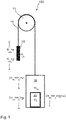
- a cable elevator system 100 is shown schematically, in which an elevator car 18 is connected to a counterweight 16 via a cable 14 .
- the cable 14 is guided over a traction sheave 12 which is driven by a drive motor (not shown) in order to move the elevator car 18 up and down.
- a schematically illustrated elevator load 20 is arranged in the elevator car 18 .
- the elevator car 18 has a weight m FK , and the elevator load 20 located therein has an additional weight m L. These weights are guided via the cable 14 to the counterweight 16, which has the mass m GG .
- the total mass of the system is carried by the traction sheave 12.
- the mass of the counterweight m GG corresponds to the value of the mass m FK of the elevator plus approximately 50% of the nominal load that the elevator car is intended to transport, and thus compensates for an average load on the elevator car.
- the total force of the elevator car 18 with mass 20 is thus given by ( m Fk + m L ) * (g +a).
- the counterweight with the weight force m GG * g acts downwards and the opposing force m GG * a acts upwards.
- a safety gear 266, comprising two safety brakes 26a, 26b, can brake the elevator car 18, which is guided by guide rollers 24a, 24b along an elevator car guide 22, in an emergency. If the braking deceleration a catch that can be exerted by the safety gear 26a, 26b is greater than the gravitational acceleration g, the counterweight 16 would be thrown upwards if the safety gear 26 were to be gripped and would move a distance ⁇ s higher than that would be possible with the taut rope 14 .
- the elevator car 18 In the case of a flying counterweight 16, only the elevator car 18 is braked by the safety gear 26, without the influence of the counterweight 16 playing a role. Since the elevator car 18 is decelerated with significantly more than the gravitational acceleration a Fang> 1g, the counterweight 16 is in free parabolic flight with an initial speed in the upward direction.
- the flight altitude can be determined by a combination of a distance measurement, for example a laser measurement device for determining the distance s from the elevator shaft pit space 28 to the car 18 and an acceleration measurement on the counterweight 16 .
- the load on the elevator system is significantly higher than in the conventional load test, whereby a proof of strength can be provided, which is achieved by setting a test speed higher than the nominal speed with the elevator car 18 unloaded.
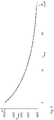
- the energy consumed by safety gears is shown as an example as a function of the braking deceleration applied by the safety gear, provided that the braking deceleration varies from 8 to 28 m/s 2 .
- weak safety gears which can only provide a small braking deceleration, have to dissipate significantly more braking energy than strong safety gears, which can carry out an abrupt braking process.
- the deceleration force is included in inverse proportion, with a weak safety gear having to dissipate 50% more energy than a strong safety gear.
- testing the safety gear with an overload can lead to an overload of the entire system and the safety gear.
- no comparable results are achieved since the influence of the counterweight is included.
- the deceleration performance of the safety gear and the energy consumed can be determined directly.
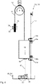
- a first exemplary embodiment of a measuring device 10 is shown.
- the distance s is determined by an optical measuring beam 48 of an optical distance measuring device 30, which is arranged in the pit shaft space 28 as a fixed point 58.
- the optical measuring beam 48 is a frequency-pulsed laser beam and is reflected on an optical reflector 38 which is mounted on the underside of the elevator car 18 .
- the distance measuring device measures its propagation times or phase position, so that precise distance information and thus also speed and also acceleration information is determined as a time derivation of the distance values of the elevator car 18 can become.
- Adjusting means 40 are attached to the distance measuring device 56 for an exact alignment of the measuring beam 48 in order to be able to align the measuring device with respect to the reflector 38 .
- An accelerometer sensor 32 is arranged on the counterweight 16 and can transmit acceleration values measured in real time to the distance measuring device 56 by means of a radio antenna 34 .
- the distance measuring device includes an analysis device that uses the acceleration values of the counterweight 16 and the distance s of the elevator car 18 determined by the measuring beam 48 to determine a relative position of the counterweight to the elevator car, and can determine braking deceleration and the arresting energy of the arresting device 26.
- FIG 5 an exemplary embodiment of a measuring device 10 is shown schematically in a block circuit diagram.
- This includes a distance measuring device 56, which is designed as an optical distance measuring device 30 and which can determine the distance to an elevator car 18 or to a counterweight 16 from a fixed point 58, for example a pit space 28, by means of an optical measuring beam 48.
- the distance measuring device 56 is connected to a relative position detection device 52 which can determine the relative position ⁇ s between the counterweight 16 and the elevator car 18 .
- An acceleration sensor 32 which can detect a vertical acceleration component of the counterweight 16 or the elevator car 18, can be temporarily connected to this via a contact device 68, for example a USB connection.
- the characteristic value K in particular the deceleration values of the safety gear 26 or the braking energy absorbed by the safety gear 26, can be determined using an analysis device 54.
- a force measuring device 46 can also be connected to the analysis device 54 via a USB connection 68 and a two-axis gyrometer 36 or a two-axis acceleration sensor can also be temporarily connected via a contact device 68 for data synchronization and, if necessary, for battery charging.
- the data values received from the sensors 32, 36 and 46 can be taken into account in the analysis in a post-processing method, with time-based values, such as the values of the vertical acceleration sensor 32 or the position sensors 36, being chronologically brought into line with the distance values of the distance measuring device 56 by means of a cross-correlation. in order to be able to simulate and analyze the transient motion sequence.
- the masses of counterweight 16 or elevator car 18 which are necessary for determining the braking energy of the safety gear 26 can be determined by means of the force measuring device 46 .
- Torsion of the elevator car 18 during braking can be determined by the gyrometer 36 in order to be able to identify uneven behavior of individual safety gears 26 .
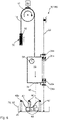
- the distance between the elevator car 18 and the elevator shaft pit area 28 is determined as a fixed point 58 by means of an optical distance measuring device 56 .
- the mass of the counterweight 16 can be determined by load cells 46a, and the mass of the elevator car 18 can be determined from a set of load cells 46b, which are arranged on buffers 42 for spring-loading the car 18.
- the masses of counterweight 16 and elevator car 18 can thus be determined exactly, independently of stored elevator system data, so that calculation of characteristic value K is also possible without knowledge of stored elevator data.
- the force-measuring devices 46b can be used, for example, to calibrate a load scale 50 that is located in the elevator car 18 .
- a load scale 50 that is located in the elevator car 18 .
- successive additional weights 20 are loaded into the elevator car 18, and to calibrate the function and display of the force measuring device 50.
- a linearity and hysteresis error in the load scale 50 can thus be determined.
- a measuring method can be carried out in which the elevator car 18 is driven onto the force measuring devices 46b of the buffers 42 at different speeds.
- the acceleration sensor 32 on the counterweight 16 has an online data store and stores acceleration values with its own time base. After completion of the measurement process, an analysis of the dynamic behavior of the elevator system can be carried out by a cross-correlation of the acceleration values of the sensor 32 with distance values s, which are recorded by the distance measuring devices 56 .
- FIG. 7 Another variant of a measuring system 10 is shown, in which two optically scanned distance values from the elevator car 18 and the counterweight 16 are recorded by means of two optical distance measuring devices 30 instead of an acceleration value.
- reflector mirrors 38a, 38b are arranged on the underside of the elevator car 18 and the counterweight 16, and two optical distance measuring devices 56, which are connected to one another via a data connection line, independently determine the distances from the counterweight 16 and elevator car 18 to the elevator shaft pit space.
- the position, speed and acceleration of the two components of the cable system 100 can be determined synchronously and the effectiveness of the safety gear 26 and the brake 60 can be determined.
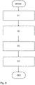
- a safety catch force F safety is determined at a nominal speed v nominal in a descent of an unloaded elevator car 18 with an empty weight m FK in a first step S1.
- the safety gear 26 is triggered by the overspeed or manually, resulting in a braking deceleration a catch_empty >1 g, so that the counterweight 16 is in free parabolic flight upwards.
- an increased test speed v test is determined by analyzing the braking deceleration a catch_leer , at which a predetermined test load occurs with the catch device 26 of the rope elevator 100.
- v test v 140%
- ie at 140% of the nominal speed v nom with an unloaded elevator car with an empty weight m FK_Leer
- a relative change in position ⁇ s of elevator car 18 and counterweight 16 being recorded to determine whether the expected deceleration values are met and the corresponding energies and loads occur.
- an assessment is made as to whether the recorded change in relative position ⁇ s is sufficient to reach the predetermined test load of the elevator 100, and the characteristic value K is determined.
- the effectiveness of the service brake 60 can be assessed in the upward direction when the driver's cabin 18 is empty, as in the downward direction with a driver's cabin 18 loaded with a nominal load 20 . Furthermore, the status of the elevator buffers 42 can be determined and a buffer characteristic curve can be established.
- the state of the safety gear 26 can thus be checked without additional weights being supplied and with little personnel and technical effort, and this can be determined independently of the design of the elevator system 100 .
Landscapes
- Maintenance And Inspection Apparatuses For Elevators (AREA)
- Indicating And Signalling Devices For Elevators (AREA)
Claims (19)
- Système de mesure (10) pour déterminer une énergie d'arrêt E Fang d'un dispositif de freinage (26) d'un ascenseur à câbles (100), lequel est relié à un contrepoids (16) au moyen d'un câble (14), comprenant au moins un dispositif de mesure de distance (56) pour déterminer une distance s d'une cabine d'ascenseur (18) et/ou du contrepoids (16) par rapport à un point fixe (58), sachant que le système de mesure (10) comprend un second dispositif de mesure de distance (56) et/ou un capteur d'accélération (32), un dispositif de détection de position relative (52) pour détecter un changement de position relative Δs entre la cabine d'ascenseur (18) et le contrepoids (16) à la fin d'une descente de la cabine d'ascenseur (18) en raison de l'action de freinage du dispositif de freinage (26), et un dispositif d'analyse (54) pour déterminer l'énergie d'arrêt E Fang, lorsque la cabine d'ascenseur (18) et le contrepoids (16) ont atteint l'arrêt sur la base de l'évolution du changement de position relative Δs entre la cabine d'ascenseur (18) et le contrepoids (16).
- Système (10) selon la revendication 1, caractérisé en ce que le dispositif de mesure de distance (56) est un dispositif de mesure de distance optique (30) qui est disposé au point fixe (58) et dont le faisceau de mesure optique (48) est réfléchi par un réflecteur optique (38) sur une surface inférieure ou supérieure de la cabine d'ascenseur (18) et/ou du contrepoids (16).
- Système (10) selon la revendication 1 ou 2, caractérisé en ce que le dispositif de mesure de distance (56) comprend un dispositif de mesure de distance (30) basé sur un capteur d'accélération ou une caméra, ledit dispositif détectant un changement de distance à partir du point fixe (58) suite à une mesure d'accélération ou au moyen d'une reconnaissance de données d'image.
- Système (10) selon l'une des revendications précédentes, caractérisé en ce qu'un capteur d'accélération (32) disposé sur le contrepoids (16) est inclus et que le dispositif de mesure de distance (56) est agencé pour mesurer la distance s entre la cabine d'ascenseur (18) et le point fixe (58), et le dispositif de détection de la position relative (52) est agencé pour déterminer le changement de position relative Δs sur la base de l'évolution de la distance s de la cabine d'ascenseur (18) par rapport au point fixe (28) et une valeur d'accélération a GG du capteur d'accélérations (32) disposé sur le contrepoids (16).
- Système (10) selon l'une des revendications précédentes, caractérisé en ce qu'un gyromètre (36) et/ou un capteur d'accélération (32) est disposé sur la cabine d'ascenseur (16) pour déterminer un basculement de la cabine d'ascenseur (16), et que le dispositif d'analyse (54) est agencé pour déterminer une action de freinage irrégulière du dispositif de freinage (26) sur la base du basculement déterminé.
- Système (10) selon l'une des revendications précitées, caractérisé en ce que le capteur d'accélération (32) et/ou le gyromètre (36) et le dispositif de mesure de distance (56) comprennent une mémoire de données interne pour l'enregistrement temporel des valeurs de mesure, sachant que le dispositif d'analyse (54) est agencé pour effectuer une association temporelle des valeurs de mesure du capteur d'accélération (32) et/ou du gyromètre (36) et du dispositif de mesure de distance (56) au moyen d'une corrélation croisée pour déterminer l'énergie d'arrêt E Fang à la fin d'une opération de mesure.
- Système (10) selon la revendication 6, caractérisé en ce que le capteur d'accélération (32) et/ou le gyromètre (36) peuvent être reliés temporairement au dispositif d'analyse (54) via une unité de contact (68) pour un échange de données, sachant que le dispositif d'analyse (54) est inclus dans le dispositif de mesure de distance (56) conçu sous forme d'un appareil transportable.
- Système (10) selon l'une des revendications 1 à 5 précitées, caractérisé en ce qu'une transmission de données entre le capteur d'accélération (32) et/ou le gyromètre (36) et le dispositif de mesure de distance (56) s'effectue sans fil par transmission radio via des antennes radio (34).
- Système (10) selon l'une des revendications précitées, caractérisé en ce qu'il comprend au moins un, en particulier plusieurs dispositifs de mesure de force (46), lesquels sont agencés pour mesurer une force de poids m FK de la cabine d'ascenseur (18) et/ou une force de poids m GG du contrepoids (16), et qui sont reliés au dispositif d'analyse (54) pour déterminer l'énergie d'arrêt E Fang du dispositif de freinage (26).
- Procédé de caractérisation d'un dispositif de freinage (26) d'un ascenseur à câbles (100), en utilisant un système (10) selon l'une des revendications du système précitées, dans lequel ;- au cours d'une première étape (S1), une force d'arrêt F Fang du dispositif de freinage (26) est déterminée à la vitesse nominale v nenn d'une descente d'une cabine d'ascenseur (18) non chargée avec un poids à vide m FK, sachant qu'il faut atteindre une décélération de freinage a Fang_leer > 1g ;- au cours d'une deuxième étape (S2), une vitesse de test v test > v nenn est déterminée en fonction de la force d'arrêt F Fang et/ou d'une décélération de freinage a Fang_leer, à laquelle il apparaît une charge d'essai prédéterminable du dispositif de freinage (26) et de l'ascenseur à câbles (100);- au cours d'une troisième étape (S3), un trajet d'essai est effectué à la vitesse de test déterminée v test >v nenn avec une cabine d'ascenseur (18) non chargée et un poids à vide m FK, sachant qu'un changement de position relative Δs de la cabine d'ascenseur (18) par rapport au contrepoids (16) est enregistré ;- au cours d'une quatrième étape (S4), une évaluation est effectuée pour savoir si le changement de position relative Δs enregistré, qui correspond à une charge particulière ou à des forces d'accélération et des énergies de freinage, est suffisant pour atteindre une charge d'essai prédéterminée de l'ascenseur à câbles (100), et si l'énergie d'arrêt recherchée E Fang est déterminée.
- Procédé selon la revendication 10, caractérisé en ce que le changement de position relative Δs de la cabine d'ascenseur (18) par rapport au contrepoids (16) est déterminé par corrélation des valeurs de mesure d'un dispositif optique de mesure de distance (30a), lequel mesure une distance s de la cabine d'ascenseur (18) à partir d'un point fixe (58), et d'un second dispositif de mesure de distance (30b), lequel mesure une distance entre un point fixe (58) et le contrepoids (16) ou un capteur d'accélération (32) disposé sur le contrepoids (16), sachant qu'au cours d'une étape de post-traitement, les valeurs de mesure du mouvement de la cabine d'ascenseur (18) et du contrepoids (16) sont associées dans le temps au moyen d'une corrélation croisée.
- Procédé selon la revendication 10 ou 11, caractérisé en ce que la force d'arrêt déterminée F fang est comparée à une force d'arrêt archivée F fang_old provenant d'une base de donnée, et qu'un écart des forces d'arrêt est déterminé puis évalué.
- Procédé selon l'une des revendications précédentes 10 à 12, caractérisé en ce que, pour déterminer le changement de position relative Δs, au moins une distance s entre la cabine d'ascenseur (18) et/ou le contrepoids (16) et un point de référence fixe (58) est déterminée au moyen d'un dispositif optique de mesure de distance (30).
- Procédé selon l'une des revendications précédentes 10 à 13, caractérisé en ce que, pour déterminer le changement de position relative Δs, au moins une distance s entre la cabine d'ascenseur (18) et/ou le contrepoids (16) et un point de référence fixe (58) est déterminée ou améliorée au moyen d'un dispositif de mesure de distance (30) sur la base d'un capteur d'accélération ou d'une caméra optique.
- Procédé selon l'une des revendications précédentes 10 à 14, caractérisé en ce que, pour déterminer le changement de position relative Δs, au moins une composante d'accélération verticale a FK de la cabine d'ascenseur (18) et/ou a GG du contrepoids (16) est détectée puis évaluée par un capteur d'accélération (32).
- Procédé selon l'une des revendications 10 à 15, caractérisé en ce qu'un mouvement rotatif de la cabine d'ascenseur (18) est détecté au moyen d'un gyromètre (36) ou d'un capteur d'accélération (32) pour déterminer une action irrégulière du dispositif de freinage (26).
- Procédé selon l'une des revendications 10 à 16, caractérisé en ce que, pour déterminer la force de poids m FK de la cabine d'ascenseur (18) et/ou la force de poids m GG du contrepoids (16), au moins un dispositif de mesure de force (46) mesure la force de poids en faisant descendre la cabine d'ascenseur (18) et/ou le contrepoids (16) sur un tampon (42, 44).
- Procédé selon la revendication 17, caractérisé en ce qu'une balance de charge (50) de l'ascenseur à câbles (100) est calibrée au cours d'une étape supplémentaire, sachant qu'un calibrage de la balance de charge (50) est effectué par une charge croissante de la cabine d'ascenseur (18) ainsi qu'un enregistrement de la force de poids de la cabine d'ascenseur - par le dispositif de mesure de force (46) - et de la balance de charge (50).
- Procédé selon l'une des revendications précédentes 10 à 18, caractérisé en ce que, au cours d'une étape supplémentaire, une valeur caractéristique d'un frein de service (60) est déterminée par un déplacement de la cabine d'ascenseur (18) non chargée en analysant l'évolution de la distance s entre la cabine d'ascenseur (18) et le point fixe (58).
Priority Applications (1)
| Application Number | Priority Date | Filing Date | Title |
|---|---|---|---|
| HRP20221153TT HRP20221153T1 (hr) | 2014-02-05 | 2015-02-05 | Mjerni sustav i mjerna metoda za ispitivanje sigurnosne opreme dizala |
Applications Claiming Priority (2)
| Application Number | Priority Date | Filing Date | Title |
|---|---|---|---|
| DE102014101381.6A DE102014101381B4 (de) | 2014-02-05 | 2014-02-05 | Messsystem und Messverfahren zur Prüfung der Fangvorrichtung eines Aufzugs |
| PCT/EP2015/052403 WO2015118064A1 (fr) | 2014-02-05 | 2015-02-05 | Système et procédé de mesure pour vérifier le dispositif d'arrêt d'un ascenseur |
Publications (2)
| Publication Number | Publication Date |
|---|---|
| EP3102523A1 EP3102523A1 (fr) | 2016-12-14 |
| EP3102523B1 true EP3102523B1 (fr) | 2022-06-22 |
Family
ID=52464382
Family Applications (1)
| Application Number | Title | Priority Date | Filing Date |
|---|---|---|---|
| EP15703560.1A Active EP3102523B1 (fr) | 2014-02-05 | 2015-02-05 | Système et procédé de mesure pour vérifier le dispositif d'arrêt d'un ascenseur |
Country Status (6)
| Country | Link |
|---|---|
| EP (1) | EP3102523B1 (fr) |
| DE (1) | DE102014101381B4 (fr) |
| DK (1) | DK3102523T3 (fr) |
| ES (1) | ES2922181T3 (fr) |
| HR (1) | HRP20221153T1 (fr) |
| WO (1) | WO2015118064A1 (fr) |
Families Citing this family (30)
| Publication number | Priority date | Publication date | Assignee | Title |
|---|---|---|---|---|
| WO2017115100A1 (fr) * | 2015-12-28 | 2017-07-06 | Otis Elevator Company | Surveillance et réglage de réserve de système d'ascenseur |
| US10577221B2 (en) | 2017-05-12 | 2020-03-03 | Otis Elevator Company | Imaging inspection systems and methods for elevator landing doors |
| US10577222B2 (en) | 2017-05-12 | 2020-03-03 | Otis Elevator Company | Coded elevator inspection and positioning systems and methods |
| EP3401261B1 (fr) | 2017-05-12 | 2021-02-24 | Otis Elevator Company | Systèmes et procédés d'inspection d'ascenseur automatiques |
| US10479648B2 (en) | 2017-05-12 | 2019-11-19 | Otis Elevator Company | Automatic elevator inspection systems and methods |
| US11034545B2 (en) | 2018-03-26 | 2021-06-15 | Otis Elevator Company | Method and system for brake testing an elevator car |
| CN108358010A (zh) * | 2018-04-04 | 2018-08-03 | 安徽中安检测中心有限公司 | 一种齿轮锥鼓型渐进式安全防坠器测试台 |
| US12459780B2 (en) * | 2018-06-27 | 2025-11-04 | Inventio Ag | Method and system for determining the position of an elevator car of an elevator installation |
| CN108996347A (zh) * | 2018-09-23 | 2018-12-14 | 德州市产品检验检测研究院 | 一种测量电梯制停距离的测量装置及其测量方法 |
| CN109650206B (zh) * | 2019-01-24 | 2024-04-05 | 大连特种设备检验检测研究院有限公司 | 一种电梯负载安全制动试验装置 |
| CN111747252A (zh) * | 2019-03-26 | 2020-10-09 | 福州特设云服信息技术有限公司 | 一种电梯制动距离的检测方法 |
| US11718504B2 (en) * | 2019-05-28 | 2023-08-08 | His Majesty The King In Right Of Canada, As Represented By The Minister Of Natural Resources | Inertial analyzer for vertical mining conveyances and method thereof |
| CN111256546B (zh) * | 2020-01-23 | 2022-08-09 | 西安现代控制技术研究所 | 拖曳式二次起爆云爆弹放缆装置动态性能地面测试系统 |
| DE112020006689T5 (de) | 2020-02-07 | 2022-12-08 | Mitsubishi Electric Building Solutions Corporation | Diagnosevorrichtung und Diagnoseanalysevorrichtung für Vertikaltransportvorrichtungen |
| DE102020203525A1 (de) | 2020-03-19 | 2021-09-23 | Thyssenkrupp Elevator Innovation And Operations Ag | Verfahren zum Überprüfen einer Fangvorrichtung für einen Aufzug |
| EP4263409A1 (fr) * | 2020-12-16 | 2023-10-25 | Inventio Ag | Procédé et dispositif de commande pour déterminer des informations concernant l'emplacement actuel d'une cabine dans la cage d'un ascenseur |
| CN112660955A (zh) * | 2020-12-28 | 2021-04-16 | 福建省特种设备检验研究院泉州分院 | 一种电梯125%载荷试验方法 |
| CN112607551B (zh) * | 2020-12-30 | 2024-09-27 | 菱王电梯有限公司 | 一种电梯安全钳试验装置、其试验方法及其实训考核方法 |
| CN114295402B (zh) * | 2021-12-31 | 2024-05-07 | 水利部水工金属结构质量检验测试中心 | 一种卷扬式启闭机试验系统 |
| CN114538230B (zh) * | 2022-01-10 | 2024-01-02 | 衢州市特种设备检验中心 | 一种电梯125%载荷下行制动性能的检测方法及系统 |
| CN114920118B (zh) * | 2022-05-31 | 2023-09-19 | 中国矿业大学 | 一种基于钢丝绳张力的立井箕斗卸载残留预警系统及识别方法 |
| CN116040443B (zh) * | 2022-12-30 | 2025-09-12 | 广东机电职业技术学院 | 一种扶梯刹车特征参数测量装置及方法 |
| DE102023109710B4 (de) * | 2023-04-18 | 2025-02-06 | Tsg Technische Service Gesellschaft Mbh | Verfahren zum Betreiben einer Aufzugsanlage, Computereinrichtung |
| DE102023112418A1 (de) * | 2023-05-11 | 2024-06-06 | TÜV Nord Systems GmbH & Co. KG | Überprüfung von Aufzugsanlagen auf der Grundlage von Geschwindigkeitsmessungen |
| DE102023112419A1 (de) * | 2023-05-11 | 2024-06-06 | TÜV Nord Systems GmbH & Co. KG | Überprüfung von Aufzugsanlagen auf der Grundlage von Abstandsmessungen |
| DE102023113985A1 (de) * | 2023-05-26 | 2024-05-29 | TÜV Nord Systems GmbH & Co. KG | Überprüfung von Aufzugsanlagen auf der Grundlage von Positionsmessungen |
| CN116878846A (zh) * | 2023-07-19 | 2023-10-13 | 广东景呈电力设备有限公司 | 电力高空作业防坠落试验装置及测试方法 |
| CN116773178B (zh) * | 2023-08-16 | 2024-01-05 | 中检集团公信安全科技有限公司 | 矿山防坠器制动距离测量装置及其测量方法 |
| CN117228476B (zh) * | 2023-10-08 | 2025-06-27 | 福建省特种设备检验研究院 | 一种能检测人员坠落底坑的检查装置 |
| CN121757701B (zh) * | 2026-03-05 | 2026-05-01 | 山东省特种设备检验研究院集团有限公司 | 一种电梯轿厢部件承载制动安全运行测试方法及系统 |
Family Cites Families (6)
| Publication number | Priority date | Publication date | Assignee | Title |
|---|---|---|---|---|
| DE9116466U1 (de) * | 1991-03-19 | 1992-12-03 | Base-Electronic GmbH, 2000 Norderstedt | Einrichtung zur Erkennung der momentanen Position, der Beschleunigung od.dgl. eines innerhalb eines Aufzugschachtes verfahrbaren Lasten- und/oder Personenaufzuges |
| DE4217587C2 (de) * | 1992-05-21 | 1999-02-25 | Ernst Dipl Ing Kasten | Anlagen-Diagnoseverfahren |
| DE4444466C1 (de) * | 1994-11-29 | 1996-04-11 | Mannesmann Ag | Verfahren und Einrichtung zum Prüfen der Bremsfunktion eines Hubwerks mit Motor und einer Bremse |
| EP2221268B1 (fr) * | 2009-02-20 | 2014-04-16 | DEKRA e.V. | Procédé et agencement destinés à contrôler la capacité de fonctionnement réglementaire d'un ascenseur |
| DE102009028596A1 (de) * | 2009-08-17 | 2011-03-03 | Dekra Testing & Inspection Gmbh | Verfahren und Anordnung zur Prüfung der ordnungsgemäßen Funktionsfähigkeit eines Aufzugs |
| DE102011076241A1 (de) * | 2011-03-07 | 2012-09-13 | Dekra Industrial Gmbh | Verfahren und Vorrichtung zur Prüfung der ordnungsgemäßen Funktionsfähigkeit eines Aufzugs |
-
2014
- 2014-02-05 DE DE102014101381.6A patent/DE102014101381B4/de active Active
-
2015
- 2015-02-05 HR HRP20221153TT patent/HRP20221153T1/hr unknown
- 2015-02-05 DK DK15703560.1T patent/DK3102523T3/da active
- 2015-02-05 ES ES15703560T patent/ES2922181T3/es active Active
- 2015-02-05 EP EP15703560.1A patent/EP3102523B1/fr active Active
- 2015-02-05 WO PCT/EP2015/052403 patent/WO2015118064A1/fr not_active Ceased
Also Published As
| Publication number | Publication date |
|---|---|
| ES2922181T3 (es) | 2022-09-09 |
| DE102014101381B4 (de) | 2017-08-17 |
| EP3102523A1 (fr) | 2016-12-14 |
| DK3102523T3 (en) | 2022-09-26 |
| HRP20221153T1 (hr) | 2022-11-25 |
| DE102014101381A1 (de) | 2015-08-06 |
| WO2015118064A1 (fr) | 2015-08-13 |
Similar Documents
| Publication | Publication Date | Title |
|---|---|---|
| DE102014101381B4 (de) | Messsystem und Messverfahren zur Prüfung der Fangvorrichtung eines Aufzugs | |
| EP0391174B2 (fr) | Dispositif et méthode pour détecter des paramètres physiques d'un élévateur | |
| EP2683612A1 (fr) | Procédé et dispositif permettant de contrôler le bon fonctionnement d'un ascenseur | |
| DE112013006482T5 (de) | Aufzugsvorrichtung | |
| DE4217587C1 (en) | Diagnosis system for checking lift or conveyor safety - tests braking and emergency blocking systems under simulated loading conditions and records acceleration characteristic | |
| EP2101156B1 (fr) | Procédé et dispositif destinés à la surveillance de systèmes de réglage de châssis | |
| WO2014124890A1 (fr) | Procédé permettant de mettre en œuvre un essai de sauvetage pour ascenseur | |
| DE102009015648A1 (de) | Anordnung zur Durchführung von Wartungsarbeiten an Flugzeugen | |
| DE102015226699A1 (de) | Vorrichtung und Verfahren zur Erfassung wenigstens eines Bewegungsparameters einer triebwerksraumlosen Treibscheibenaufzugsanlage | |
| DE102014220445B4 (de) | Vorrichtung zur Überprüfung von Führungen | |
| EP2650245B1 (fr) | Procédé et agencement destinés à contrôler la capacité de fonctionnement règlementaire d'un ascenseur | |
| DE102017122237A1 (de) | Mobile Sicherheitsprüfvorrichtung zur Prüfung der ordnungsgemäßen Funktionsfähigkeit einer Fangvorrichtung einer seilgeführten Befahranlage | |
| DE102019007039A1 (de) | Steuervorrichtung und Verfahren zum Einrücken einer Fangvorrichtung | |
| WO2009135629A1 (fr) | Mesure de l’accélération dans un dispositif élévateur | |
| DE102017202589A1 (de) | Verfahren und Vorrichtung zur Ermittlung der Treibfähigkeit einer Förderanlage über eine Drehmomentmessung | |
| DE102016204422A1 (de) | Vorrichtung und Verfahren zur Überprüfung einer Lastbegrenzungseinrichtung insb. von einer fördertechnischen Anlage | |
| EP4332039A1 (fr) | Essai d'ascenseur par mesure de la courbe d'accélération | |
| EP3676013A1 (fr) | Dispositif et procédé pour déterminer un paramètre de processus agissant sur une matière dans un système de rotation | |
| CN106017797B (zh) | 一种无人机的惯量测量装置及无人机的惯量测量方法 | |
| WO2018108824A1 (fr) | Poste de sécurité, laboratoire mobile et procédé | |
| WO2004071924A1 (fr) | Procede pour verifier des parachutes | |
| DE202024104301U1 (de) | Aufzugstreibfähigkeitsmesssystem mit über Beschleunigungsmesswerte berechnetem variablem Massenkennwert | |
| EP3103537B1 (fr) | Procede et systeme de mesure destine au diagnostic de dispositifs destines a transporter des charges, utilisation du systeme de mesure | |
| DE102023112419A1 (de) | Überprüfung von Aufzugsanlagen auf der Grundlage von Abstandsmessungen | |
| DE102023109691A1 (de) | Überprüfung von Aufzugsanlagen auf der Grundlage von mehreren Messgrößen |
Legal Events
| Date | Code | Title | Description |
|---|---|---|---|
| REG | Reference to a national code |
Ref country code: HR Ref legal event code: TUEP Ref document number: P20221153 Country of ref document: HR |
|
| PUAI | Public reference made under article 153(3) epc to a published international application that has entered the european phase |
Free format text: ORIGINAL CODE: 0009012 |
|
| STAA | Information on the status of an ep patent application or granted ep patent |
Free format text: STATUS: REQUEST FOR EXAMINATION WAS MADE |
|
| 17P | Request for examination filed |
Effective date: 20160905 |
|
| AK | Designated contracting states |
Kind code of ref document: A1 Designated state(s): AL AT BE BG CH CY CZ DE DK EE ES FI FR GB GR HR HU IE IS IT LI LT LU LV MC MK MT NL NO PL PT RO RS SE SI SK SM TR |
|
| AX | Request for extension of the european patent |
Extension state: BA ME |
|
| DAX | Request for extension of the european patent (deleted) | ||
| STAA | Information on the status of an ep patent application or granted ep patent |
Free format text: STATUS: EXAMINATION IS IN PROGRESS |
|
| 17Q | First examination report despatched |
Effective date: 20190412 |
|
| GRAP | Despatch of communication of intention to grant a patent |
Free format text: ORIGINAL CODE: EPIDOSNIGR1 |
|
| STAA | Information on the status of an ep patent application or granted ep patent |
Free format text: STATUS: GRANT OF PATENT IS INTENDED |
|
| INTG | Intention to grant announced |
Effective date: 20220304 |
|
| GRAS | Grant fee paid |
Free format text: ORIGINAL CODE: EPIDOSNIGR3 |
|
| GRAA | (expected) grant |
Free format text: ORIGINAL CODE: 0009210 |
|
| STAA | Information on the status of an ep patent application or granted ep patent |
Free format text: STATUS: THE PATENT HAS BEEN GRANTED |
|
| AK | Designated contracting states |
Kind code of ref document: B1 Designated state(s): AL AT BE BG CH CY CZ DE DK EE ES FI FR GB GR HR HU IE IS IT LI LT LU LV MC MK MT NL NO PL PT RO RS SE SI SK SM TR |
|
| REG | Reference to a national code |
Ref country code: GB Ref legal event code: FG4D Free format text: NOT ENGLISH |
|
| REG | Reference to a national code |
Ref country code: CH Ref legal event code: EP |
|
| REG | Reference to a national code |
Ref country code: DE Ref legal event code: R096 Ref document number: 502015015913 Country of ref document: DE |
|
| REG | Reference to a national code |
Ref country code: AT Ref legal event code: REF Ref document number: 1499671 Country of ref document: AT Kind code of ref document: T Effective date: 20220715 |
|
| REG | Reference to a national code |
Ref country code: IE Ref legal event code: FG4D Free format text: LANGUAGE OF EP DOCUMENT: GERMAN |
|
| REG | Reference to a national code |
Ref country code: NL Ref legal event code: FP |
|
| REG | Reference to a national code |
Ref country code: ES Ref legal event code: FG2A Ref document number: 2922181 Country of ref document: ES Kind code of ref document: T3 Effective date: 20220909 |
|
| REG | Reference to a national code |
Ref country code: FI Ref legal event code: FGE |
|
| REG | Reference to a national code |
Ref country code: DK Ref legal event code: T3 Effective date: 20220921 |
|
| REG | Reference to a national code |
Ref country code: SE Ref legal event code: TRGR |
|
| REG | Reference to a national code |
Ref country code: LT Ref legal event code: MG9D |
|
| PG25 | Lapsed in a contracting state [announced via postgrant information from national office to epo] |
Ref country code: LT Free format text: LAPSE BECAUSE OF FAILURE TO SUBMIT A TRANSLATION OF THE DESCRIPTION OR TO PAY THE FEE WITHIN THE PRESCRIBED TIME-LIMIT Effective date: 20220622 Ref country code: GR Free format text: LAPSE BECAUSE OF FAILURE TO SUBMIT A TRANSLATION OF THE DESCRIPTION OR TO PAY THE FEE WITHIN THE PRESCRIBED TIME-LIMIT Effective date: 20220923 Ref country code: BG Free format text: LAPSE BECAUSE OF FAILURE TO SUBMIT A TRANSLATION OF THE DESCRIPTION OR TO PAY THE FEE WITHIN THE PRESCRIBED TIME-LIMIT Effective date: 20220922 |
|
| REG | Reference to a national code |
Ref country code: NO Ref legal event code: T2 Effective date: 20220622 |
|
| REG | Reference to a national code |
Ref country code: SK Ref legal event code: T3 Ref document number: E 40367 Country of ref document: SK |
|
| REG | Reference to a national code |
Ref country code: HR Ref legal event code: T1PR Ref document number: P20221153 Country of ref document: HR |
|
| PG25 | Lapsed in a contracting state [announced via postgrant information from national office to epo] |
Ref country code: RS Free format text: LAPSE BECAUSE OF FAILURE TO SUBMIT A TRANSLATION OF THE DESCRIPTION OR TO PAY THE FEE WITHIN THE PRESCRIBED TIME-LIMIT Effective date: 20220622 Ref country code: LV Free format text: LAPSE BECAUSE OF FAILURE TO SUBMIT A TRANSLATION OF THE DESCRIPTION OR TO PAY THE FEE WITHIN THE PRESCRIBED TIME-LIMIT Effective date: 20220622 |
|
| PG25 | Lapsed in a contracting state [announced via postgrant information from national office to epo] |
Ref country code: SM Free format text: LAPSE BECAUSE OF FAILURE TO SUBMIT A TRANSLATION OF THE DESCRIPTION OR TO PAY THE FEE WITHIN THE PRESCRIBED TIME-LIMIT Effective date: 20220622 Ref country code: RO Free format text: LAPSE BECAUSE OF FAILURE TO SUBMIT A TRANSLATION OF THE DESCRIPTION OR TO PAY THE FEE WITHIN THE PRESCRIBED TIME-LIMIT Effective date: 20220622 Ref country code: PT Free format text: LAPSE BECAUSE OF FAILURE TO SUBMIT A TRANSLATION OF THE DESCRIPTION OR TO PAY THE FEE WITHIN THE PRESCRIBED TIME-LIMIT Effective date: 20221024 Ref country code: EE Free format text: LAPSE BECAUSE OF FAILURE TO SUBMIT A TRANSLATION OF THE DESCRIPTION OR TO PAY THE FEE WITHIN THE PRESCRIBED TIME-LIMIT Effective date: 20220622 |
|
| PG25 | Lapsed in a contracting state [announced via postgrant information from national office to epo] |
Ref country code: PL Free format text: LAPSE BECAUSE OF FAILURE TO SUBMIT A TRANSLATION OF THE DESCRIPTION OR TO PAY THE FEE WITHIN THE PRESCRIBED TIME-LIMIT Effective date: 20220622 Ref country code: IS Free format text: LAPSE BECAUSE OF FAILURE TO SUBMIT A TRANSLATION OF THE DESCRIPTION OR TO PAY THE FEE WITHIN THE PRESCRIBED TIME-LIMIT Effective date: 20221022 |
|
| REG | Reference to a national code |
Ref country code: HR Ref legal event code: ODRP Ref document number: P20221153 Country of ref document: HR Payment date: 20230222 Year of fee payment: 9 |
|
| REG | Reference to a national code |
Ref country code: DE Ref legal event code: R097 Ref document number: 502015015913 Country of ref document: DE |
|
| PG25 | Lapsed in a contracting state [announced via postgrant information from national office to epo] |
Ref country code: AL Free format text: LAPSE BECAUSE OF FAILURE TO SUBMIT A TRANSLATION OF THE DESCRIPTION OR TO PAY THE FEE WITHIN THE PRESCRIBED TIME-LIMIT Effective date: 20220622 |
|
| PLBE | No opposition filed within time limit |
Free format text: ORIGINAL CODE: 0009261 |
|
| STAA | Information on the status of an ep patent application or granted ep patent |
Free format text: STATUS: NO OPPOSITION FILED WITHIN TIME LIMIT |
|
| 26N | No opposition filed |
Effective date: 20230323 |
|
| P01 | Opt-out of the competence of the unified patent court (upc) registered |
Effective date: 20230703 |
|
| PG25 | Lapsed in a contracting state [announced via postgrant information from national office to epo] |
Ref country code: SI Free format text: LAPSE BECAUSE OF FAILURE TO SUBMIT A TRANSLATION OF THE DESCRIPTION OR TO PAY THE FEE WITHIN THE PRESCRIBED TIME-LIMIT Effective date: 20220622 |
|
| PG25 | Lapsed in a contracting state [announced via postgrant information from national office to epo] |
Ref country code: MC Free format text: LAPSE BECAUSE OF FAILURE TO SUBMIT A TRANSLATION OF THE DESCRIPTION OR TO PAY THE FEE WITHIN THE PRESCRIBED TIME-LIMIT Effective date: 20220622 |
|
| GBPC | Gb: european patent ceased through non-payment of renewal fee |
Effective date: 20230205 |
|
| REG | Reference to a national code |
Ref country code: IE Ref legal event code: MM4A |
|
| PG25 | Lapsed in a contracting state [announced via postgrant information from national office to epo] |
Ref country code: GB Free format text: LAPSE BECAUSE OF NON-PAYMENT OF DUE FEES Effective date: 20230205 |
|
| PG25 | Lapsed in a contracting state [announced via postgrant information from national office to epo] |
Ref country code: IE Free format text: LAPSE BECAUSE OF NON-PAYMENT OF DUE FEES Effective date: 20230205 Ref country code: GB Free format text: LAPSE BECAUSE OF NON-PAYMENT OF DUE FEES Effective date: 20230205 |
|
| REG | Reference to a national code |
Ref country code: HR Ref legal event code: ODRP Ref document number: P20221153 Country of ref document: HR Payment date: 20240125 Year of fee payment: 10 |
|
| PG25 | Lapsed in a contracting state [announced via postgrant information from national office to epo] |
Ref country code: BG Free format text: LAPSE BECAUSE OF FAILURE TO SUBMIT A TRANSLATION OF THE DESCRIPTION OR TO PAY THE FEE WITHIN THE PRESCRIBED TIME-LIMIT Effective date: 20220622 |
|
| PG25 | Lapsed in a contracting state [announced via postgrant information from national office to epo] |
Ref country code: BG Free format text: LAPSE BECAUSE OF FAILURE TO SUBMIT A TRANSLATION OF THE DESCRIPTION OR TO PAY THE FEE WITHIN THE PRESCRIBED TIME-LIMIT Effective date: 20220622 |
|
| REG | Reference to a national code |
Ref country code: HR Ref legal event code: ODRP Ref document number: P20221153 Country of ref document: HR Payment date: 20250226 Year of fee payment: 11 |
|
| PGFP | Annual fee paid to national office [announced via postgrant information from national office to epo] |
Ref country code: LU Payment date: 20250218 Year of fee payment: 11 |
|
| PGFP | Annual fee paid to national office [announced via postgrant information from national office to epo] |
Ref country code: HR Payment date: 20250226 Year of fee payment: 11 |
|
| PGFP | Annual fee paid to national office [announced via postgrant information from national office to epo] |
Ref country code: DK Payment date: 20250219 Year of fee payment: 11 |
|
| PGFP | Annual fee paid to national office [announced via postgrant information from national office to epo] |
Ref country code: SE Payment date: 20250219 Year of fee payment: 11 |
|
| PGFP | Annual fee paid to national office [announced via postgrant information from national office to epo] |
Ref country code: NO Payment date: 20250218 Year of fee payment: 11 |
|
| PGFP | Annual fee paid to national office [announced via postgrant information from national office to epo] |
Ref country code: CH Payment date: 20250301 Year of fee payment: 11 |
|
| PGFP | Annual fee paid to national office [announced via postgrant information from national office to epo] |
Ref country code: CZ Payment date: 20250220 Year of fee payment: 11 Ref country code: FR Payment date: 20250219 Year of fee payment: 11 |
|
| PGFP | Annual fee paid to national office [announced via postgrant information from national office to epo] |
Ref country code: SK Payment date: 20250225 Year of fee payment: 11 Ref country code: IT Payment date: 20250228 Year of fee payment: 11 |
|
| PG25 | Lapsed in a contracting state [announced via postgrant information from national office to epo] |
Ref country code: CY Free format text: LAPSE BECAUSE OF FAILURE TO SUBMIT A TRANSLATION OF THE DESCRIPTION OR TO PAY THE FEE WITHIN THE PRESCRIBED TIME-LIMIT; INVALID AB INITIO Effective date: 20150205 |
|
| PG25 | Lapsed in a contracting state [announced via postgrant information from national office to epo] |
Ref country code: HU Free format text: LAPSE BECAUSE OF FAILURE TO SUBMIT A TRANSLATION OF THE DESCRIPTION OR TO PAY THE FEE WITHIN THE PRESCRIBED TIME-LIMIT; INVALID AB INITIO Effective date: 20150205 |
|
| PG25 | Lapsed in a contracting state [announced via postgrant information from national office to epo] |
Ref country code: TR Free format text: LAPSE BECAUSE OF FAILURE TO SUBMIT A TRANSLATION OF THE DESCRIPTION OR TO PAY THE FEE WITHIN THE PRESCRIBED TIME-LIMIT Effective date: 20220622 |
|
| PGFP | Annual fee paid to national office [announced via postgrant information from national office to epo] |
Ref country code: NL Payment date: 20260218 Year of fee payment: 12 |
|
| PGFP | Annual fee paid to national office [announced via postgrant information from national office to epo] |
Ref country code: ES Payment date: 20260319 Year of fee payment: 12 |
|
| PGFP | Annual fee paid to national office [announced via postgrant information from national office to epo] |
Ref country code: DE Payment date: 20260224 Year of fee payment: 12 |
|
| PGFP | Annual fee paid to national office [announced via postgrant information from national office to epo] |
Ref country code: AT Payment date: 20260216 Year of fee payment: 12 |
|
| PGFP | Annual fee paid to national office [announced via postgrant information from national office to epo] |
Ref country code: FI Payment date: 20260217 Year of fee payment: 12 Ref country code: BE Payment date: 20260218 Year of fee payment: 12 |