EP3102748B1 - Abdeckrost - Google Patents
Abdeckrost Download PDFInfo
- Publication number
- EP3102748B1 EP3102748B1 EP15701992.8A EP15701992A EP3102748B1 EP 3102748 B1 EP3102748 B1 EP 3102748B1 EP 15701992 A EP15701992 A EP 15701992A EP 3102748 B1 EP3102748 B1 EP 3102748B1
- Authority
- EP
- European Patent Office
- Prior art keywords
- edge rails
- girders
- cross girders
- grating
- grating according
- Prior art date
- Legal status (The legal status is an assumption and is not a legal conclusion. Google has not performed a legal analysis and makes no representation as to the accuracy of the status listed.)
- Active
Links
Images

Classifications
-
- E—FIXED CONSTRUCTIONS
- E03—WATER SUPPLY; SEWERAGE
- E03F—SEWERS; CESSPOOLS
- E03F5/00—Sewerage structures
- E03F5/04—Gullies inlets, road sinks, floor drains with or without odour seals or sediment traps
- E03F5/06—Gully gratings
-
- E—FIXED CONSTRUCTIONS
- E03—WATER SUPPLY; SEWERAGE
- E03F—SEWERS; CESSPOOLS
- E03F5/00—Sewerage structures
- E03F5/04—Gullies inlets, road sinks, floor drains with or without odour seals or sediment traps
-
- E—FIXED CONSTRUCTIONS
- E04—BUILDING
- E04C—STRUCTURAL ELEMENTS; BUILDING MATERIALS
- E04C2/00—Building elements of relatively thin form for the construction of parts of buildings, e.g. sheet materials, slabs, or panels
- E04C2/30—Building elements of relatively thin form for the construction of parts of buildings, e.g. sheet materials, slabs, or panels characterised by the shape or structure
- E04C2/42—Gratings; Grid-like panels
- E04C2/421—Gratings; Grid-like panels made of bar-like elements, e.g. bars discontinuous in one direction
- E04C2/422—Gratings; Grid-like panels made of bar-like elements, e.g. bars discontinuous in one direction with continuous bars connecting at crossing points of the grid pattern
- E04C2/423—Gratings; Grid-like panels made of bar-like elements, e.g. bars discontinuous in one direction with continuous bars connecting at crossing points of the grid pattern with notches
-
- E—FIXED CONSTRUCTIONS
- E03—WATER SUPPLY; SEWERAGE
- E03F—SEWERS; CESSPOOLS
- E03F5/00—Sewerage structures
- E03F5/04—Gullies inlets, road sinks, floor drains with or without odour seals or sediment traps
- E03F5/06—Gully gratings
- E03F2005/065—Gully gratings with elastic locking elements
Definitions
- the invention relates to a cover grating according to the preamble of claim 1.
- Cover gratings are used to cover openings in surfaces that are to be walked on and / or driven on. A significant proportion of such structures are drainage channels or shafts that serve for surface drainage. Such cover gratings must on the one hand be stable and on the other hand offer a sufficiently high drainage capacity. Other important points are the price and weight.
- cover gratings which are located in areas used by pedestrians, is slip resistance. Problems often arise here when such cover gratings are made from sheet metal for reasons of cost and weight savings.
- a cover grating is known in which mutually crossing bars made of sheet metal material have edges which are designed in the shape of a sawtooth in order to offer increased slip resistance.
- the load-bearing capacity of such grids is limited.
- U cover gratings are known in which longitudinal members with a U-shaped cross-section are mounted with their legs in slots which are located in cross members. The side members protrude over the cross members. The slip resistance of such cover gratings is not sufficient.
- GB 210 69 48 A deals with a grating with longitudinal and transverse girders, the transverse girders being designed as V-shaped, downwardly open profiles with an upper edge.
- the upper edge forms a common step level with the edges of the side members.
- WO 00/03104 A1 describes a grate with U-shaped profiles that are open at the bottom and support the cross members.
- the cross members have an upper edge that is flush with the profiles.
- knobs On the upper edge of the cross member there are knobs that protrude over the U-shaped profiles.
- the invention is based on the object of developing a cover grating of the type mentioned at the outset in such a way that improved slip resistance is ensured with a simple construction.
- a cover grating for covering shafts, gutters or similar structures comprising edge rails, cross members made of sheet metal sections connected to the edge rails and longitudinal members connected to the cross members.
- the longitudinal beams are fastened to the transverse beams in such a way that upper tread surfaces of the longitudinal beams are sunk or run flush at least with the tread sections of the upper edges of the transverse beams.
- This very simple construction has the effect that the tread sections of the cross members, which are in turn made from sheet metal sections, form a non-slip surface, whereby the longitudinal members can in turn be designed in such a way that there is no risk of getting stuck (e.g. with narrow heels).
- the longitudinal members have U-shaped cross-sections, with their legs being fastened in the cross members.
- the edge rails preferably have slots in which the ends of the cross members are inserted. This enables a simple but stable assembly.
- the edge rails are designed as hollow sheet metal profiles, which saves material and weight, but is nevertheless very stable.
- the cross beams have slots for receiving the legs of the longitudinal beams, these slots being designed in such a way that the legs can be inserted into these slots.
- the ends of the crossbeams are preferably bent within the edge rails in such a way that the crossbeams are attached to the edge rails. A stable fastening can therefore be produced solely on the basis of a deformation; welding is not necessary.
- the cross members preferably have stop sections in front of their ends in such a way that the ends can be inserted into the edge rails at a defined insertion depth. This results in an exact shape and dimensioning.
- the edge rails preferably have support surfaces for placing on corresponding sections of the structures, and lower edges of the ends of the crossbeams are shaped in such a way that they rest on the inner surfaces of the support surfaces. This achieves a high level of load stability.
- the tread sections of the cross members have sharp-edged engagement corners opposite the rounded transition areas between the legs and the tread surfaces of the side members. These are of course not so sharp-edged that injuries to people (or bicycle tires) occur, but they are "so angular" that increased slip resistance is guaranteed.
- Retaining clips are preferably provided which are connected to the edge rails for fastening the cover gratings in the building. This ensures a simple but sufficiently stable installation of the cover grating on a building.
- the retaining clips preferably have upper spring sections with which they can be inserted under tension in openings in the edge rails and can be fixed in the edge rails, preferably in a form-fitting manner. The assembly is therefore very simple.
- the edge rails also have downwardly protruding stop elements which are designed to be inserted into corresponding recesses in the structure and to prevent longitudinal displacement of the cover grating relative to the structure. These stop elements can therefore be produced very easily.
- the edge rails have access openings on the outside such that the ends of the crossbeams are accessible from the outside for tools for connecting the crossbeams to the edge rails.
- edge rails 10, 10 ′ are provided, which are connected to one another by cross members 20.
- the cross members 20 have ends 23, 23 'which are inserted into slots 11 of the edge rails 10, 10'.
- the cross members 20 in turn have slots 24 into which legs 32, 32 'of longitudinal members 30 are pressed, which have a U-shaped cross section (like an inverted U).
- Step sections 21, which are sections of the upper edge 22 of each cross member, protrude over upper tread surfaces 31 of the longitudinal members, as shown in particular in FIG Fig. 4 you can see. This ensures that the cross members 20 or their upper edges 22 with the step sections 21 form a very non-slip surface of the cover grating. On the other hand, it is ensured by the longitudinal beams 30 or their upper treads 31 that even with very narrow steps a "break-in" into the drainage openings can hardly happen.
- the cross members 20 also have engagement corners 27 on the tread sections 21 protruding upward between each two longitudinal members, which even if the tread sections 21 run essentially flush with the upper tread surfaces 31 of the longitudinal members 30, still show a slip-inhibiting effect, since the legs 32, 32 'are rounded in their transition areas 33, 33' to the upper step surface 31 and thus a certain cavity is formed into which an elastic shoe sole can penetrate and "hang up" with the engagement corners 27.
- the ends 23, 23 'of the cross members 20 are inserted into the slots 11 of the edge rails 10, 10'.
- These edge rails 10, 10 ' are in turn bent as a partially closed hollow body in such a way that a lower bearing surface 12 is formed with which the edge rails 10, 10' rest on the structure (there on a frame).
- Inner surfaces 13 are formed opposite these bearing surfaces 12 in the interior of the edge rail 10, 10 ', on which, in the assembled state, lower edges 26 of the cross members 20 or the ends 23, 23 'of which rest. This guarantees maximum stability.
- the edge rails 10, 10 ' have access openings 16, 16' on the outside, via which the ends 23, 23 'of the cross members 20 can be bent by means of a tool in such a way that the cross members 20 are fastened in the edge rails 10, 10'.
- a further contributing factor to this is that the cross members 20 have stop sections 25 with which the cross members 10, 10 'stand up at the edges of the slots 11, so that when the ends 23, 23' are bent, the cross members 20 are seated without wobbling in the edge rails 10 , 10 'is guaranteed.
- edge rails 10, 10 ' have openings 14 (see Fig. 7 ), into which retaining clips 40 with upper spring sections 41 can be used, each of which has an engaging projection 43.
- the engagement projection 43 inserts into corresponding recesses in the edge rails 10, 10 'so that the retaining clip 40 can be inserted into the edge rail 10, 10' or its opening 14 and levered in until it snaps into place.
- a clamping section 42 then protrudes downward from the edge rail 10, 10 ', which is designed so that it either hangs on a wall of the building or in an opening provided there and attaches the cover grating to the building.
- the edge rails 10, 10 ' also have stop elements 15, see FIG Fig. 2 , 3 and 4 which engage in corresponding recesses in the structure so that longitudinal displacement of the grate on the structure can be reliably prevented.
Landscapes
- Engineering & Computer Science (AREA)
- Health & Medical Sciences (AREA)
- Life Sciences & Earth Sciences (AREA)
- Hydrology & Water Resources (AREA)
- Public Health (AREA)
- Water Supply & Treatment (AREA)
- Architecture (AREA)
- Civil Engineering (AREA)
- Structural Engineering (AREA)
- Sewage (AREA)
- Heat Treatments In General, Especially Conveying And Cooling (AREA)
- Connection Of Plates (AREA)
- Floor Finish (AREA)
Description
- Die Erfindung betrifft einen Abdeckrost nach dem Oberbegriff des Patentanspruches 1.
- Zum Abdecken von Öffnungen in Oberflächen, die begangen und/oder befahren werden sollen, dienen Abdeckroste. Einen wesentlichen Anteil an derartigen Bauwerken bilden Abflussrinnen oder Schächte, die zur Oberflächenentwässerung dienen. Derartige Abdeckroste müssen zum einen stabil sein, zum anderen eine hinreichend große Entwässerungsleistung bieten. Weitere wichtige Punkte liegen im Preis und im Gewicht.
- Ein weiterer wichtiger Punkt liegt bei Abdeckrosten, die in von Fußgängern begangenen Flächen liegen, in der Rutschsicherheit. Gerade dann, wenn derartige Abdeckroste aus Kostengründen und aus Gründen der Gewichtsersparnis aus Blechmaterial hergestellt werden, treten hier oftmals Probleme auf.
- Aus der
DE 1 856 722 U ist ein Abdeckrost bekannt, bei welchem einander kreuzende Stäbe aus Blechmaterial Kanten aufweisen, die sägezahnförmig ausgebildet sind, um so eine erhöhte Rutschfestigkeit zu bieten. Die Tragfähigkeit derartiger Roste ist begrenzt. - Aus der
DE 1 659 147 A oder derDE 1 966 875 U sind Abdeckroste bekannt, bei denen Längsträger mit U-förmigem Querschnitt mit ihren Schenkeln in Schlitzen gelagert sind, welche sich in Querträgern befinden. Die Längsträger stehen über die Querträger hervor. Die Rutschfestigkeit derartiger Abdeckroste ist nicht hinreichend. -
DE 75 09 303 U beschreibt einen Gitterrost für Rindviehställe mit nach unten geöffneten U-Profilen, die eine vergrößerte Trittfläche für Rinder schaffen. Die U-Profile stehen über die Oberkanten von Trag- und Füllstäben vor und ermöglichen so ein sicheres und schmerzfreies Stehen der Tiere. -
GB 210 69 48 A -
WO 00/03104 A1 - Der Erfindung liegt die Aufgabe zu Grunde, einen Abdeckrost der eingangs genannten Art dahingehend weiterzubilden, dass bei einfacher Konstruktion eine verbesserte Rutschsicherheit gewährleistet ist.
- Diese Aufgabe wird durch einen Abdeckrost zum Abdecken von Schächten, Rinnen oder dergleichen Bauwerken nach Anspruch 1 gelöst, umfassend Randschienen, mit den Randschienen verbundene Querträger aus Blechabschnitten und mit den Querträgern verbundene Längsträger. Hierbei sind die Längsträger derart an den Querträgern befestigt, dass obere Trittflächen der Längsträger versenkt oder bündig mindestens zu Trittabschnitten von Oberkanten der Querträger verlaufen. Durch diese sehr einfache Konstruktion wird bewirkt, dass die Trittabschnitte der Querträger, welche ja wiederum aus Blechabschnitten gefertigt sind, eine rutschfeste Oberfläche bilden, wobei die Längsträger wiederum so ausgebildet sein können, dass keine Gefahr des Hängenbleibens (z.B. mit schmalen Absätzen) gegeben ist.
- Die Längsträger weisen U-förmige Querschnitte auf, wobei ihre Schenkel in den Querträgern befestigt sind. Dadurch kann eine hohe Stabilität bei Erhöhung der oben genannten Sicherheit gegenüber einem Hängenbleiben von dünnen Absätzen gewährleistet sein.
- Die Randschienen weisen vorzugsweise Schlitze auf, in denen Enden der Querträger stecken. Dies ermöglicht eine einfache aber dennoch stabile Montage. Insbesondere sind hierbei die Randschienen als Blech-Hohlprofile ausgebildet, was Material und Gewicht spart, dennoch aber sehr stabil ist.
- Die Querträger weisen Schlitze zur Aufnahme der Schenkel der Längsträger auf, wobei diese Schlitze derart ausgebildet sind, dass die Schenkel in diese Schlitze einsetzbar sind. Auch hier wird mit einfachen konstruktiven Maßnahmen eine hohe Stabilität erwirkt. Die Enden der Querträger sind vorzugsweise innerhalb der Randschienen derart abgebogen, dass die Querträger an den Randschienen befestigt sind. Es kann eine stabile Befestigung also ausschließlich aufgrund einer Verformung hergestellt werden, ein Verschweißen ist nicht notwendig.
- Die Querträger weisen vorzugsweise Anschlagabschnitte vor deren Enden derart auf, dass die Enden in einer definierten Einstecktiefe in die Randschienen einsteckbar sind. Dadurch wird eine exakte Form und Dimensionierung erzielt.
- Die Randschienen weisen vorzugsweise Auflageflächen zum Auflegen auf entsprechende Abschnitte der Bauwerke auf und Unterkanten der Enden der Querträger sind so geformt, dass sie auf den Innenflächen der Auflageflächen aufliegen. Dadurch wird eine hohe Laststabilität erreicht.
- Die Trittabschnitte der Querträger weisen gegenüber abgerundeten Übergangsbereichen zwischen den Schenkeln und den Trittflächen der Längsträger scharfkantige Eingriffsecken auf. Diese sind natürlich nicht so scharfkantig, dass Verletzungen von Personen (oder Fahrradreifen) auftreten, sind aber doch "so eckig", dass eine erhöhte Rutschfestigkeit garantiert wird.
- Es sind vorzugsweise Halteklammern vorgesehen, die zum Befestigen der Abdeckroste im Bauwerk mit den Randschienen verbunden sind. Dadurch ist eine einfache aber doch hinreichend stabile Montage des Abdeckrostes auf einem Bauwerk sichergestellt. Die Halteklammern weisen vorzugsweise obere Federabschnitte auf, mit denen sie in Öffnungen der Randschienen unter Spannung einsetzbar und in den Randschienen vorzugsweise formschlüssig festsetzbar sind. Der Zusammenbau gestaltet sich somit sehr einfach.
- Die Randschienen weisen weiterhin nach unten ragende Stoppelemente auf, die zum Einsetzen in korrespondierende Ausnehmungen im Bauwerk und zum Verhindern einer Längsverschiebung des Abdeckrostes gegenüber dem Bauwerk ausgebildet sind. Diese Stoppelemente können also sehr einfach hergestellt werden.
- Die Randschienen weisen außenseitige Zugangsöffnungen derart auf, dass die Enden der Querträger von außen für Werkzeuge zum Verbinden der Querträger mit den Randschienen zugänglich sind. Durch diese einfache konstruktive Maßnahme werden somit die Abdeckroste sehr leicht herstellbar.
- Nachfolgend wird eine Ausführungsform der Erfindung anhand von Abbildungen näher erläutert. Hierbei zeigen
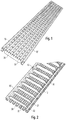
- Fig. 1
- eine perspektivische Darstellung eines Abdeckrostes in einer Ansicht von schräg oben,
- Fig. 2
- den Abdeckrost nach
Fig. 1 in einer Ansicht von schräg unten, - Fig. 3
- eine Draufsicht auf den Abdeckrost nach den
Fig. 1 und 2 , - Fig. 4
- eine Ansicht auf den Abdeckrost nach
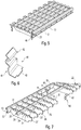
Fig. 3 entlang der Linie IV-IV ausFig. 3 , - Fig. 5
- eine Ausschnittsdarstellung des Abdeckrostes nach den
Fig. 1 und 2 , wobei die Schnittebene entlang der Linie V-V ausFig. 3 verläuft, - Fig. 6
- eine perspektivische Darstellung einer Halteklammer, die bei dem Abdeckrost nach den
Fig. 1-5 Verwendung findet, und - Fig. 7
- eine Darstellung ähnlich der nach
Fig. 5 , wobei eine der Randschienen sowie mehrere der Längsträger und der Querträger zur besseren Verdeutlichung der konstruktiven Situation fortgelassen sind. - In der nachfolgenden Beschreibung werden gleiche und gleich wirkende Teile mit denselben Bezugsziffern bezeichnet.
- Wie aus den Abbildungen hervorgeht, sind Randschienen 10, 10' vorgesehen, die durch Querträger 20 miteinander verbunden sind. Die Querträger 20 weisen Enden 23, 23' auf, welche in Schlitzen 11 der Randschienen 10, 10' stecken.
- Die Querträger 20 wiederum weisen Schlitze 24 auf, in welchen Schenkel 32, 32' von Längsträgern 30 eingepresst sind, die einen U-förmigen Querschnitt (wie ein umgekehrtes U) aufweisen.
- Zwischen jeweils zwei von diesen Längsträgern 30 stehen Trittabschnitte 21, welche Abschnitte der Oberkante 22 eines jeden Querträgers sind, über obere Trittflächen 31 der Längsträger hervor, wie dies insbesondere in
Fig. 4 zu sehen ist. Dadurch ist gewährleistet, dass die Querträger 20 bzw. deren Oberkanten 22 mit den Trittabschnitten 21 eine sehr rutschfeste Oberfläche des Abdeckrostes bilden. Andererseits wird durch die Längsträger 30 bzw. deren obere Trittflächen 31 sichergestellt, dass auch bei sehr schmalen Absätzen ein "Einbrechen" in die Entwässerungsöffnungen kaum passieren kann. - Die Querträger 20 weisen weiterhin an den zwischen jeweils zwei Längsträgern nach oben hervorstehenden Trittabschnitten 21 Eingriffsecken 27 auf, die auch dann, wenn die Trittabschnitte 21 im Wesentlichen bündig zu den oberen Trittflächen 31 der Längsträger 30 verlaufen, noch eine rutschhemmende Wirkung zeigen, da die Schenkel 32, 32' in ihren Übergangsbereichen 33, 33' zur oberen Trittfläche 31 abgerundet sind und somit ein gewisser Hohlraum gebildet wird, in welchen eine elastische Schuhsohle eindringen und sich mit den Eingriffsecken 27 "festhängen" kann.
- Wie weiter oben bereits erwähnt, sind die Enden 23, 23' der Querträger 20 in die Schlitze 11 der Randschienen 10, 10' eingesteckt. Diese Randschienen 10, 10' sind wiederum derart als teilweise geschlossener Hohlkörper gebogen, dass eine untere Auflagefläche 12 gebildet ist, mit welcher die Randschienen 10, 10' auf dem Bauwerk (dort auf einer Zarge) aufliegen. Diesen Auflageflächen 12 im Inneren der Randschiene 10, 10' gegenüber sind Innenflächen 13 gebildet, auf welchen im montierten Zustand wiederum Unterkanten 26 der Querträger 20 bzw. deren Enden 23, 23' aufliegen. Dadurch ist eine maximale Stabilität gewährleistet.
- Die Randschienen 10, 10' weisen außenseitig Zugangsöffnungen 16, 16' auf, über welche mittels eines Werkzeugs die Enden 23, 23' der Querträger 20 derart verbogen werden können, dass die Querträger 20 in den Randschienen 10, 10' befestigt sind. Hierzu trägt weiterhin bei, dass die Querträger 20 Anschlagabschnitte 25 aufweisen, mit welchen die Querträger 10, 10' an den Rändern der Schlitze 11 aufstehen, so dass bei einem Umbiegen der Enden 23, 23' ein wackelfreier Sitz der Querträger 20 in den Randschienen 10, 10' gewährleistet ist.
- Weiterhin weisen die Randschienen 10, 10' Öffnungen 14 (siehe
Fig. 7 ) auf, in welche Halteklammern 40 mit oberen Federabschnitten 41 eingesetzt werden können, welche jeweils einen Eingriffsvorsprung 43 aufweisen. Der Eingriffsvorsprung 43 inseriert in entsprechende Ausnehmungen der Randschienen 10, 10', so dass die Halteklammer 40 in die Randschiene 10, 10' bzw. deren Öffnung 14 hineingesteckt und hineingehebelt werden kann, bis sie dort einschnappt. - In der montierten Position ragt dann ein Klemmabschnitt 42 von der Randschiene 10, 10' nach unten, der so ausgebildet ist, dass er sich entweder an einer Wand des Bauwerks oder in einer dort vorgesehenen Öffnung festhängt und den Abdeckrost auf dem Bauwerk befestigt.
- Die Randschienen 10, 10' weisen weiterhin Stoppelemente 15 auf, siehe
Fig. 2 ,3 und 4 , die in entsprechende Ausnehmungen des Bauwerkes eingreifen, so dass eine Längsverschiebung des Rostes auf dem Bauwerk sicher verhindert werden kann. -
- 10, 10'
- Randschiene
- 11
- Schlitze
- 12
- Auflagefläche
- 13
- Innenfläche
- 14
- Öffnung
- 15
- Stoppelement
- 16, 16'
- Zugangsöffnung
- 20
- Querträger
- 21
- Trittabschnitt
- 22
- Oberkante
- 23, 23'
- Ende
- 24
- Schlitz
- 25
- Anschlagabschnitt
- 26
- Unterkante
- 27
- Eingriffsecke
- 30
- Längsträger
- 31
- Obere Trittfläche
- 32, 32'
- Schenkel
- 33, 33'
- Übergangsbereich
- 40
- Halteklammer
- 41
- Federabschnitt
- 42
- Klemmabschnitt
- 43
- Eingriffsvorsprung
Claims (12)
- Abdeckrost zum Abdecken von Schächten oder Rinnen, umfassend• Randschienen (10, 10'),• mit den Randschienen (10, 10') verbundene Querträger (20) aus Blechabschnitten,• mit den Querträgern (20) verbundene Längsträger (30), die U-förmige Querschnitte mit oberen Trittflächen (31) und in den Querträgern (20) befestigte Schenkel (32, 32') aufweisen,dadurch gekennzeichnet, dass
die Längsträger (30) derart an den Querträgern (20) befestigt sind, dass die oberen Trittflächen (31) der Längsträger (30) versenkt zu Trittabschnitten (21) von oberen Kanten (22) der Querträger (20) verlaufen, diese Trittabschnitte (21) somit über die Trittflächen (31) nach oben hervorstehen. - Abdeckrost nach Anspruch 1, dadurch gekennzeichnet, dass
die Randschienen (10, 10') Schlitze (11) aufweisen, in denen Enden (23, 23') der Querträger (20) stecken. - Abdeckrost nach einem der vorhergehenden Ansprüche, insbesondere nach Anspruch 2,
dadurch gekennzeichnet, dass
die Randschienen (10, 10') als Blech-Hohlprofile ausgebildet sind. - Abdeckrost nach einem der vorhergehenden Ansprüche, insbesondere nach Anspruch 3,
dadurch gekennzeichnet, dass
die Enden (23, 23') der Querträger (20) innerhalb der Randschienen (10, 10') derart abgebogen sind, dass die Querträger (20) an den Randschienen (10, 10') befestigt sind. - Abdeckrost nach einem der vorhergehenden Ansprüche, insbesondere nach Anspruch 2,
dadurch gekennzeichnet, dass
die Querträger (20) Anschlagabschnitte (25) vor den Enden (23, 23') derart aufweisen, dass die Enden (23, 23') in einer definierten Einstecktiefe in die Randschienen (10, 10') einsteckbar sind. - Abdeckrost nach einem der vorhergehenden Ansprüche,
dadurch gekennzeichnet, dass
die Querträger (20) Schlitze (24) zur Aufnahme der Schenkel (32, 32') der Längsträger (30) aufweisen und die Schenkel (32, 32') in diese Schlitze (24) eingepresst sind. - Abdeckrost nach einem der vorhergehenden Ansprüche, insbesondere nach Anspruch 3,
dadurch gekennzeichnet, dass
die Randschienen (10, 10') Auflageflächen (12) zum Auflegen auf entsprechende Abschnitte von Bauwerken aufweisen und Unterkanten (26) der Enden (23, 23') der Querträger (20) auf Innenflächen (13) der Auflageflächen (12) aufliegen. - Abdeckrost nach einem der vorhergehenden Ansprüche,
dadurch gekennzeichnet, dass
die Trittabschnitte (21) der Querträger (20) gegenüber abgerundeten Übergangsbereichen(33, 33') zwischen den Schenkeln (32, 32') und den Trittflächen (31) der Längsträger (30) scharfkantige Eingriffsecken (27) aufweisen. - Abdeckrost nach einem der vorhergehenden Ansprüche,
gekennzeichnet durch Halteklammern (40), die zum Befestigen der Abdeckroste in einem Bauwerk mit den Randschienen (10, 10') verbunden sind. - Abdeckrost nach Anspruch 9,
dadurch gekennzeichnet, dass
die Halteklammern (40) obere Federabschnitte (41) aufweisen, mit denen sie in Öffnungen (14) der Randschienen (10, 10') unter Spannung einsetzbar und in den Randschienen (10, 10') vorzugsweise formschlüssig festsetzbar sind. - Abdeckrost nach einem der vorhergehenden Ansprüche,
dadurch gekennzeichnet, dass
die Randschienen (10, 10') nach unten ragende Stoppelemente (15) aufweisen, die zum Einsetzen in korrespondierende Ausnehmungen in einem Bauwerk und zum Verhindern einer Längsverschiebung des Abdeckrostes gegenüber dem Bauwerk ausgebildet sind. - Abdeckrost nach einem der vorhergehenden Ansprüche,
dadurch gekennzeichnet, dass
die Randschienen (10, 10') außenseitige Zugangsöffnungen (16, 16') derart aufweisen, dass die Enden (23, 23') der Querträger (20) von außen für Werkzeuge zum Verbinden der Querträger (20) mit den Randschienen (10, 10') zugänglich sind.
Priority Applications (1)
| Application Number | Priority Date | Filing Date | Title |
|---|---|---|---|
| PL15701992T PL3102748T3 (pl) | 2014-02-04 | 2015-02-03 | Krata przykrywająca |
Applications Claiming Priority (2)
| Application Number | Priority Date | Filing Date | Title |
|---|---|---|---|
| DE102014101322.0A DE102014101322B4 (de) | 2014-02-04 | 2014-02-04 | Abdeckrost |
| PCT/EP2015/052124 WO2015117932A2 (de) | 2014-02-04 | 2015-02-03 | Abdeckrost |
Publications (2)
| Publication Number | Publication Date |
|---|---|
| EP3102748A2 EP3102748A2 (de) | 2016-12-14 |
| EP3102748B1 true EP3102748B1 (de) | 2021-09-15 |
Family
ID=52440688
Family Applications (1)
| Application Number | Title | Priority Date | Filing Date |
|---|---|---|---|
| EP15701992.8A Active EP3102748B1 (de) | 2014-02-04 | 2015-02-03 | Abdeckrost |
Country Status (14)
| Country | Link |
|---|---|
| US (1) | US20160326735A1 (de) |
| EP (1) | EP3102748B1 (de) |
| CN (1) | CN106103857A (de) |
| AU (2) | AU2015215078A1 (de) |
| CA (1) | CA2938216C (de) |
| DE (1) | DE102014101322B4 (de) |
| ES (1) | ES2900350T3 (de) |
| LT (1) | LT3102748T (de) |
| MX (1) | MX2016009161A (de) |
| NZ (1) | NZ722145A (de) |
| PL (1) | PL3102748T3 (de) |
| RU (1) | RU2667774C1 (de) |
| UA (1) | UA117609C2 (de) |
| WO (1) | WO2015117932A2 (de) |
Families Citing this family (20)
| Publication number | Priority date | Publication date | Assignee | Title |
|---|---|---|---|---|
| US9784028B1 (en) | 2016-05-23 | 2017-10-10 | International Business Machines Corporation | Efficient door assembly |
| JP2019007270A (ja) * | 2017-06-27 | 2019-01-17 | 株式会社中部コーポレーション | グレーチング |
| USD873973S1 (en) * | 2018-10-24 | 2020-01-28 | Ebbe America, Lc | Drain cover |
| DE102018131383A1 (de) * | 2018-12-07 | 2020-06-10 | ACO Severin Ahlmann GmbH & Co Kommanditgesellschaft | Tragstruktur und Verfahren zur Herstellung |
| USD922540S1 (en) | 2019-05-30 | 2021-06-15 | Ebbe America, Lc | Drain cover |
| DE102019115137A1 (de) * | 2019-06-05 | 2020-12-10 | Wiedemann Gmbh | Rost als Abdeckung für eine Abflussrinne |
| USD941966S1 (en) * | 2019-11-13 | 2022-01-25 | Everhard Industries Pty Ltd | Drain grate |
| USD950022S1 (en) * | 2019-11-13 | 2022-04-26 | Everhard Industries Pty Ltd | Drain grate |
| USD941968S1 (en) * | 2019-11-13 | 2022-01-25 | Everhard Industries Pty Ltd | Drain grate |
| DE102020000419B4 (de) | 2020-01-24 | 2022-03-10 | Sven Ifland | Installation zum Sammeln und Ableiten von Abwasser oder Regenwasser |
| USD921166S1 (en) | 2020-01-28 | 2021-06-01 | Ebbe America, Lc | Drain cover |
| USD915565S1 (en) | 2020-01-28 | 2021-04-06 | Ebbe America, Lc | Drain cover |
| USD892276S1 (en) | 2020-01-28 | 2020-08-04 | Ebbe America, Lc | Drain cover |
| USD916250S1 (en) | 2020-02-05 | 2021-04-13 | Ebbe America, Lc | Drain cover |
| AU2021104670B4 (en) * | 2021-06-30 | 2021-12-09 | Stormtech Pty Limited | Grating and method of manufacturing a grating |
| JP7551580B2 (ja) | 2021-08-25 | 2024-09-17 | 株式会社神戸製鋼所 | グレーチングおよびグレーチングの製造方法 |
| CZ309983B6 (cs) * | 2022-09-23 | 2024-04-03 | Horký Jan | Odtoková mřížka |
| USD1066605S1 (en) * | 2023-02-08 | 2025-03-11 | Paddock Pool Equipment Company | Pool grating |
| USD1066606S1 (en) * | 2023-02-08 | 2025-03-11 | Paddock Pool Equipment Company | Pool grating |
| USD1066604S1 (en) * | 2023-02-08 | 2025-03-11 | Paddock Pool Equipment Company | Pool grating |
Family Cites Families (65)
| Publication number | Priority date | Publication date | Assignee | Title |
|---|---|---|---|---|
| US1428230A (en) * | 1921-04-30 | 1922-09-05 | William H Hess | Grating |
| US2128753A (en) * | 1937-03-20 | 1938-08-30 | Lienhard Frederick | Steel floor construction |
| US2305955A (en) * | 1939-08-29 | 1942-12-22 | Dudley Edward Richard | Grating and cover for drains |
| US2384303A (en) * | 1941-03-27 | 1945-09-04 | Smith Corp A O | Welded grating |
| US2396735A (en) * | 1944-04-19 | 1946-03-19 | Air Control Products Inc | Grille |
| US2509732A (en) * | 1946-09-23 | 1950-05-30 | Smith Corp A O | Grating construction |
| US2645985A (en) * | 1950-04-26 | 1953-07-21 | United States Steel Corp | Open floor grating |
| US2834267A (en) * | 1954-01-26 | 1958-05-13 | United States Steel Corp | Grating |
| US2830509A (en) * | 1954-04-20 | 1958-04-15 | Bustin Leopold | Grating |
| FR1123125A (fr) * | 1955-04-27 | 1956-09-18 | Perfectionnement apportés aux caillebotis métalliques | |
| US3156168A (en) * | 1960-04-21 | 1964-11-10 | Reliance Steel Prod Co | Grating |
| DE1856722U (de) | 1962-04-12 | 1962-08-16 | Allendorfer Stahl | Gitterrost zur abdeckung von oeffnungen in fussboeden, treppenstufen u. dgl. |
| US3140644A (en) * | 1962-05-28 | 1964-07-14 | Royal B Lee | Non-skid grating |
| US3308594A (en) * | 1963-06-10 | 1967-03-14 | United States Steel Corp | Slotted panel assembly |
| US3420015A (en) * | 1967-04-12 | 1969-01-07 | Aluminum Plastic Products Corp | Metal grating |
| DE1966875U (de) * | 1967-05-18 | 1967-08-24 | Gitterrost Ges Rudolf Jaeger K | Gitterrost, insbesondere fuer schwemmentmistungsanlagen. |
| DE1659147A1 (de) | 1967-11-17 | 1970-12-23 | Kirchner Gitterrostfabrik Geb | Gitterrost |
| DE1939793A1 (de) | 1968-09-09 | 1970-03-19 | Thermo Bauelement Ag | Waermespeichergeraet |
| US3765136A (en) * | 1970-08-28 | 1973-10-16 | Lionweld Ltd | Grids, gratings or like open work support surfaces or floors |
| US3674149A (en) * | 1970-12-08 | 1972-07-04 | Alton E Donalson | Plumbing grate fixture |
| DE7225074U (de) * | 1972-07-05 | 1972-09-21 | Gerbracht F | Gitterrost |
| US3914911A (en) * | 1973-10-19 | 1975-10-28 | Harold R Paasch | Protective cover for sewer grates |
| US4046482A (en) * | 1975-02-24 | 1977-09-06 | Paasch Harold R | Protective cover for sewer grates |
| DE7509303U (de) * | 1975-03-22 | 1975-07-31 | Lichtgitter Gmbh | Gitterrost für rindviehställe |
| US3948013A (en) * | 1975-05-07 | 1976-04-06 | Lobaugh Lawrence E | Cold forged steel grating |
| US4027451A (en) * | 1976-03-30 | 1977-06-07 | Leopold Bustin | Free flow grating |
| SU702142A1 (ru) * | 1976-07-05 | 1979-12-05 | Всесоюзный Проектно-Конструкторский Технологический Институт Атомного Машиностроения И Котлостроения Впктиатомкотломаш | Решетчатый настил |
| US4051639A (en) * | 1976-08-26 | 1977-10-04 | Syracuse Tank & Manufacturing Co., Inc. | Removable deck for a building structure interstitial space |
| DE2905446C2 (de) * | 1979-02-13 | 1982-12-30 | Eisenwerk Künstler KG, 8750 Aschaffenburg | Gitterrost und Verfahren zu seiner Herstellung |
| US4345998A (en) * | 1979-07-05 | 1982-08-24 | Graffis Kelly R | Plastic catch basin |
| US4282695A (en) * | 1979-07-18 | 1981-08-11 | Lew Hyok S | Self-interlocking grille |
| ATE7937T1 (de) * | 1981-03-19 | 1984-06-15 | Twb-Presswerk Gmbh | Rost fuer entwaesserungsrinnen. |
| GB2106948A (en) * | 1981-09-22 | 1983-04-20 | Brian Harmer | Metal floor-grating |
| US4640643A (en) * | 1985-06-19 | 1987-02-03 | Polydrain, Inc. | Sidewall extension for drain channel system and method for extending the continuous slope of a drainage channel system |
| ES2032874T3 (es) * | 1987-02-02 | 1993-03-01 | Von Roll Ag | Sistema para asegurar una cubierta que cierra una abertura. |
| US4760680A (en) * | 1987-04-27 | 1988-08-02 | Myers Robert E | Fiberglass grating formed of interlocked pultruded fiberglass grating bars |
| US5024550A (en) * | 1989-09-26 | 1991-06-18 | Jack Mainville | Trench grate |
| US5203544A (en) * | 1991-07-09 | 1993-04-20 | Webb A Levan | Cattle guard |
| USD374727S (en) * | 1992-06-09 | 1996-10-15 | IMC/Teddy Food Service Corp. | Floor grate |
| US5529436A (en) * | 1994-05-11 | 1996-06-25 | Tuf-Tite, Inc. | Trench drain system |
| US6112629A (en) * | 1996-01-22 | 2000-09-05 | Mangone; Ronald W. | Weld-free gratings and method and punch and die for forming same |
| WO2000003104A1 (en) * | 1998-07-10 | 2000-01-20 | Owen Lyell Livingston | Modular walkway |
| WO2002035141A1 (en) * | 2000-10-25 | 2002-05-02 | Covington Pte Ltd. | Inter-locking grating |
| ES2298376T3 (es) * | 2001-05-04 | 2008-05-16 | ACO SEVERIN AHLMANN GMBH & CO. KG | Cubierta para un dispositivo de desague. |
| US20020178660A1 (en) * | 2001-05-30 | 2002-12-05 | Lawson Robert B. | Pool grating and a method of installation |
| CN2491515Y (zh) * | 2001-07-24 | 2002-05-15 | 严甘章 | 可止滑的排水沟盖 |
| US6666974B2 (en) * | 2001-11-20 | 2003-12-23 | Ardle E. Page | Subgrate drain basin filter |
| US6942419B2 (en) * | 2002-02-04 | 2005-09-13 | Balco, Inc. | Grate assembly |
| DE20309413U1 (de) * | 2003-06-18 | 2003-09-11 | Steggemann, Franz, 48703 Stadtlohn | Gitterrost |
| DE10328612B4 (de) * | 2003-06-25 | 2009-04-09 | Aco Severin Ahlmann Gmbh & Co. Kg | Oberflächenentwässerungseinrichtung |
| US6908256B1 (en) * | 2004-06-23 | 2005-06-21 | Aco Polymer Products, Inc. | Drainage grate assembly |
| US7121759B2 (en) * | 2004-09-09 | 2006-10-17 | Ohio Gratings, Inc. | Grating system |
| US20060218872A1 (en) * | 2005-03-31 | 2006-10-05 | Bigott James W | Non-slip floor grating and method of manufacturing |
| US7160048B1 (en) * | 2005-06-20 | 2007-01-09 | Lmt Mercer Group Inc. | Flow restricting member |
| WO2007141035A1 (de) * | 2006-06-08 | 2007-12-13 | Mea Polymer Beton B.V. | Rostabdeckung und verfahren zur herstellung von rostabdeckungen aller belastungsklassen und nennweiten |
| US8486260B2 (en) * | 2006-07-19 | 2013-07-16 | Zurn Industries, Llc | Adjustable drain |
| DE102006051160A1 (de) * | 2006-10-30 | 2008-05-08 | Aco Severin Ahlmann Gmbh & Co. Kg | Abdeckrost |
| US7549260B2 (en) * | 2007-01-03 | 2009-06-23 | Shepherd John D | Grille |
| US8011157B2 (en) * | 2008-12-10 | 2011-09-06 | Ohio Gratings, Inc. | Grating system with enhanced see-through characteristics |
| US7993072B2 (en) * | 2009-11-02 | 2011-08-09 | Campbell-Ers L.L.C. | Restrictor plate with securing system |
| US20130199978A1 (en) * | 2010-06-04 | 2013-08-08 | Reln Pty Ltd | Plastic frame for a metal drain grate |
| DE102010037563B4 (de) * | 2010-08-19 | 2012-10-04 | Aco Severin Ahlmann Gmbh & Co. Kg | Abdeckung für Rinnen, Schächte oder dergleichen Bauwerke |
| DE202012100474U1 (de) * | 2012-02-14 | 2012-03-14 | Gi-Ro Technik Gmbh & Co. Kg | Gossenrost |
| CN203238765U (zh) * | 2013-03-26 | 2013-10-16 | 褚介平 | 防滑铝合金格栅盖板 |
| US10544576B2 (en) * | 2016-08-05 | 2020-01-28 | Sioux Chief Mfg. Co., Inc. | Linear drain assembly |
-
2014
- 2014-02-04 DE DE102014101322.0A patent/DE102014101322B4/de active Active
-
2015
- 2015-02-03 UA UAA201609154A patent/UA117609C2/uk unknown
- 2015-02-03 EP EP15701992.8A patent/EP3102748B1/de active Active
- 2015-02-03 ES ES15701992T patent/ES2900350T3/es active Active
- 2015-02-03 NZ NZ722145A patent/NZ722145A/en unknown
- 2015-02-03 CA CA2938216A patent/CA2938216C/en active Active
- 2015-02-03 RU RU2016135690A patent/RU2667774C1/ru not_active IP Right Cessation
- 2015-02-03 AU AU2015215078A patent/AU2015215078A1/en not_active Abandoned
- 2015-02-03 PL PL15701992T patent/PL3102748T3/pl unknown
- 2015-02-03 CN CN201580007270.8A patent/CN106103857A/zh active Pending
- 2015-02-03 MX MX2016009161A patent/MX2016009161A/es unknown
- 2015-02-03 US US15/109,771 patent/US20160326735A1/en not_active Abandoned
- 2015-02-03 LT LTEPPCT/EP2015/052124T patent/LT3102748T/lt unknown
- 2015-02-03 WO PCT/EP2015/052124 patent/WO2015117932A2/de not_active Ceased
-
2018
- 2018-04-06 AU AU2018202466A patent/AU2018202466B2/en active Active
Also Published As
| Publication number | Publication date |
|---|---|
| RU2667774C1 (ru) | 2018-09-24 |
| DE102014101322A1 (de) | 2015-08-06 |
| AU2018202466B2 (en) | 2020-03-05 |
| DE102014101322B4 (de) | 2018-05-30 |
| CA2938216A1 (en) | 2015-08-13 |
| US20160326735A1 (en) | 2016-11-10 |
| UA117609C2 (uk) | 2018-08-27 |
| MX2016009161A (es) | 2016-09-09 |
| CN106103857A (zh) | 2016-11-09 |
| AU2018202466A1 (en) | 2018-05-10 |
| PL3102748T3 (pl) | 2022-01-31 |
| EP3102748A2 (de) | 2016-12-14 |
| LT3102748T (lt) | 2021-12-27 |
| AU2015215078A1 (en) | 2016-08-18 |
| WO2015117932A9 (de) | 2015-11-19 |
| WO2015117932A2 (de) | 2015-08-13 |
| WO2015117932A3 (de) | 2015-10-01 |
| ES2900350T3 (es) | 2022-03-16 |
| NZ722145A (en) | 2017-09-29 |
| CA2938216C (en) | 2019-09-10 |
Similar Documents
| Publication | Publication Date | Title |
|---|---|---|
| DE102014101322B4 (de) | Abdeckrost | |
| DE102008012144B4 (de) | Haltebeschlag und Bodenbelag | |
| EP3135850A1 (de) | Bandseitige fingerschutzvorrichtung | |
| EP2816172A2 (de) | Montagesystem für einen Bodenbelag | |
| DE102015100266A1 (de) | Drainagesystem für Tür- und Fensterelemente | |
| DE60312728T2 (de) | Bausatz mit einem Parkettstab und einen Befestigungsbeschlag hierfür | |
| DE102014104490A1 (de) | Vorrichtung zum Befestigen von Hohlelementen beispielsweise an Fassaden | |
| DE102010053407A1 (de) | Scheiben-Geländer | |
| CH716655A2 (de) | Entwässerungsrinne, Vorrichtung zur Höheneinstellung und Entwässerungsrinne mit einer Vorrichtung zur Höheneinstellung. | |
| EP3045649B1 (de) | Falzeinlageelement für ein fenster oder eine tür | |
| EP3574163B1 (de) | Set und rahmenkonstruktion zur bildung eines podests, einer bühne und/oder einer tribüne | |
| DE19910824A1 (de) | Entwässerungsrinne aus Stahlblech | |
| EP3733995B1 (de) | Witterungsgeschützte holzboden-vorrichtung | |
| EP3296486B1 (de) | Gebäudeverkleidung mit einem beschlagverbund für das verbinden von länglichen deckelementen | |
| DE102009053005A1 (de) | Verbindungssysteme für Sprossen-Profile mit Holm-Profilen | |
| DE3401768C2 (de) | Mauerkanten-Schutzleistenanordnung | |
| EP2687643B1 (de) | Abdeckung für eine Oberflächenentwässerungsrinne | |
| DE202019106103U1 (de) | Drainageeinrichtung für Tür- oder Fensterelemente | |
| EP2644800B1 (de) | Mauerabdecksystem und Verfahren zu dessen Montage | |
| DE102005001263B4 (de) | Lasche zur Verbindung von Fenster- oder Türrahmen an einem Stockrahmen oder an einer Wandbegrenzung | |
| EP3412846B1 (de) | Höhenverstellbares treppenstufenvorderkantenprofil | |
| DE29514251U1 (de) | Anschlagschiene für Türschwellen | |
| DE29520517U1 (de) | Türschwelle | |
| DE202006012421U1 (de) | Stütze für eine Bodenschwelle | |
| DE20308913U1 (de) | Bodenschiene |
Legal Events
| Date | Code | Title | Description |
|---|---|---|---|
| PUAI | Public reference made under article 153(3) epc to a published international application that has entered the european phase |
Free format text: ORIGINAL CODE: 0009012 |
|
| STAA | Information on the status of an ep patent application or granted ep patent |
Free format text: STATUS: REQUEST FOR EXAMINATION WAS MADE |
|
| 17P | Request for examination filed |
Effective date: 20160802 |
|
| AK | Designated contracting states |
Kind code of ref document: A2 Designated state(s): AL AT BE BG CH CY CZ DE DK EE ES FI FR GB GR HR HU IE IS IT LI LT LU LV MC MK MT NL NO PL PT RO RS SE SI SK SM TR |
|
| AX | Request for extension of the european patent |
Extension state: BA ME |
|
| RIN1 | Information on inventor provided before grant (corrected) |
Inventor name: SOBOTKA, MICHAL Inventor name: RICKA, JAROSLAV Inventor name: KRCIL, JIRI Inventor name: STRAKA, JAN |
|
| DAX | Request for extension of the european patent (deleted) | ||
| STAA | Information on the status of an ep patent application or granted ep patent |
Free format text: STATUS: EXAMINATION IS IN PROGRESS |
|
| 17Q | First examination report despatched |
Effective date: 20190510 |
|
| GRAP | Despatch of communication of intention to grant a patent |
Free format text: ORIGINAL CODE: EPIDOSNIGR1 |
|
| STAA | Information on the status of an ep patent application or granted ep patent |
Free format text: STATUS: GRANT OF PATENT IS INTENDED |
|
| INTG | Intention to grant announced |
Effective date: 20210401 |
|
| GRAS | Grant fee paid |
Free format text: ORIGINAL CODE: EPIDOSNIGR3 |
|
| GRAA | (expected) grant |
Free format text: ORIGINAL CODE: 0009210 |
|
| STAA | Information on the status of an ep patent application or granted ep patent |
Free format text: STATUS: THE PATENT HAS BEEN GRANTED |
|
| AK | Designated contracting states |
Kind code of ref document: B1 Designated state(s): AL AT BE BG CH CY CZ DE DK EE ES FI FR GB GR HR HU IE IS IT LI LT LU LV MC MK MT NL NO PL PT RO RS SE SI SK SM TR |
|
| REG | Reference to a national code |
Ref country code: CH Ref legal event code: EP Ref country code: GB Ref legal event code: FG4D Free format text: NOT ENGLISH |
|
| REG | Reference to a national code |
Ref country code: DE Ref legal event code: R096 Ref document number: 502015015183 Country of ref document: DE |
|
| REG | Reference to a national code |
Ref country code: IE Ref legal event code: FG4D Free format text: LANGUAGE OF EP DOCUMENT: GERMAN |
|
| REG | Reference to a national code |
Ref country code: AT Ref legal event code: REF Ref document number: 1430632 Country of ref document: AT Kind code of ref document: T Effective date: 20211015 |
|
| REG | Reference to a national code |
Ref country code: NL Ref legal event code: FP |
|
| PG25 | Lapsed in a contracting state [announced via postgrant information from national office to epo] |
Ref country code: HR Free format text: LAPSE BECAUSE OF FAILURE TO SUBMIT A TRANSLATION OF THE DESCRIPTION OR TO PAY THE FEE WITHIN THE PRESCRIBED TIME-LIMIT Effective date: 20210915 Ref country code: SE Free format text: LAPSE BECAUSE OF FAILURE TO SUBMIT A TRANSLATION OF THE DESCRIPTION OR TO PAY THE FEE WITHIN THE PRESCRIBED TIME-LIMIT Effective date: 20210915 Ref country code: RS Free format text: LAPSE BECAUSE OF FAILURE TO SUBMIT A TRANSLATION OF THE DESCRIPTION OR TO PAY THE FEE WITHIN THE PRESCRIBED TIME-LIMIT Effective date: 20210915 Ref country code: BG Free format text: LAPSE BECAUSE OF FAILURE TO SUBMIT A TRANSLATION OF THE DESCRIPTION OR TO PAY THE FEE WITHIN THE PRESCRIBED TIME-LIMIT Effective date: 20211215 Ref country code: NO Free format text: LAPSE BECAUSE OF FAILURE TO SUBMIT A TRANSLATION OF THE DESCRIPTION OR TO PAY THE FEE WITHIN THE PRESCRIBED TIME-LIMIT Effective date: 20211215 Ref country code: FI Free format text: LAPSE BECAUSE OF FAILURE TO SUBMIT A TRANSLATION OF THE DESCRIPTION OR TO PAY THE FEE WITHIN THE PRESCRIBED TIME-LIMIT Effective date: 20210915 |
|
| REG | Reference to a national code |
Ref country code: EE Ref legal event code: FG4A Ref document number: E021826 Country of ref document: EE Effective date: 20211209 |
|
| PG25 | Lapsed in a contracting state [announced via postgrant information from national office to epo] |
Ref country code: GR Free format text: LAPSE BECAUSE OF FAILURE TO SUBMIT A TRANSLATION OF THE DESCRIPTION OR TO PAY THE FEE WITHIN THE PRESCRIBED TIME-LIMIT Effective date: 20211216 |
|
| REG | Reference to a national code |
Ref country code: ES Ref legal event code: FG2A Ref document number: 2900350 Country of ref document: ES Kind code of ref document: T3 Effective date: 20220316 |
|
| PG25 | Lapsed in a contracting state [announced via postgrant information from national office to epo] |
Ref country code: IS Free format text: LAPSE BECAUSE OF FAILURE TO SUBMIT A TRANSLATION OF THE DESCRIPTION OR TO PAY THE FEE WITHIN THE PRESCRIBED TIME-LIMIT Effective date: 20220115 Ref country code: SM Free format text: LAPSE BECAUSE OF FAILURE TO SUBMIT A TRANSLATION OF THE DESCRIPTION OR TO PAY THE FEE WITHIN THE PRESCRIBED TIME-LIMIT Effective date: 20210915 Ref country code: SK Free format text: LAPSE BECAUSE OF FAILURE TO SUBMIT A TRANSLATION OF THE DESCRIPTION OR TO PAY THE FEE WITHIN THE PRESCRIBED TIME-LIMIT Effective date: 20210915 Ref country code: RO Free format text: LAPSE BECAUSE OF FAILURE TO SUBMIT A TRANSLATION OF THE DESCRIPTION OR TO PAY THE FEE WITHIN THE PRESCRIBED TIME-LIMIT Effective date: 20210915 Ref country code: PT Free format text: LAPSE BECAUSE OF FAILURE TO SUBMIT A TRANSLATION OF THE DESCRIPTION OR TO PAY THE FEE WITHIN THE PRESCRIBED TIME-LIMIT Effective date: 20220117 Ref country code: AL Free format text: LAPSE BECAUSE OF FAILURE TO SUBMIT A TRANSLATION OF THE DESCRIPTION OR TO PAY THE FEE WITHIN THE PRESCRIBED TIME-LIMIT Effective date: 20210915 |
|
| REG | Reference to a national code |
Ref country code: DE Ref legal event code: R097 Ref document number: 502015015183 Country of ref document: DE |
|
| PLBE | No opposition filed within time limit |
Free format text: ORIGINAL CODE: 0009261 |
|
| STAA | Information on the status of an ep patent application or granted ep patent |
Free format text: STATUS: NO OPPOSITION FILED WITHIN TIME LIMIT |
|
| PG25 | Lapsed in a contracting state [announced via postgrant information from national office to epo] |
Ref country code: DK Free format text: LAPSE BECAUSE OF FAILURE TO SUBMIT A TRANSLATION OF THE DESCRIPTION OR TO PAY THE FEE WITHIN THE PRESCRIBED TIME-LIMIT Effective date: 20210915 |
|
| 26N | No opposition filed |
Effective date: 20220616 |
|
| PG25 | Lapsed in a contracting state [announced via postgrant information from national office to epo] |
Ref country code: SI Free format text: LAPSE BECAUSE OF FAILURE TO SUBMIT A TRANSLATION OF THE DESCRIPTION OR TO PAY THE FEE WITHIN THE PRESCRIBED TIME-LIMIT Effective date: 20210915 |
|
| PG25 | Lapsed in a contracting state [announced via postgrant information from national office to epo] |
Ref country code: MC Free format text: LAPSE BECAUSE OF FAILURE TO SUBMIT A TRANSLATION OF THE DESCRIPTION OR TO PAY THE FEE WITHIN THE PRESCRIBED TIME-LIMIT Effective date: 20210915 |
|
| REG | Reference to a national code |
Ref country code: BE Ref legal event code: MM Effective date: 20220228 |
|
| PG25 | Lapsed in a contracting state [announced via postgrant information from national office to epo] |
Ref country code: LU Free format text: LAPSE BECAUSE OF NON-PAYMENT OF DUE FEES Effective date: 20220203 |
|
| PG25 | Lapsed in a contracting state [announced via postgrant information from national office to epo] |
Ref country code: IE Free format text: LAPSE BECAUSE OF NON-PAYMENT OF DUE FEES Effective date: 20220203 |
|
| PG25 | Lapsed in a contracting state [announced via postgrant information from national office to epo] |
Ref country code: BE Free format text: LAPSE BECAUSE OF NON-PAYMENT OF DUE FEES Effective date: 20220228 |
|
| P01 | Opt-out of the competence of the unified patent court (upc) registered |
Effective date: 20230629 |
|
| PG25 | Lapsed in a contracting state [announced via postgrant information from national office to epo] |
Ref country code: HU Free format text: LAPSE BECAUSE OF FAILURE TO SUBMIT A TRANSLATION OF THE DESCRIPTION OR TO PAY THE FEE WITHIN THE PRESCRIBED TIME-LIMIT; INVALID AB INITIO Effective date: 20150203 |
|
| PG25 | Lapsed in a contracting state [announced via postgrant information from national office to epo] |
Ref country code: MK Free format text: LAPSE BECAUSE OF FAILURE TO SUBMIT A TRANSLATION OF THE DESCRIPTION OR TO PAY THE FEE WITHIN THE PRESCRIBED TIME-LIMIT Effective date: 20210915 Ref country code: CY Free format text: LAPSE BECAUSE OF FAILURE TO SUBMIT A TRANSLATION OF THE DESCRIPTION OR TO PAY THE FEE WITHIN THE PRESCRIBED TIME-LIMIT Effective date: 20210915 |
|
| PG25 | Lapsed in a contracting state [announced via postgrant information from national office to epo] |
Ref country code: MT Free format text: LAPSE BECAUSE OF FAILURE TO SUBMIT A TRANSLATION OF THE DESCRIPTION OR TO PAY THE FEE WITHIN THE PRESCRIBED TIME-LIMIT Effective date: 20210915 |
|
| PGFP | Annual fee paid to national office [announced via postgrant information from national office to epo] |
Ref country code: ES Payment date: 20250318 Year of fee payment: 11 |
|
| PGFP | Annual fee paid to national office [announced via postgrant information from national office to epo] |
Ref country code: LV Payment date: 20250217 Year of fee payment: 11 Ref country code: EE Payment date: 20250217 Year of fee payment: 11 |
|
| PG25 | Lapsed in a contracting state [announced via postgrant information from national office to epo] |
Ref country code: TR Free format text: LAPSE BECAUSE OF FAILURE TO SUBMIT A TRANSLATION OF THE DESCRIPTION OR TO PAY THE FEE WITHIN THE PRESCRIBED TIME-LIMIT Effective date: 20210915 |
|
| REG | Reference to a national code |
Ref country code: CH Ref legal event code: U11 Free format text: ST27 STATUS EVENT CODE: U-0-0-U10-U11 (AS PROVIDED BY THE NATIONAL OFFICE) Effective date: 20260301 |
|
| PGFP | Annual fee paid to national office [announced via postgrant information from national office to epo] |
Ref country code: NL Payment date: 20260218 Year of fee payment: 12 |
|
| PGFP | Annual fee paid to national office [announced via postgrant information from national office to epo] |
Ref country code: GB Payment date: 20260219 Year of fee payment: 12 Ref country code: LT Payment date: 20260123 Year of fee payment: 12 |
|
| PGFP | Annual fee paid to national office [announced via postgrant information from national office to epo] |
Ref country code: DE Payment date: 20260217 Year of fee payment: 12 |
|
| PGFP | Annual fee paid to national office [announced via postgrant information from national office to epo] |
Ref country code: AT Payment date: 20260216 Year of fee payment: 12 |
|
| PGFP | Annual fee paid to national office [announced via postgrant information from national office to epo] |
Ref country code: IT Payment date: 20260227 Year of fee payment: 12 |
|
| PGFP | Annual fee paid to national office [announced via postgrant information from national office to epo] |
Ref country code: FR Payment date: 20260219 Year of fee payment: 12 |
|
| PGFP | Annual fee paid to national office [announced via postgrant information from national office to epo] |
Ref country code: CH Payment date: 20260301 Year of fee payment: 12 Ref country code: CZ Payment date: 20260121 Year of fee payment: 12 |
|
| PGFP | Annual fee paid to national office [announced via postgrant information from national office to epo] |
Ref country code: PL Payment date: 20260126 Year of fee payment: 12 |