EP3102932B1 - Procédé de surveillance de fissures - Google Patents
Procédé de surveillance de fissures Download PDFInfo
- Publication number
- EP3102932B1 EP3102932B1 EP15704861.2A EP15704861A EP3102932B1 EP 3102932 B1 EP3102932 B1 EP 3102932B1 EP 15704861 A EP15704861 A EP 15704861A EP 3102932 B1 EP3102932 B1 EP 3102932B1
- Authority
- EP
- European Patent Office
- Prior art keywords
- crack
- wave mode
- dominant
- source
- interest
- Prior art date
- Legal status (The legal status is an assumption and is not a legal conclusion. Google has not performed a legal analysis and makes no representation as to the accuracy of the status listed.)
- Active
Links
Images






Classifications
-
- G—PHYSICS
- G01—MEASURING; TESTING
- G01N—INVESTIGATING OR ANALYSING MATERIALS BY DETERMINING THEIR CHEMICAL OR PHYSICAL PROPERTIES
- G01N29/00—Investigating or analysing materials by the use of ultrasonic, sonic or infrasonic waves; Visualisation of the interior of objects by transmitting ultrasonic or sonic waves through the object
- G01N29/14—Investigating or analysing materials by the use of ultrasonic, sonic or infrasonic waves; Visualisation of the interior of objects by transmitting ultrasonic or sonic waves through the object using acoustic emission techniques
-
- G—PHYSICS
- G01—MEASURING; TESTING
- G01N—INVESTIGATING OR ANALYSING MATERIALS BY DETERMINING THEIR CHEMICAL OR PHYSICAL PROPERTIES
- G01N29/00—Investigating or analysing materials by the use of ultrasonic, sonic or infrasonic waves; Visualisation of the interior of objects by transmitting ultrasonic or sonic waves through the object
- G01N29/44—Processing the detected response signal, e.g. electronic circuits specially adapted therefor
- G01N29/4472—Mathematical theories or simulation
-
- G—PHYSICS
- G01—MEASURING; TESTING
- G01N—INVESTIGATING OR ANALYSING MATERIALS BY DETERMINING THEIR CHEMICAL OR PHYSICAL PROPERTIES
- G01N2291/00—Indexing codes associated with group G01N29/00
- G01N2291/02—Indexing codes associated with the analysed material
- G01N2291/028—Material parameters
- G01N2291/0289—Internal structure, e.g. defects, grain size, texture
-
- G—PHYSICS
- G01—MEASURING; TESTING
- G01N—INVESTIGATING OR ANALYSING MATERIALS BY DETERMINING THEIR CHEMICAL OR PHYSICAL PROPERTIES
- G01N2291/00—Indexing codes associated with group G01N29/00
- G01N2291/04—Wave modes and trajectories
- G01N2291/042—Wave modes
- G01N2291/0427—Flexural waves, plate waves, e.g. Lamb waves, tuning fork, cantilever
Definitions
- the present invention relates to a method for crack monitoring.
- AE acoustic emission
- Acoustic emission systems work based on the fact that the activity of structural defects release acoustic energy signals propagating inside and on the surface of the structure as guided wave (GW) modes in thin-walled structures, mainly the fundamental symmetric Lamb wave S0 and the fundamental antisymmetric lamb wave A0.
- the S0 waves travel at a higher speed than the A0 waves.
- a AE source e.g. an active crack
- synchronized measurements from at least tree sensor locations are required.
- the typical frequency range of AE signals is [10kHz-1MHz], demanding sampling rates up to a few mega-samples per second.
- AE methods do not provide reliable quantitative information about the cracks, e.g. length and depth.
- a false aperture transducer is designed to provide a criterion for filtering out extraneous noise in AE signals by computing the ratio of the high-frequency peak amplitude to low-frequency peak amplitude.
- a calibration curve correlating crack depth to the amplitude ratio was obtained by (i) simulating crack growth in a fracture specimen coupled to a test structure or field structure, and (ii) measuring acoustic emission signal in the structure by the false aperture transducer. The calibration curve correlates simulated crack depth percentage with computed peak amplitude ratio of the measured signal. Location of a crack-like source can be determined by detecting the AE signal from three different locations and ascertaining the point of intersection.
- wave modes are separated in accordance with frequency filtering, i.e. a high-pass (>100kHz) and band-pass (20-80kHz) frequency filter for in-plane and out-of-plane waves.
- frequency filtering i.e. a high-pass (>100kHz) and band-pass (20-80kHz) frequency filter for in-plane and out-of-plane waves.
- the disclosure relies on non-dispersive propagation of 'flexural wave modes' which have differing ratios for out of plane and in-plane motions.
- the method proposed suffers from practical limitations since multiple wave modes can exist in the entire frequency-band (>20kHz), and the amplitudes in the above-mentioned ranges are not generally representative for the assumed wave mode. It is not physically realistic that the wave modes propagate at predetermined speeds in a non-dispersive manner.
- the invention has therefore as an object to improve the reliability of crack detection and growth monitoring, that the prior art fails to resolve.
- the three issues listed earlier on the application of AE for large-scale structures may be overcome, i.e. the complex sensor network, large amount of data for storage and forwarding, complexities of guided wave signals.
- Time traces are detected of acoustic power emitted by an AE source and relative time differences of arrival times of a wave mode with maximum acoustic amplitude as dominant wave mode are detected in the time traces of selected detectors.
- a next to maximum acoustic amplitude is identified as a non-dominant wave mode in the time window and a ratio of dominant and non-dominant wave mode amplitudes is correlated to a crack depth location using a characteristic curve.
- For a selected crack, identified by a calculated location of the AE source its deepness can be resolved by matching a calculated ratio of wave mode amplitudes with a progress in time of the specific ratio position in progress on the characteristic curve.
- a minimum error is calculated of an error function associated with an assumed combination of the source location, speed of a dominant wave mode, and identified arrival times of dominant and non-dominant wave modes, from time traces recorded by said selected detectors located on a single device having known relative detector positions, thereby finding a location of a source of acoustic emission on the structure of interest.
- decentralized and quantitative AE system based on combining a beamforming AE technique and guided wave theory.
- a distinguishing aspect of the introduced beamforming analysis from conventional analysis is the unknown speed of the waves in its formulation.
- decentralized crack localization is provided with a compact group of sensors, e.g. 4, that can cover an area of 3-300 m2, and crack size is estimated by analysis of the proportion of the guided wave modes released by the crack for large metallic structure, e.g. road constructions, building structures, pressure vessels, and pipelines.
- any means for carrying out the disclosed methods in particular, as further clarified below: means for extracting wave modes existing in a frequency interval of interest, means for finding a source of emission on a structure of interest, means for correcting for dispersion along the detection path to reconstruct an original signal at the source of emission, and means for correlating the original ratio of wave modes to a crack depth can be implemented in hardware and/or software and as structurally identifiable by the function it perform in the system; i.e. the function is physically implemented in hardware and/or software or information structures transmitted through the network.
- the identified functions may be implemented in hardware or software, to provide dedicated processing circuitry that processes input data read from system resources.
- a server function may e.g.
- the processor may be a dedicated processor for performing in accordance with the present system or may be a general-purpose processor wherein only one of many functions operates for performing in accordance with the present system.
- the processor may operate utilizing a program portion, multiple program segments, or may be a hardware device utilizing a dedicated or multi-purpose integrated circuit. Any type of processor may be used such as dedicated or shared one.
- the processor may include micro-controllers, central processing units (CPUs), digital signal processor s (DSPs), ASICs, or any other processor(s) or controller(s) such as digital optical devices, or analog electrical circuits that perform the same functions, and employ electronic techniques and architecture.
- the controller or processor may further comprise a memory that may be part of or operationally coupled to the controller.
- the memory may be any suitable type of memory where data is stored. Any medium known or developed that can store and/or transmit information suitable for use with the present systems and methods may be used as a memory.
- the memory may also store user preferences and/or application data accessible by the controller for configuring it to perform operational acts in accordance with the present systems and methods.
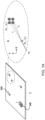
- stand-alone compact AE device 100 is provided to monitor the activity, location (xc, yc), size, and growth of cracks rc, in cover areas A of thin-walled structures 1.
- the device comprises a number of individual AE sensors 10-1..10-4, for example 4.
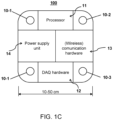
- the device comprises of a processor 11, a data acquisition unit 12, communication hardware 13 for data transfer, and power supply 14.
- the communication hardware 13 is provided with wireless communication capability.
- Advantageously sensors 10-1..10-4 are placed relatively close to each other, e.g.
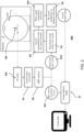
- Figure 2 shows in more detail a schematic flow chart of a data collection and processing system 200 wherein node may be incorporated 100, or may be communicatively coupled, for example, to a central data processing system 200, that may be wirelessly connected or connected via a physical network to a plurality of nodes.
- system 200 has processing circuitry to receive node data 100 that is substantially reduced (orders of magnitude) since, in this embodiment, (only) the result of the processed data from a node 100 comprising plurality of sensors 10-1..10-4 may be stored and transferred, instead of unprocessed data from each sensor.
- the computer implemented method executed by hardware run on this system is as follows. In a first step s1, the node 100 arrival times of an impinging wave is detected by sensors 10-1.. 10-4, as further illustrated in Figure 1c . In a second step s2, next, a specific beamforming analysis based on the guided waves characteristics is executed.
- Outputs of S2 are the identification of a dominant wave mode S22 and the finding S21 of a source of emission on a structure of interest 1, i.e. the AE source location of a detected crack r (xc, yc) by defining an error-minimization problem.
- a correction is carried out for dispersion of guided waves to reconstruct (step S41) an original ratio of wave modes at the source of emission.
- the original waveforms at the AE source are retrieved using a dispersion correction routine, which compensates for variation of the signal shape over the propagation distance, in this case from the crack location to the AE sensors.
- An example for dispersion correction of guided waves can be found in Sicard et. Al. (2002).
- the differential arrival times can be extracted from the dispersion corrected signals at this stage and replace the original values obtained from correlation of non-dispersion corrected signals. The updated differential arrival times can be used for improved location detection of the crack.
- step S41 i.e. an original ratio of wave modes originating from crack location r is correlated in a step S5 to a crack depth using a model, further exemplified in Figure 5 .
- Figure 3 shows a theoretical context of the detection of acoustic energy released due to crack growth. Growth of fatigue cracks in metals is associated with release of acoustic energy due to the breakage of the internal structure of the material being under excessive stress.
- the source and mechanism of this release of energy for a crack of certain depth and size are shown schematically in Figure 3A , with views A-A and B-B in cross and longitudinal direction of a crack r extending along direction B-B in a plate structure 300.
- the source of each AE signal is, in essence, a point on the leading edge of the crack, which can be used for depth estimation.
- the proposed AE solution extracts the information about the location of these sources in the plane of the thin-walled structure explicitly using a quasi-beamforming scheme, whereas the information about the AE source in the thickness-wise direction are obtained implicitly from the guided wave decomposition analysis.
- This analysis is based on the fact that the composition of the received signal in terms of S0 and A0 waves is a function of the source location in the thickness direction by dispersion effects.
- phase speed and group speed dispersion curves of phase speed and group speed for a medium are calculated to describe properties of the waves traveling within that medium.
- Phase speed and group speed dispersion curves respectively correlate the speed of each individual phase and an envelope of a wave mode to frequency.
- waves polarized in the vertical plane are described with the following transcendental equations [ Lamb, H. On Waves in an Elastic Plate. Proc. Roy. Soc. London, Ser.
- the dispersion curves for the fundamental modes S0 and A0 can be readily extracted from the equations above.
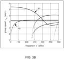
- An example of the group speed dispersion curve for construction steel can be seen in Figure 3B showing an graph illustrating group speeds for specified wave modes S0 and A0 in a steel plate of 12 mm thick.
- the group speed of the S0 wave, in a relevant frequency domain of for example 100-250 kHz is higher in the 150-200 kHz area typically 4-5 km/s and lower in the area above 200 kHz , where the A0 wave mode is typically around 3km/s.
- dispersion curves can be obtained from the guided (Lamb) wave theory, as discussed earlier.
- a generalized formulation can be used to obtain the dispersion curves for non-flat structures, e.g. storage tanks and pipes.
- FIG 4 shows a practical illustration how the wave mode analysis is carried out in sample waveforms obtained from experiments with the plate structure 300.
- traces 1-4 are shown, collected by corresponding AE sensors 10-1..4, e.g. upon crossing a predefined threshold criterion.
- an arrival of the faster S0 wave can be discerned about 600 ms, and later the slower A0 wave about 1000 ms, and time shifted and dispersed equivalents are detected in the other traces 2-4.
- ⁇ t ij arg max ⁇ ⁇ R ⁇ S ⁇ j t S ⁇ i t + ⁇ dt ⁇
- Band pass filtering in the example is performed in a range 100-250 kHz, blocking frequencies outside the range, for signals having frequency decompositions shown in Fig 4B showing maximum amplitudes for about 150 kHz (full width half maximum about 80 kHz).
- step S2 quasi-beamforming is carried out to identify as output a dominant wave S21 mode and calculated AE source location S22.
- This is achieved in accordance with the minimization problem mentioned earlier ( Fig 4C2 ): arg min x , y , c g F x c , y c , c g , ⁇ t ij , ⁇ i , j ⁇ 1 , 2 , ... , n , subject to : x y ⁇ ⁇ and c g ⁇ c S 0 ⁇ , c A 0 ⁇ where xc and yc denote the coordinates of an AE source in a plane of geometry (see for example, Figure 1 left), cg is the speed of the dominant wave mode, ⁇ (Omega) is the physical domain under inspection in the plane of geometry, cS0 and cA0 are the group speeds of the fundamental guided wave modes S0 and A0 as
- a dominant wave mode and corresponding speed is detected. Based on the identified dominant wave mode, which can be the faster S0 wave or the slower A0 wave, the other mode is also detected in the calculated time window corresponding to step S3 previously discussed in Figure 2 .
- the temporal position of this window is chosen equal to the distance of the AE sensors to the calculated crack location (xc,yc) divided by the group speed of the non-dominant wavemode given by the dispersion curve at the frequency of interest, measured from the time of the AE event, i.e. the distance from the AE sensors divided by the group speed of the dominant wave mode.
- an updated crack location can be estimated by further minimizing Equation (5) using the corrected arrival times corresponding to step S4 previously discussed in Figure 2 .
- a crack depth of the acoustic source origin can be calculated in an estimation using a characteristic curve correlating the crack depth to the ratio of S0 to A0 waves.
- the characteristic curve can be obtained from a forward analysis to express S0-to-A0 ratio as a function of the AE source depth (see Figure 3C).
- ⁇ (sigma), f, ⁇ (rho), u and ⁇ (Omega) denote the 3x3 stress tensor, external force vector, material density, displacement vector, and the physical domain of the structure respectively.
- Figure 5A shows schematically that depending on crack depth, a specific composition of A0 and S0 wave modes is released, which can be measured by measurement positions P1, P2.
- a correlation curve (see Figure 5B ) can for example be extracted using finite element analysis, known to the skilled person for a given structure.
- the structure that is shown is a flat plate, where boundary conditions apply as discussed in relation to Figure 3 and known to the skilled person. In this way, a footprint of the crack edges can be traced back and identified by the monitoring system during the crack growth process.
- the analysis distinguishes points P1 and P2 on opposite positions of the modeled structure, to identify the symmetric waves (S0,..) from anti-symmetric (A0, ..) ones and determine their ratio.
- different points P1 and P2 may be used, for example on a single face of the structure. Similar analysis can be performed for curved structures if the curvature is considered in the FEM model.
- Figure 5B illustrates a characteristic curve obtained by such analysis for a structural component of interest.
- a 2D plane-strain model of a waveguide was used with a notch being representative for a fatigue crack, as shown in Figure 5A .
- the notch is representative for a fatigue crack was constructed using higher-order finite element method (SEM).
- SEM finite element method
- ratio For deep cracks, i.e. having a crack depth approaching plate thickness, ratio will be similar to shallow cracks, thus introducing an ambiguity in the characteristic curve.
- a history bank is populated with crack depth history, so that for a designated crack, identified by a calculated location of the AE source, its deepness be resolved by matching a calculated ratio with a progress in time of the specific ratio, so that a crack depth can be derived from a position in progress on the characteristic curve.
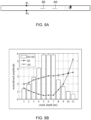
- Figure 6A and 6B give a further illustration of calculating a minimum error of an error function associated with an assumed combination of the source location, speed of a dominant wave mode, and identified arrival times of dominant and non-dominant wave modes.
- a number of cycles are from time traces of a randomly -chosen set of waveforms of around 100.000 cycles resulting in two localized cracks r1 having a depth of 2.9 and length of 32 mm and r2 having a depth of 1 mm and length of 27 mm respectively.
- the waveforms are recorded by the detectors located on a single device 100 having known relative detector positions, thereby finding a location of sources of acoustic emission on the structure of interest.
- the area rc indicates a minimum localization error, in a field test wherein the obtained speed from the QBF analysis yielded a wave speed of 3280 m/s of the A0 mode.
- a sensor arrangement is provided that is able to identify by placing a plurality of AE detectors on the structure of interest with relatively small distances from each other, whether on a square pattern, on a circular pattern, or with other relative locations.
Landscapes
- Physics & Mathematics (AREA)
- General Physics & Mathematics (AREA)
- Life Sciences & Earth Sciences (AREA)
- Pathology (AREA)
- Immunology (AREA)
- General Health & Medical Sciences (AREA)
- Biochemistry (AREA)
- Analytical Chemistry (AREA)
- Chemical & Material Sciences (AREA)
- Health & Medical Sciences (AREA)
- Mathematical Optimization (AREA)
- Signal Processing (AREA)
- Engineering & Computer Science (AREA)
- Pure & Applied Mathematics (AREA)
- Mathematical Physics (AREA)
- Mathematical Analysis (AREA)
- Algebra (AREA)
- Acoustics & Sound (AREA)
- Investigating Or Analyzing Materials By The Use Of Ultrasonic Waves (AREA)
Claims (6)
- Procédé de surveillance de fissures dans une structure d'intérêt en utilisant une détection d'émission acoustique (AE), comprenant les étapes consistant à :- placer une pluralité de détecteurs d'AE sur un dispositif unique sur la structure d'intérêt, présentant des positions de détecteur relatives connues ;- détecter pendant une fenêtre temporelle prédéfinie la puissance acoustique émise par une source d'AE dans des détecteurs sélectionnés en tant que traces temporelles (S1) ;- pour chaque ensemble de formes d'onde détectées au niveau des emplacements de détecteur, identifier un mode d'onde et une vitesse les plus plausibles dans une routine d'optimisation, en minimisant une fonction d'erreur (S2) associée à une combinaison supposée de l'emplacement de la source, de la vitesse d'un mode d'onde dominante et des temps d'arrivée identifiés d'un mode d'onde dominante avec une amplitude acoustique maximale au niveau des emplacements de détecteur, ce qui permet de trouver un emplacement d'une source d'émission acoustique sur la structure d'intérêt (S21) et un mode d'onde dominante (S22) ;- identifier, dans un intervalle de fréquence d'intérêt, une amplitude acoustique proche du maximum en tant que mode d'onde non dominante dans la fenêtre temporelle (S3) ;- mettre en corrélation un rapport des amplitudes de mode d'onde dominante et non dominante et une profondeur de fissure en utilisant une courbe caractéristique qui relie la profondeur de fissure à une amplitude et un rapport des compositions de mode d'onde (S5) ; et- remplir dans une banque d'archives des profondeurs de fissures mesurées pour des emplacements correspondants, de sorte que pour une fissure sélectionnée, identifiée par un emplacement calculé de la source d'AE, sa profondeur soit résolue en faisant correspondre un rapport calculé d'amplitudes de mode d'onde sur la courbe caractéristique- dans lequel les modes d'onde sont exprimés sous forme d'ondes de Lamb symétriques d'ordre zéro S0 et d'ondes de Lamb antisymétriques A0.
- Procédé selon la revendication 1, dans lequel la fenêtre de temps d'intérêt pour le mode d'onde non dominante est choisie sur la base d'un temps d'arrivée identifié du mode d'onde dominante ; d'une distance identifiée à partir de détecteurs sélectionnés jusqu'à un emplacement de fissure calculé (xc, yc) et d'une vitesse de groupe calculée des modes d'onde dominante et non dominante.
- Procédé selon la revendication 1, comprenant en outre les étapes consistant à :- corriger une dispersion sur la base d'un modèle de ladite structure pour reconstruire un rapport original des modes d'onde au niveau de la source d'émission (S4), et- mettre en corrélation le rapport original de modes d'onde à une profondeur de fissure.
- Procédé selon la revendication 1, dans lequel un critère de seuil commence la fenêtre temporelle pour détecter les traces temporelles.
- Procédé selon la revendication 1, dans lequel la fonction d'erreur est une fonction d'optimisation quadratique.
- Procédé selon la revendication 1, dans lequel la structure d'intérêt est métallique et à paroi mince.
Applications Claiming Priority (3)
| Application Number | Priority Date | Filing Date | Title |
|---|---|---|---|
| EP14153948 | 2014-02-05 | ||
| EP14168054 | 2014-05-13 | ||
| PCT/NL2015/050075 WO2015119498A1 (fr) | 2014-02-05 | 2015-02-04 | Système et procédé de surveillance de fissures |
Publications (2)
| Publication Number | Publication Date |
|---|---|
| EP3102932A1 EP3102932A1 (fr) | 2016-12-14 |
| EP3102932B1 true EP3102932B1 (fr) | 2025-04-02 |
Family
ID=52474055
Family Applications (1)
| Application Number | Title | Priority Date | Filing Date |
|---|---|---|---|
| EP15704861.2A Active EP3102932B1 (fr) | 2014-02-05 | 2015-02-04 | Procédé de surveillance de fissures |
Country Status (3)
| Country | Link |
|---|---|
| US (1) | US10175205B2 (fr) |
| EP (1) | EP3102932B1 (fr) |
| WO (1) | WO2015119498A1 (fr) |
Cited By (1)
| Publication number | Priority date | Publication date | Assignee | Title |
|---|---|---|---|---|
| US20220412926A1 (en) * | 2021-05-12 | 2022-12-29 | University Of South Carolina | Ai method and apparatus for extracting crack length from high-frequency ae (acoustic emission) |
Families Citing this family (11)
| Publication number | Priority date | Publication date | Assignee | Title |
|---|---|---|---|---|
| WO2017149658A1 (fr) * | 2016-03-01 | 2017-09-08 | 三菱電機株式会社 | Dispositif de mesure par ultrasons et procédé de mesure par ultrasons |
| FR3060743B1 (fr) * | 2016-12-15 | 2019-05-17 | Commissariat A L'energie Atomique Et Aux Energies Alternatives | Procede et systeme de controle de sante integre d'une structure mecanique par ondes elastiques diffuses |
| JP2018155662A (ja) * | 2017-03-17 | 2018-10-04 | 株式会社東芝 | 位置標定システム、位置標定方法及びコンピュータプログラム |
| WO2019069707A1 (fr) * | 2017-10-05 | 2019-04-11 | ソニーセミコンダクタソリューションズ株式会社 | Dispositif de détection de potentiel électrique de cellule, procédé de fabrication de dispositif de détection de potentiel électrique de cellule et système de traitement d'informations |
| CN108037185A (zh) * | 2017-11-25 | 2018-05-15 | 中国科学院金属研究所 | 一种基于声发射技术的碳化硅纤维增强钛基复合材料纤维断裂检测方法 |
| CN108519596A (zh) * | 2018-03-05 | 2018-09-11 | 长沙理工大学 | 一种基于匹配追踪和小波变换的管片隐伏裂缝识别方法 |
| CN110687197B (zh) * | 2019-08-26 | 2021-12-24 | 天津大学 | 一种自适应航天器碎片碰撞的定位方法 |
| CN111812211B (zh) * | 2020-07-09 | 2021-09-24 | 武汉理工大学 | 一种基于声发射参数的ra–af–e岩石类材料脆性破坏裂纹分类方法 |
| JP7614768B2 (ja) | 2020-09-16 | 2025-01-16 | 株式会社東芝 | 測定装置及び測定方法 |
| CN112683930B (zh) * | 2020-12-11 | 2022-07-29 | 广东工业大学 | 一种用于金属裂纹的检测装置和方法 |
| JP7763729B2 (ja) * | 2022-08-04 | 2025-11-04 | 東京瓦斯株式会社 | 管状構造物の腐食およびき裂検知方法 |
Family Cites Families (27)
| Publication number | Priority date | Publication date | Assignee | Title |
|---|---|---|---|---|
| US3713127A (en) | 1970-10-16 | 1973-01-23 | Trodyne Corp | Acoustic emission crack monitor |
| US4435984A (en) | 1980-04-21 | 1984-03-13 | Southwest Research Institute | Ultrasonic multiple-beam technique for detecting cracks in bimetallic or coarse-grained materials |
| US5014556A (en) * | 1990-01-16 | 1991-05-14 | Dunegan Engineering Consultants, Inc. | Acoustic emission simulator |
| WO1996022527A1 (fr) | 1995-01-17 | 1996-07-25 | The Penn State Research Foundation | Endoscope pour inspection de tube a l'aide d'ondes guidees et procede associe |
| US5635643A (en) * | 1995-03-15 | 1997-06-03 | The University Of New Mexico | Identifying source of acoustic emissions in structures using lamb waves and vibration modes |
| US5714687A (en) | 1995-10-31 | 1998-02-03 | Dunegan; Harold L. | Transducer for measuring acoustic emission events |
| US6173613B1 (en) * | 1996-04-30 | 2001-01-16 | Harold L. Dunegan | Measuring crack growth by acoustic emission |
| WO2001050122A1 (fr) | 2000-01-03 | 2001-07-12 | The Board Of Regents Of The University Of Nebraska | Procede et systeme hybride transitoire-parametrique destines a distinguer et analyser des sources d'emission acoustique dans un but d'inspection non destructive et de controle d'etat de structures |
| US6751560B1 (en) | 2000-08-01 | 2004-06-15 | The Charles Stark Draper Laboratory, Inc. | Non-invasive pipeline inspection system |
| US6634236B2 (en) | 2000-08-31 | 2003-10-21 | Cooper Technology Services, Llc | Method and article of manufacture for estimating material failure due to crack formation and growth |
| WO2002062206A2 (fr) | 2001-02-08 | 2002-08-15 | University Of South Carolina | Systeme structurel de diagnostic, de pronostic, de monitorage de la sante in situ faisant appel a de minces capteurs piezo-electriques |
| US20030167141A1 (en) | 2001-12-20 | 2003-09-04 | Staszewski Wieslaw J. | Structural health monitoring |
| WO2003106958A2 (fr) | 2002-06-14 | 2003-12-24 | University Of South Carolina | Systeme de surveillance de l'etat d'une structure faisant appel a un radar de structure integre ultrasonique a ondes de lamb guidees |
| GB2416207B (en) * | 2004-07-15 | 2008-08-27 | Ultra Electronics Ltd | Acoustic structural integrity monitoring system and method |
| US7565252B2 (en) | 2005-12-06 | 2009-07-21 | Southwest Research Institute | Method for automatic differentiation of weld signals from defect signals in long-range guided-wave inspection using phase comparison |
| US20090048789A1 (en) | 2007-04-13 | 2009-02-19 | University Of South Carolina | Optimized Embedded Ultrasonics Structural Radar System With Piezoelectric Wafer Active Sensor Phased Arrays For In-Situ Wide-Area Damage Detection |
| US8170809B2 (en) | 2007-11-14 | 2012-05-01 | Fbs, Inc. | Guided waves for nondestructive testing of pipes |
| US7997139B2 (en) | 2007-12-03 | 2011-08-16 | Fbs, Inc. | Guided wave pipeline inspection system and method with enhanced natural focusing techniques |
| EP2232123B1 (fr) | 2008-01-11 | 2014-09-17 | PII Limited | Appareil et procédé d'inspection de pipelines utilisant deux modes d'oscillation ultrasoniques différents |
| US7881881B2 (en) | 2008-08-12 | 2011-02-01 | University Of South Carolina | Structural health monitoring apparatus and methodology |
| US8532940B2 (en) | 2009-02-18 | 2013-09-10 | Fbs, Inc. | Systems and methods for the inspection of structures having unknown properties |
| US8285495B2 (en) | 2009-04-29 | 2012-10-09 | Techno-Sciences, Inc | Corrosion inspection and monitoring system |
| GB2482124B (en) * | 2010-07-19 | 2016-08-17 | Ultra Electronics Ltd | Acoustic structural integrity monitoring system and method |
| US8316712B2 (en) | 2010-11-19 | 2012-11-27 | Margan Physical Diagnostics Ltd. | Quantitative acoustic emission non-destructive inspection for revealing, typifying and assessing fracture hazards |
| US9581570B2 (en) | 2011-02-10 | 2017-02-28 | University Of South Carolina | Determination of the remaining life of a structural system based on acoustic emission signals |
| WO2012172124A1 (fr) | 2011-06-15 | 2012-12-20 | Aernnova Engineering Solutions Iberica | Architecture électronique multicanal pour surveillance avancée de l'intégrité structurale par la technique des ondes ultrasonores guidées ou ondes de lamb |
| US9213019B2 (en) | 2011-11-18 | 2015-12-15 | General Electric Company | Method of determining a size of a defect using an ultrasonic linear phased array |
-
2015
- 2015-02-04 WO PCT/NL2015/050075 patent/WO2015119498A1/fr not_active Ceased
- 2015-02-04 US US15/115,826 patent/US10175205B2/en active Active
- 2015-02-04 EP EP15704861.2A patent/EP3102932B1/fr active Active
Cited By (1)
| Publication number | Priority date | Publication date | Assignee | Title |
|---|---|---|---|---|
| US20220412926A1 (en) * | 2021-05-12 | 2022-12-29 | University Of South Carolina | Ai method and apparatus for extracting crack length from high-frequency ae (acoustic emission) |
Also Published As
| Publication number | Publication date |
|---|---|
| US10175205B2 (en) | 2019-01-08 |
| WO2015119498A1 (fr) | 2015-08-13 |
| US20170074832A1 (en) | 2017-03-16 |
| EP3102932A1 (fr) | 2016-12-14 |
Similar Documents
| Publication | Publication Date | Title |
|---|---|---|
| EP3102932B1 (fr) | Procédé de surveillance de fissures | |
| Al-Jumaili et al. | Acoustic emission source location in complex structures using full automatic delta T mapping technique | |
| US9513372B2 (en) | Automatic processing of ultrasonic data | |
| Perelli et al. | Acoustic emission localization in plates with dispersion and reverberations using sparse PZT sensors in passive mode | |
| US20200191754A1 (en) | Detection, monitoring, and determination of location of changes in metallic structures using multimode acoustic signals | |
| Grabowski et al. | Time–distance domain transformation for Acoustic Emission source localization in thin metallic plates | |
| US20170191966A1 (en) | Distributed circle method for guided wave based corrosion detection in plate-like structures | |
| Niri et al. | Determination of the probability zone for acoustic emission source location in cylindrical shell structures | |
| Haynes et al. | Enhanced damage localization for complex structures through statistical modeling and sensor fusion | |
| BR102015021137A2 (pt) | avaliação de impacto de pesquisas sísmicas marinhas | |
| US9001614B1 (en) | System for self-localizing near field data processing | |
| Jarvis et al. | Performance evaluation of a magnetic field measurement NDE technique using a model assisted Probability of Detection framework | |
| KR100937095B1 (ko) | 유도초음파를 이용한 구조건전성 모니터링 방법 | |
| Zhang et al. | Defect localization in plate structures using the geometric phase of Lamb waves | |
| KR20100090912A (ko) | 유도초음파를 이용한 구조건전성 모니터링 방법 | |
| Yan | A particle filter method for damage location in plate‐like structures by using Lamb waves | |
| Fromme | Monitoring of plate structures using guided ultrasonic waves | |
| Hong et al. | Reverse engineering stiffened plates using guided wave-based nondestructive testing methods | |
| Zhou et al. | A rapid localization technique for detecting multiple damages in plate-like structures with unknown material properties | |
| CN105046859B (zh) | 基于振动信号空时二维稀疏表示k‑s检验的光纤入侵检测方法 | |
| Ling et al. | LSDC-RC-RAPID: An improved probabilistic reconstruction approach for pipeline corrosion detection with UGWT | |
| US20150106037A1 (en) | Method and system for passive detection, localization and characterization of mechanical wave sources using ultrasonic guided waves | |
| Zhang et al. | The efficiency of arrival time picking methods for acoustic emission source localization in structures with simultaneous damage mechanisms | |
| Cegla et al. | Mitigating the effects of surface morphology changes during ultrasonic wall thickness monitoring | |
| RU2463631C1 (ru) | Способ обнаружения очагов землетрясений сетью сейсмостанций |
Legal Events
| Date | Code | Title | Description |
|---|---|---|---|
| PUAI | Public reference made under article 153(3) epc to a published international application that has entered the european phase |
Free format text: ORIGINAL CODE: 0009012 |
|
| STAA | Information on the status of an ep patent application or granted ep patent |
Free format text: STATUS: REQUEST FOR EXAMINATION WAS MADE |
|
| 17P | Request for examination filed |
Effective date: 20160811 |
|
| AK | Designated contracting states |
Kind code of ref document: A1 Designated state(s): AL AT BE BG CH CY CZ DE DK EE ES FI FR GB GR HR HU IE IS IT LI LT LU LV MC MK MT NL NO PL PT RO RS SE SI SK SM TR |
|
| AX | Request for extension of the european patent |
Extension state: BA ME |
|
| DAX | Request for extension of the european patent (deleted) | ||
| STAA | Information on the status of an ep patent application or granted ep patent |
Free format text: STATUS: EXAMINATION IS IN PROGRESS |
|
| 17Q | First examination report despatched |
Effective date: 20190718 |
|
| P01 | Opt-out of the competence of the unified patent court (upc) registered |
Effective date: 20230522 |
|
| GRAP | Despatch of communication of intention to grant a patent |
Free format text: ORIGINAL CODE: EPIDOSNIGR1 |
|
| STAA | Information on the status of an ep patent application or granted ep patent |
Free format text: STATUS: GRANT OF PATENT IS INTENDED |
|
| INTG | Intention to grant announced |
Effective date: 20241017 |
|
| GRAS | Grant fee paid |
Free format text: ORIGINAL CODE: EPIDOSNIGR3 |
|
| GRAA | (expected) grant |
Free format text: ORIGINAL CODE: 0009210 |
|
| STAA | Information on the status of an ep patent application or granted ep patent |
Free format text: STATUS: THE PATENT HAS BEEN GRANTED |
|
| AK | Designated contracting states |
Kind code of ref document: B1 Designated state(s): AL AT BE BG CH CY CZ DE DK EE ES FI FR GB GR HR HU IE IS IT LI LT LU LV MC MK MT NL NO PL PT RO RS SE SI SK SM TR |
|
| REG | Reference to a national code |
Ref country code: GB Ref legal event code: FG4D |
|
| REG | Reference to a national code |
Ref country code: CH Ref legal event code: EP |
|
| REG | Reference to a national code |
Ref country code: IE Ref legal event code: FG4D |
|
| REG | Reference to a national code |
Ref country code: DE Ref legal event code: R096 Ref document number: 602015091333 Country of ref document: DE |
|
| REG | Reference to a national code |
Ref country code: NL Ref legal event code: FP |
|
| REG | Reference to a national code |
Ref country code: AT Ref legal event code: MK05 Ref document number: 1781731 Country of ref document: AT Kind code of ref document: T Effective date: 20250402 |
|
| PG25 | Lapsed in a contracting state [announced via postgrant information from national office to epo] |
Ref country code: ES Free format text: LAPSE BECAUSE OF FAILURE TO SUBMIT A TRANSLATION OF THE DESCRIPTION OR TO PAY THE FEE WITHIN THE PRESCRIBED TIME-LIMIT Effective date: 20250402 Ref country code: PT Free format text: LAPSE BECAUSE OF FAILURE TO SUBMIT A TRANSLATION OF THE DESCRIPTION OR TO PAY THE FEE WITHIN THE PRESCRIBED TIME-LIMIT Effective date: 20250804 Ref country code: FI Free format text: LAPSE BECAUSE OF FAILURE TO SUBMIT A TRANSLATION OF THE DESCRIPTION OR TO PAY THE FEE WITHIN THE PRESCRIBED TIME-LIMIT Effective date: 20250402 |
|
| REG | Reference to a national code |
Ref country code: LT Ref legal event code: MG9D |
|
| PG25 | Lapsed in a contracting state [announced via postgrant information from national office to epo] |
Ref country code: GR Free format text: LAPSE BECAUSE OF FAILURE TO SUBMIT A TRANSLATION OF THE DESCRIPTION OR TO PAY THE FEE WITHIN THE PRESCRIBED TIME-LIMIT Effective date: 20250703 Ref country code: NO Free format text: LAPSE BECAUSE OF FAILURE TO SUBMIT A TRANSLATION OF THE DESCRIPTION OR TO PAY THE FEE WITHIN THE PRESCRIBED TIME-LIMIT Effective date: 20250702 |
|
| PG25 | Lapsed in a contracting state [announced via postgrant information from national office to epo] |
Ref country code: PL Free format text: LAPSE BECAUSE OF FAILURE TO SUBMIT A TRANSLATION OF THE DESCRIPTION OR TO PAY THE FEE WITHIN THE PRESCRIBED TIME-LIMIT Effective date: 20250402 |
|
| PG25 | Lapsed in a contracting state [announced via postgrant information from national office to epo] |
Ref country code: BG Free format text: LAPSE BECAUSE OF FAILURE TO SUBMIT A TRANSLATION OF THE DESCRIPTION OR TO PAY THE FEE WITHIN THE PRESCRIBED TIME-LIMIT Effective date: 20250402 |
|
| PG25 | Lapsed in a contracting state [announced via postgrant information from national office to epo] |
Ref country code: HR Free format text: LAPSE BECAUSE OF FAILURE TO SUBMIT A TRANSLATION OF THE DESCRIPTION OR TO PAY THE FEE WITHIN THE PRESCRIBED TIME-LIMIT Effective date: 20250402 |
|
| PG25 | Lapsed in a contracting state [announced via postgrant information from national office to epo] |
Ref country code: AT Free format text: LAPSE BECAUSE OF FAILURE TO SUBMIT A TRANSLATION OF THE DESCRIPTION OR TO PAY THE FEE WITHIN THE PRESCRIBED TIME-LIMIT Effective date: 20250402 |
|
| PG25 | Lapsed in a contracting state [announced via postgrant information from national office to epo] |
Ref country code: RS Free format text: LAPSE BECAUSE OF FAILURE TO SUBMIT A TRANSLATION OF THE DESCRIPTION OR TO PAY THE FEE WITHIN THE PRESCRIBED TIME-LIMIT Effective date: 20250702 |
|
| PG25 | Lapsed in a contracting state [announced via postgrant information from national office to epo] |
Ref country code: IS Free format text: LAPSE BECAUSE OF FAILURE TO SUBMIT A TRANSLATION OF THE DESCRIPTION OR TO PAY THE FEE WITHIN THE PRESCRIBED TIME-LIMIT Effective date: 20250802 |
|
| PG25 | Lapsed in a contracting state [announced via postgrant information from national office to epo] |
Ref country code: LV Free format text: LAPSE BECAUSE OF FAILURE TO SUBMIT A TRANSLATION OF THE DESCRIPTION OR TO PAY THE FEE WITHIN THE PRESCRIBED TIME-LIMIT Effective date: 20250402 |
|
| REG | Reference to a national code |
Ref country code: DE Ref legal event code: R097 Ref document number: 602015091333 Country of ref document: DE |
|
| PG25 | Lapsed in a contracting state [announced via postgrant information from national office to epo] |
Ref country code: DK Free format text: LAPSE BECAUSE OF FAILURE TO SUBMIT A TRANSLATION OF THE DESCRIPTION OR TO PAY THE FEE WITHIN THE PRESCRIBED TIME-LIMIT Effective date: 20250402 Ref country code: SM Free format text: LAPSE BECAUSE OF FAILURE TO SUBMIT A TRANSLATION OF THE DESCRIPTION OR TO PAY THE FEE WITHIN THE PRESCRIBED TIME-LIMIT Effective date: 20250402 |
|
| PG25 | Lapsed in a contracting state [announced via postgrant information from national office to epo] |
Ref country code: CZ Free format text: LAPSE BECAUSE OF FAILURE TO SUBMIT A TRANSLATION OF THE DESCRIPTION OR TO PAY THE FEE WITHIN THE PRESCRIBED TIME-LIMIT Effective date: 20250402 |
|
| PG25 | Lapsed in a contracting state [announced via postgrant information from national office to epo] |
Ref country code: EE Free format text: LAPSE BECAUSE OF FAILURE TO SUBMIT A TRANSLATION OF THE DESCRIPTION OR TO PAY THE FEE WITHIN THE PRESCRIBED TIME-LIMIT Effective date: 20250402 |
|
| PG25 | Lapsed in a contracting state [announced via postgrant information from national office to epo] |
Ref country code: SK Free format text: LAPSE BECAUSE OF FAILURE TO SUBMIT A TRANSLATION OF THE DESCRIPTION OR TO PAY THE FEE WITHIN THE PRESCRIBED TIME-LIMIT Effective date: 20250402 Ref country code: RO Free format text: LAPSE BECAUSE OF FAILURE TO SUBMIT A TRANSLATION OF THE DESCRIPTION OR TO PAY THE FEE WITHIN THE PRESCRIBED TIME-LIMIT Effective date: 20250402 |
|
| PG25 | Lapsed in a contracting state [announced via postgrant information from national office to epo] |
Ref country code: IT Free format text: LAPSE BECAUSE OF FAILURE TO SUBMIT A TRANSLATION OF THE DESCRIPTION OR TO PAY THE FEE WITHIN THE PRESCRIBED TIME-LIMIT Effective date: 20250402 |
|
| PLBE | No opposition filed within time limit |
Free format text: ORIGINAL CODE: 0009261 |
|
| STAA | Information on the status of an ep patent application or granted ep patent |
Free format text: STATUS: NO OPPOSITION FILED WITHIN TIME LIMIT |
|
| REG | Reference to a national code |
Ref country code: CH Ref legal event code: L10 Free format text: ST27 STATUS EVENT CODE: U-0-0-L10-L00 (AS PROVIDED BY THE NATIONAL OFFICE) Effective date: 20260211 |
|
| 26N | No opposition filed |
Effective date: 20260105 |
|
| PGFP | Annual fee paid to national office [announced via postgrant information from national office to epo] |
Ref country code: NL Payment date: 20260218 Year of fee payment: 12 |
|
| PGFP | Annual fee paid to national office [announced via postgrant information from national office to epo] |
Ref country code: GB Payment date: 20260219 Year of fee payment: 12 |
|
| PGFP | Annual fee paid to national office [announced via postgrant information from national office to epo] |
Ref country code: DE Payment date: 20260218 Year of fee payment: 12 |
|
| PGFP | Annual fee paid to national office [announced via postgrant information from national office to epo] |
Ref country code: FR Payment date: 20260218 Year of fee payment: 12 |