EP3103061B1 - Procédé et appareil permettant de générer et stocker un profil d'imperfection individuel lié à un article original ainsi que procédé et appareil permettant de déterminer un état d'authentification d'un article suspect - Google Patents
Procédé et appareil permettant de générer et stocker un profil d'imperfection individuel lié à un article original ainsi que procédé et appareil permettant de déterminer un état d'authentification d'un article suspect Download PDFInfo
- Publication number
- EP3103061B1 EP3103061B1 EP15703926.4A EP15703926A EP3103061B1 EP 3103061 B1 EP3103061 B1 EP 3103061B1 EP 15703926 A EP15703926 A EP 15703926A EP 3103061 B1 EP3103061 B1 EP 3103061B1
- Authority
- EP
- European Patent Office
- Prior art keywords
- item
- picture
- code
- module
- printed
- Prior art date
- Legal status (The legal status is an assumption and is not a legal conclusion. Google has not performed a legal analysis and makes no representation as to the accuracy of the status listed.)
- Active
Links
Images









Classifications
-
- G—PHYSICS
- G06—COMPUTING OR CALCULATING; COUNTING
- G06K—GRAPHICAL DATA READING; PRESENTATION OF DATA; RECORD CARRIERS; HANDLING RECORD CARRIERS
- G06K19/00—Record carriers for use with machines and with at least a part designed to carry digital markings
- G06K19/06—Record carriers for use with machines and with at least a part designed to carry digital markings characterised by the kind of the digital marking, e.g. shape, nature, code
- G06K19/08—Record carriers for use with machines and with at least a part designed to carry digital markings characterised by the kind of the digital marking, e.g. shape, nature, code using markings of different kinds or more than one marking of the same kind in the same record carrier, e.g. one marking being sensed by optical and the other by magnetic means
- G06K19/10—Record carriers for use with machines and with at least a part designed to carry digital markings characterised by the kind of the digital marking, e.g. shape, nature, code using markings of different kinds or more than one marking of the same kind in the same record carrier, e.g. one marking being sensed by optical and the other by magnetic means at least one kind of marking being used for authentication, e.g. of credit or identity cards
-
- G—PHYSICS
- G06—COMPUTING OR CALCULATING; COUNTING
- G06V—IMAGE OR VIDEO RECOGNITION OR UNDERSTANDING
- G06V20/00—Scenes; Scene-specific elements
- G06V20/80—Recognising image objects characterised by unique random patterns
-
- G—PHYSICS
- G06—COMPUTING OR CALCULATING; COUNTING
- G06F—ELECTRIC DIGITAL DATA PROCESSING
- G06F16/00—Information retrieval; Database structures therefor; File system structures therefor
- G06F16/50—Information retrieval; Database structures therefor; File system structures therefor of still image data
- G06F16/58—Retrieval characterised by using metadata, e.g. metadata not derived from the content or metadata generated manually
- G06F16/5866—Retrieval characterised by using metadata, e.g. metadata not derived from the content or metadata generated manually using information manually generated, e.g. tags, keywords, comments, manually generated location and time information
-
- G—PHYSICS
- G06—COMPUTING OR CALCULATING; COUNTING
- G06K—GRAPHICAL DATA READING; PRESENTATION OF DATA; RECORD CARRIERS; HANDLING RECORD CARRIERS
- G06K19/00—Record carriers for use with machines and with at least a part designed to carry digital markings
- G06K19/06—Record carriers for use with machines and with at least a part designed to carry digital markings characterised by the kind of the digital marking, e.g. shape, nature, code
- G06K19/06009—Record carriers for use with machines and with at least a part designed to carry digital markings characterised by the kind of the digital marking, e.g. shape, nature, code with optically detectable marking
- G06K19/06037—Record carriers for use with machines and with at least a part designed to carry digital markings characterised by the kind of the digital marking, e.g. shape, nature, code with optically detectable marking multi-dimensional coding
-
- G—PHYSICS
- G06—COMPUTING OR CALCULATING; COUNTING
- G06K—GRAPHICAL DATA READING; PRESENTATION OF DATA; RECORD CARRIERS; HANDLING RECORD CARRIERS
- G06K7/00—Methods or arrangements for sensing record carriers, e.g. for reading patterns
- G06K7/10—Methods or arrangements for sensing record carriers, e.g. for reading patterns by electromagnetic radiation, e.g. optical sensing; by corpuscular radiation
- G06K7/10544—Methods or arrangements for sensing record carriers, e.g. for reading patterns by electromagnetic radiation, e.g. optical sensing; by corpuscular radiation by scanning of the records by radiation in the optical part of the electromagnetic spectrum
- G06K7/10712—Fixed beam scanning
- G06K7/10722—Photodetector array or CCD scanning
- G06K7/10732—Light sources
-
- G—PHYSICS
- G06—COMPUTING OR CALCULATING; COUNTING
- G06K—GRAPHICAL DATA READING; PRESENTATION OF DATA; RECORD CARRIERS; HANDLING RECORD CARRIERS
- G06K7/00—Methods or arrangements for sensing record carriers, e.g. for reading patterns
- G06K7/10—Methods or arrangements for sensing record carriers, e.g. for reading patterns by electromagnetic radiation, e.g. optical sensing; by corpuscular radiation
- G06K7/14—Methods or arrangements for sensing record carriers, e.g. for reading patterns by electromagnetic radiation, e.g. optical sensing; by corpuscular radiation using light without selection of wavelength, e.g. sensing reflected white light
- G06K7/1404—Methods for optical code recognition
- G06K7/1408—Methods for optical code recognition the method being specifically adapted for the type of code
- G06K7/1417—2D bar codes
-
- G—PHYSICS
- G06—COMPUTING OR CALCULATING; COUNTING
- G06K—GRAPHICAL DATA READING; PRESENTATION OF DATA; RECORD CARRIERS; HANDLING RECORD CARRIERS
- G06K7/00—Methods or arrangements for sensing record carriers, e.g. for reading patterns
- G06K7/10—Methods or arrangements for sensing record carriers, e.g. for reading patterns by electromagnetic radiation, e.g. optical sensing; by corpuscular radiation
- G06K7/14—Methods or arrangements for sensing record carriers, e.g. for reading patterns by electromagnetic radiation, e.g. optical sensing; by corpuscular radiation using light without selection of wavelength, e.g. sensing reflected white light
- G06K7/1404—Methods for optical code recognition
- G06K7/1439—Methods for optical code recognition including a method step for retrieval of the optical code
- G06K7/1443—Methods for optical code recognition including a method step for retrieval of the optical code locating of the code in an image
-
- G—PHYSICS
- G06—COMPUTING OR CALCULATING; COUNTING
- G06K—GRAPHICAL DATA READING; PRESENTATION OF DATA; RECORD CARRIERS; HANDLING RECORD CARRIERS
- G06K7/00—Methods or arrangements for sensing record carriers, e.g. for reading patterns
- G06K7/10—Methods or arrangements for sensing record carriers, e.g. for reading patterns by electromagnetic radiation, e.g. optical sensing; by corpuscular radiation
- G06K7/14—Methods or arrangements for sensing record carriers, e.g. for reading patterns by electromagnetic radiation, e.g. optical sensing; by corpuscular radiation using light without selection of wavelength, e.g. sensing reflected white light
- G06K7/1404—Methods for optical code recognition
- G06K7/1439—Methods for optical code recognition including a method step for retrieval of the optical code
- G06K7/1452—Methods for optical code recognition including a method step for retrieval of the optical code detecting bar code edges
-
- G—PHYSICS
- G06—COMPUTING OR CALCULATING; COUNTING
- G06K—GRAPHICAL DATA READING; PRESENTATION OF DATA; RECORD CARRIERS; HANDLING RECORD CARRIERS
- G06K7/00—Methods or arrangements for sensing record carriers, e.g. for reading patterns
- G06K7/10—Methods or arrangements for sensing record carriers, e.g. for reading patterns by electromagnetic radiation, e.g. optical sensing; by corpuscular radiation
- G06K7/14—Methods or arrangements for sensing record carriers, e.g. for reading patterns by electromagnetic radiation, e.g. optical sensing; by corpuscular radiation using light without selection of wavelength, e.g. sensing reflected white light
- G06K7/1404—Methods for optical code recognition
- G06K7/1439—Methods for optical code recognition including a method step for retrieval of the optical code
- G06K7/1456—Methods for optical code recognition including a method step for retrieval of the optical code determining the orientation of the optical code with respect to the reader and correcting therefore
-
- G—PHYSICS
- G06—COMPUTING OR CALCULATING; COUNTING
- G06K—GRAPHICAL DATA READING; PRESENTATION OF DATA; RECORD CARRIERS; HANDLING RECORD CARRIERS
- G06K7/00—Methods or arrangements for sensing record carriers, e.g. for reading patterns
- G06K7/10—Methods or arrangements for sensing record carriers, e.g. for reading patterns by electromagnetic radiation, e.g. optical sensing; by corpuscular radiation
- G06K7/14—Methods or arrangements for sensing record carriers, e.g. for reading patterns by electromagnetic radiation, e.g. optical sensing; by corpuscular radiation using light without selection of wavelength, e.g. sensing reflected white light
- G06K7/1404—Methods for optical code recognition
- G06K7/146—Methods for optical code recognition the method including quality enhancement steps
- G06K7/1473—Methods for optical code recognition the method including quality enhancement steps error correction
-
- G—PHYSICS
- G06—COMPUTING OR CALCULATING; COUNTING
- G06Q—INFORMATION AND COMMUNICATION TECHNOLOGY [ICT] SPECIALLY ADAPTED FOR ADMINISTRATIVE, COMMERCIAL, FINANCIAL, MANAGERIAL OR SUPERVISORY PURPOSES; SYSTEMS OR METHODS SPECIALLY ADAPTED FOR ADMINISTRATIVE, COMMERCIAL, FINANCIAL, MANAGERIAL OR SUPERVISORY PURPOSES, NOT OTHERWISE PROVIDED FOR
- G06Q30/00—Commerce
- G06Q30/018—Certifying business or products
-
- G—PHYSICS
- G06—COMPUTING OR CALCULATING; COUNTING
- G06V—IMAGE OR VIDEO RECOGNITION OR UNDERSTANDING
- G06V20/00—Scenes; Scene-specific elements
- G06V20/95—Pattern authentication; Markers therefor; Forgery detection
Definitions
- the present invention relates to a method and apparatus for generating and storing an individual imperfection profile related to an original item as well as to a hereto related method and apparatus for determining an authentication status of a suspect item, and use of the authentication apparatus.
- the invention further relates to a computer program for performing the mentioned methods as well as to a data carrier having a data structure stored thereon, which, after loading into a computer or a computer network, is capable of executing the methods.
- a substrate such as a paper or a cardboard
- organic and anisotropic material structure due to its organic and anisotropic material structure, generally absorbs inks locally in an individual manner, by which process non-reproducible patterns may evolve throughout the area wherein the ink is absorbed, particularly at the margins of such areas.
- US 5,521,984 A discloses a method for determining an authentication status of a suspect item particularly applicable to objects of fine art, including limited edition prints, and which is based on the uniqueness of actions involved in the creation of such an object, e.g. a brush stroke exerted by an artist.
- the authentication of the original item is determined by recording at a microscopic level a unique pattern of such a feature at a selected microsite of the original item which is subsequently stored in a central data storage from which it can be retrieved over a communication link upon request and compared with an actually recorded picture of the same microsite of the suspect item.
- a further example may be found in WO 2013/130946 A1 , wherein natural variations in marked features on an item, such as a barcode oriented onto the item, are assessed with respect to artifacts which are specific to the item.
- information associated with the artifacts is extracted, whereupon the information is ranked according to characteristics of the artifacts, in particular by calculating an autocorrelation series of the ranked information.
- ranking includes treating artifacts with a characteristic below a threshold differently from artifacts above the threshold, such as not ranking artifacts smaller than the threshold, or grouping artifacts together with locations where no artifact is detected, or discounting artifacts.
- the ranked information or data representing the autocorrelation series are stored in a storage device separate from the original item.
- the modules of a two-dimensional barcode such as a data matrix barcode
- an optical system which comprises a resolution of 5 pixels per dimension.
- 40 pixels per dimension are needed.
- this requirement which increases the resolution of the optical system by a factor of 8 in each dimension leads to an increase of the data volume to be further processed by a factor of 64. Consequently, the requirements on the optical system as well as on the data storage system are multiplied in a system which is configured for assessing margins of a print image compared to a device being adapted for simply decoding a two-dimensional barcode.
- Orban Bulan, High Capacity Color Barcodes Per Channel Data Encoding via Orientation Modulation in Elliptical Dot Arrays, IEEE Transactions On Image Processing, Vol. 20, No. 5, May 2011, pages 1337-1350 , discloses a new high capacity color barcode which uses the cyan, magenta, and yellow (C,M,Y) colorant separations available in color printers and enables high capacity by independently encoding data in each of these separations.
- payload data is conveyed by using a periodic array of elliptically shaped dots whose individual orientations are modulated to encode the data.
- the orientation based data encoding provides beneficial robustness against printer and scanner tone variations.
- the overall color barcode is obtained when these color separations are printed in overlay as in common color printing.
- a reader recovers the barcode data from a conventional color scan of the barcode, using red, green, and blue (R,G,B) channels complementary, respectively, to the print C, M, and Y channels.
- R,G,B red, green, and blue
- For each channel first the periodic arrangement of dots is exploited at the reader to enable synchronization by compensating for both global rotation/scaling in scanning and local distortion in printing.
- An error correction methodology that effectively utilizes the channel model is employed.
- optical systems particularly within the pharmaceutical industry, where barcodes are printed onto the items for serializing single products.
- existing recording devices which could be already adapted for recording print images with speeds and typically low resolutions, such as approx. 5 pixels per module, as generally employed within industrial facilities.
- Such facilities are designed to record up to 2,000 or more pictures per minute, which would mean that the present method should be able to be performed at a speed much faster than any other known authentication method.
- This problem is solved by a method and an apparatus for generating and storing an individual imperfection profile related to an original item, as defined in independent claims 1 and 10, respectively.
- This problem is further solved by a hereto related method, apparatus and use of the apparatus for determining an authentication status of a suspect item, as defined in claims 6, 11 and 13, respectively.
- the problem is further solved by a computer program for performing any of the methods according to the present invention and by a data carrier having a data structure stored thereon, which, after loading into a computer or computer network, is capable of executing any of the methods.
- Preferred embodiments, which might be realized in an isolated fashion or in any arbitrary combination thereof, are listed in the dependent claims.
- the terms “have”, “comprise” or “include” or any arbitrary grammatical variations thereof are used in a non-exclusive way. Thus, these terms may both refer to a situation in which, besides the feature introduced by these terms, no further features are present in the entity described in this context and to a situation in which one or more further features are present.
- the expressions “A has B”, “A comprises B” and “A includes B” may both refer to a situation in which, besides B, no other element is present in A (i.e. a situation in which A solely and exclusively consists of B) and to a situation in which, besides B, one or more further elements are present in entity A, such as element C, elements C and D or even further elements.
- a method and an apparatus for generating and storing an individual imperfection profile related to an original item are applied in order to generate an individual imperfection profile related to the original item which may later be authenticated as a suspect item.
- the individual imperfection profile is stored by printing it onto the original item and/or by keeping it in a database record for later reference.
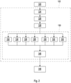
- the method comprises at least steps i) to iv), whereas an apparatus comprises parts I.) to IV.).
- a method and an apparatus for determining an authentication status of a suspect item are applied in order to determine the authentication status of the suspect item under investigation.
- the individual imperfection profile related to the suspect item is compared with the imperfection profile related to the original item.
- the method for determining the authentication status of the suspect item comprises at least steps a) to d), whereas an authentication apparatus at least comprises parts A) to D).
- a use of the authentication apparatus is disclosed for particularly preferred items. Since any of the methods according to the present invention may at least partially be performed using a computer-related implementation, a computer program including computer-executable instructions as well as a data carrier having a data structure stored thereon comprise further aspects of the present invention.
- the present invention relates to a method for generating and storing an individual imperfection profile related to an original item.
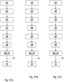
- the present method comprises the following steps step i) to iv).
- the steps i) to iv) are preferably performed in the given order, still, other orders may be feasible. Further, it may be feasible to perform two or more of the steps simultaneously or in an overlapping fashion. Further, it may also be feasible to perform one, two or more of the steps repeatedly, not depending on the fact whether other steps may be equally repeated. Further, additional steps may be comprised which are not mentioned in the following.
- the "item”, i.e. the original or the suspect item, may be any physical object to which a code, as defined further below, is assigned to.
- the item itself may be of any value or whether the item, such as a document or a packaging, refers to or comprises another item which may be of some value, either in a commercial view, a personal view, or any other view.
- a printed version of the code may thus be placed directly on the surface of the item.
- the printed version of the code may preferably not be printed onto the item itself but on a packaging of any kind which comprises the item.
- the item itself may be of a consistence, such as a gel, a liquid, a gas, or of any other form which may not exhibit a steady solid form, that a particular kind of packaging may be required for storing, transporting, trading, and any other action referring to the item.
- the surface of the item may not allow the consistent placing of the printed version of the code, e.g. in a case where the surface is too rough or too impermanent for consistently carrying the printed version of the code.
- the item may be furnished with any kind of packaging, for example, for any commercial or trading reason, such as for improving the storability, the durability, the stability, or the keeping properties of an item, for equipping the item with a packaging which comprises a specific style or design, particularly for transport or storage reasons, or for improving the optical appearance of the item such as for esthetic or trading reasons.
- a packaging which comprises a specific style or design, particularly for transport or storage reasons, or for improving the optical appearance of the item such as for esthetic or trading reasons.
- each substance which may comprise, within a first respect, a solid body, such as a powder, a pill, a tablet, or a preparation, within a second respect, a liquid, such as a liquid formulation, an emulsion, or a serum, or, within a third respect, a gas, such as an aerosol, are comprised in at least in one packaging, which may further be comprised itself in at least one additional packaging, which is usually referred to as "outer packaging".
- the "item” may, thus, refer to the physical object itself, to a label, a document, or any other article which may accompany the physical object, or to at least the one packaging which may comprise the physical object. Consequently, the item may not only be selected from the physical object itself but also from an accompanying article or from any other object which may be employed as the primary packaging for the physical object, such as a bottle, a syringe, a vial, an ampoule, a carpule, a blister, and/or a secondary packaging such as a cardboard box, a folding box, a hangtag, or any other outer packaging such as a plurality of folding boxes wrapped with plastic foil, called a bundle or a shipping carton, or a container.
- both the method for proving the authentication of the original item as well as the method for determining the authentication status of the suspect item may be applied under circumstances, wherein the physical object and/or an article accompanying the physical object and/or at least one packaging comprising the physical object may be proved or investigated with respect to the authenticity of the physical item and/or of the accompanying article and/or of the at least one packaging comprising the physical object.
- any of the methods may also be applied in a case where the printed version of the code is printed on both the primary packaging which comprises the physical object and the secondary packaging which comprises the primary packaging in order to determine the authentication status of the physical object itself, of the primary packaging and/or of the secondary packaging, such as at the same time.
- Such a procedure might be of particular relevance in situations where product safety and the way of transport must be ensured.
- the item may be considered as the "original item” as long as the item itself or a part thereof or a code, as will be defined further below, assigned to the item or a part thereof may be genuine and comprise no replica.
- a "suspect item” may be considered as an item which may not be identical with the original item but be or comprise a counterfeit item which may allegedly create an impression as being identical to the original item.
- the impression might be based on any evidence that the suspect item may differ with respect to any property from the original item, wherein such evidence may issue from a slightly different property of the suspect item, such as with respect to size, color, texture, or weight, among other corresponding properties, with respect to the known original item.
- the counterfeit may be accomplished in a quality that the suspect item may not show any such evidence which would make it distinguishable from the original item in this way. Consequently, a suspect item might be one of a group consisting of the original item and of the counterfeit item.
- the "code” may be defined as a machine-readable representation of data which are assigned to the item to which the printed version of the code is attached.
- the readability of the data by machine distinguishes the code from any other representation of data which relate to the item, such as printing the data in human readable form.
- a code may be read both by machine and by human beings, it may still be considered as a code according to the present invention as long as it can be recorded by machine.
- a set of rules exists which allows generating a specific code being assigned to a specific item upon providing specific data which are related to the specific item.
- Such an application of the set of rules allows generating a code, such as a linear or a one-dimensional barcode which generally represents data by varying the width and spacings of parallel lines, or a two-dimensional barcode which might represent data within an arrangement of bars, rectangles, squares, hexagons, or any other geometric pattern being distributed over a limited two-dimensional area, or a dot code which might comprise a specific number of dots also distributed over a limited two-dimensional area.
- the set of rules which allows generating the code to be assigned to the suspect item may be retrieved from a standard specification being laid out to define the code. World-wide, various standard specifications are used nowadays, however, with regard to the present invention the standard specification may preferentially be selected from the group consisting of:
- a code which may particularly be feasible to be used with regard to the present invention may comprise a plurality of modules, preferably at least 30 modules, more preferably at least 100 modules, most preferably at least 200 modules.
- the module of the code may be defined as the smallest unit within the code which may be able to represent data in a manner that such data may be optically read by a machine.
- a module may thus comprise a binary field, such as a bar, a rectangle, a round dot, an oval dot, a square, or a hexagon, the area of which geometrical pattern is filled with a specific color which can be optically distinguished by the employed machine from neighboring modules surrounding a specific module.
- each module may either comprise a black area, a white area, or an area in a specific color, or the opposite filling thereof, i.e. a white area, a black area, or a colored area in a different, preferably a complementary color with respect to the specific color.
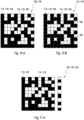
- the plurality of modules may be arranged in the form of an ideal image as a graphic representation of the code.
- the modules may be arranged one after the other in a line within the code whereas, in a two-dimensional code, the code may, thus, also be described as a two-dimensional matrix which may consist of rows and lines of modules.
- the main purpose of the code is to encode data which are assigned to the original item in a manner that at least one barcode content of the item is encoded within the plurality of modules, wherein the "barcode content” may allow establishing a specific relationship between the item and the representation of the item within the code.
- the barcode content may preferably comprise a numeric or an alphanumeric value being related to the item in a unique way.
- knowing a specific barcode content will allow identifying the specific item which is related to the specific barcode content by application of the set of rules according to which the code has been generated.
- knowing a specific code will allow to decoding the specific barcode content for the specific item which is related to the specific barcode content again by applying the set of rules as applied in the generation of the specific barcode content.
- the printed version of the code is printed onto the original item.
- the printing of the code onto the original item is performed with an original printing device which may apply any known printing technology, such as cartridge, continuous or “drop on demand” inkjet technologies, laser printing, thermo transfer printing, digital printing, etc. Consequently, each printing technology as applied by the original printing device may leave a kind of fingerprint resulting from printing the printed version of the code onto the original item.
- the code as printed by using two different printing devices may still be distinguishable due to unique features which may be inherently related to a specific printing device, such as caused by manufacturing tolerances and/or age symptoms, and/or which may depend on a specific setting of the printing device, such as a contrast, or a printing speed, among others.
- the printed version of the code generally differs from the ideal image of the plurality of modules as generated by applying the set of rules related to the code, whereby a numerical value for this kind of difference will be denoted as "individual imperfection profile" of the original printing device.
- the present invention may particularly allow distinguishing between the original printing device as being used in printing the code onto the original item and a different printing device that may be employed in printing the same code onto a counterfeit item by using the individual imperfection profile of the original printing device.
- step i) of the present method for generating and storing an individual imperfection profile related to an original item at least one picture of the printed version of the code printed onto the item is recorded by using an optical system.
- the present invention makes use of the fact that the printed version of the code as actually printed onto the item generally differs from the ideal image as generated by the set of rules for the corresponding code. The reasons for this difference are manifold but well-known.
- the main contributions may arise from vibrations of the infrastructure, particularly from the printing machine, from a variable viscosity of the inks involved, from the humidity of the ambient atmosphere, from the permeability of the nozzles, or from irregularities of the substrate material which may form the area of the surface of the item at which the printed version of the code may be located.
- the mentioned difference between the ideal representation of the code in the ideal image and the printed version of the code as actually printed on the item constitutes the basis for any of the methods according to the present invention.
- the "picture" may comprise an optical image of the printed version of the code as being recorded by the optical system.
- the picture may describe a one- or two-dimensional representation comprising a number of pixels in each dimension which together form the picture of the printed version of the code, thus constituting a basis for a further evaluation of the picture in order to extract the data relating to the item comprised within the code.
- various mechanisms have been introduced to ensure a readability of the code, in particular with regard to the symmetry and the contrast of the modules.
- the optical system being used for performing this task requires, for practical reasons, a comparatively low resolution of about 5 pixels per module and per dimension.
- the optical system which is configured for performing any of the methods according to the present invention may preferably comprise a resolution of 20 pixels per module per dimension or less, such as 3 to 15 pixels per module and per dimension, preferably 4 to 10 pixels per module per dimension, most preferably 5 pixels per module and per dimension.
- the "resolution” may refer to the ability of the optical system to resolve the mentioned number of pixels within the modules of the printed version of the code as printed onto the item.
- the optical system employed for performing any of the methods according to the present invention may comprise at least one element which may be selected from the group consisting of: a flatbed scanner, a camera, a barcode hand-scanning device, a cell or a cellular phone, a laptop webcam, a smartphone, a tablet computer.
- a flatbed scanner a camera
- a barcode hand-scanning device a cell or a cellular phone
- a laptop webcam a smartphone
- tablet computer any other optical system comprising a resolution which may be sufficient to resolve the modules in the printed version of the code may also be used.
- the mentioned step i) may comprise at least one of the following sub-steps i1) to i4).
- the picture of the printed version of the code may be located within a larger picture taken by the optical system, whereby the larger picture may not only comprise the picture of the printed version of the code but additional features.
- the larger picture of at least a part of the item may be taken in which the picture of the printed version of the code may be localized and defined, for example, through its coordinates of other specifications with regard to the position and/or rotation of the picture.
- sub-steps i2) and/or i3) may be applied.
- the picture may be rearranged with respect to a spatial orientation within the larger picture whereas, according to sub-step i3), the larger picture may be cut or cropped at least at one side and/or at one edge by which sub-steps i2) and/or i3) the picture of the printed version of the code itself may be acquired without the additional features which might be able to disturb the further processing of the picture.
- the rearranging of the spatial orientation of the picture may comprise at least one tilting step by which the at least one axis of the picture is aligned with a usually linear orientation (in one dimension) or with a usually rectangular orientation (in two dimensions) of the code.
- the two-dimensional picture may comprise two axes being lines crossing each other, thereby creating an angle with respect to each other, wherein the angle might preferably take a value of 90°, whereby, however, other values of the angle may be possible.
- the cutting of the picture may include a cutting step or cropping step during which a part of the features within the picture are removed from the larger picture usually along at least one straight line which discriminates the respective parts.
- sub-step i4) may be performed.
- the picture of the printed version of the code may be transformed into a binary format.
- the information comprised within the picture may generally be reduced in a manner that a specific module within the picture may only take one of two values of a Boolean variable, such as TRUE or FALSE, 1 or 0, black or white, or any other suitable designation.
- the at least one barcode content is decoded from the picture of the printed version of the code according to the set of rules as defined above.
- the decoding may be performed on the picture of the printed version as recorded by the optical system and/or from the picture which has been further modified by any one or more of the sub-steps i1) to i4) or any further or subsequent sub-step.
- the at least one barcode content which is related to the item has been acquired.
- step iii) irregularities in the same picture of the printed version of the code as used in step ii) are analyzed by identifying at least one deviation in the picture with respect to the ideal image and, further, calculating a numerical value which is denoted as an individual imperfection profile of the original printing device.
- this step may allow uniquely identifying a given code, wherein at least one deviation may be created in the picture of the printed version of the code during the printing process.
- a particular printed version of the code on a particular item may not necessarily comprise all possible deviations but, in practice, may only exhibit a selected number thereof which may be observed during the analyzing step iii).
- the methods according to the present invention are, thus, based on the reasonable assumption that a sum of the observed deviations in the particular printed version of the code on the particular item may be unique in a manner that any other printed version of the code may not be able to reproduce exactly the same deviations.
- the calculating of the numerical value representing the individual imperfection profile thus, depends on at least one unique feature inherently related to the printing device used for printing the particular printed version of the code on the particular item, wherein the at least one unique feature is selected from at least one of a printing technology and a setting of the printing device.
- analyzing step iii) may particularly ensure that irregularities which may be comprised within the printed version of the code may have actually been generated by the original printing device actually applied in printing the printed version.
- the analyzing step iii) may, thus, be able to detect a possible bypassing of the present method which may, for example, be performed by copying the code through high-resolution printing technology, such as offset printing.
- the printed version of the code could be copied by a high-resolution printing technology which may include copying the irregularities which may otherwise be produced arbitrarily by a low-resolution printing technique.
- the authentication status of the item may be determined as FALSE or 0 since the printed version of the code may have been printed by a different printing device, by which observation the conclusion may be drawn that the code may be a counterfeit, which means that due to the fact that the code is uniquely assigned to the item, the item may also be considered as a counterfeit.
- the analyzing step iii) may be performed on the raw version of the picture of the printed version of the code as recorded by the optical system and/or by using the picture in a modified way, in particular by applying one or more of the sub-steps i1) to i4) and/or any other modifying step with relation to the picture as recorded by the optical system.
- both the procedures according to step ii) and the procedures according to step iii) are performed on the same picture.
- the "same picture" may include the identical picture, an original picture recorded by the optical system and a picture modified according to the above-mentioned ways, two pictures which each may be modified in a different manner according to the above-mentioned ways, two subsequent exposures of the same printed version of the code by the same optical system, particularly within a short period of time, or any combination thereof.
- the analyzing step iii) comprises sub-steps iii1) and iii6), and may, in addition, comprise any or all of the sub-steps iii2) to iii5) or iii7), wherein the selected number of the sub-steps iii1) to iii7) may depend on at least one of the printing technology and the setting of the printing device.
- the selected sub-steps may be performed in the given order or in any other feasible order, as the skilled person will recognize. Further, two or more of the selected sub-steps may be performed in parallel or at least partially simultaneously. Further, one, two or all of the selected sub-steps may fully or partially be performed once or several times, i.e. repeatedly.
- step iii) may particularly concentrate on errors which randomly occur within the picture of the printed version of the code under investigation.
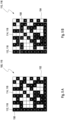
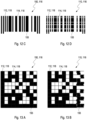
- the deviation between an area as effectively printed in the picture of module with respect to the area of the module in the ideal image may be determined, in particular the deviation between an area size as effectively printed in the picture of module with respect to the area size of the module in the ideal image.
- the deviation with respect to the area of a particular module may be defined as the difference between an ideal area of the particular module in the ideal image as generated according to the set of rules from an actual area of the module at the same place in the printed version of the code as printed in the picture of module by the employed printing device.
- the deviation of the at least one module with respect to its theoretical place may be analyzed, in particular, by taking into account that, from the ideal image, an ideal grid may be created which determines a boundary of the modules.
- the ideal grid may be defined as a set of successive straight lines, wherein the straight lines may be successively arranged in a parallel manner at regular distances. Whereas in a one-dimensional Cartesian coordination system one such set is sufficient to define the ideal grid, in a two-dimensional Cartesian coordination system two such sets are required. However, in a non-Cartesian coordination system, an adapted definition with respect to the respective orientation and the regular distance of the lines may be more suitable.
- the area of the at least one module inside its corresponding place within the real grid may, for example, be determined by a known method such as integrating the area, such as by computing a percentage of the area which is effectively printed.
- the deviation of the at least one module with respect to a grade of filling the area of the respective module may be analyzed. This deviation may result from an observation that the original printing device may not completely fill the area of at least one of the modules, in particular of a group of the modules or of all of the modules, during the printing process with a printing color, also denoted as printing ink.
- the printing device may successively fill the respective areas of the modules with printing ink in the form of geometrical figures which may not exhibit a rectangular or a square form, such as a circle or an oval, which may, thus, produce small areas without printing ink in the picture of the printed version of the code, in particular at the borders of the modules and/or at contact points of adjacent modules.
- the printing device may have at least one clogged nozzle, which may result in a missing line along the printed area within at least one of the modules in the picture of the printed version of the code.
- vibrations may occur during the printing process which may cause a distorted image in at least one affected module in the picture of the printed version of the code with respect to the ideal image, which may result in an amended filling of the area in the affected module.
- parallel lines or rectangles which may be used for defining the modules in the ideal image may be printed in a deviating shape by the printing device, in particular in a sinusoidal shape and/or as trapezoids.
- parameters suitable for defining the deviating shape may be employed in calculating the numerical value for the individual imperfection profile of the printing device.
- the deviation between the real grid as effectively printed in the picture and the ideal grid in the ideal image may be determined.
- the ideal image comprises no deviations
- the printing process might induce some irregularities which may result in deviations be observable in the picture of the printed version of the code.
- the ideal grid comprises two sets of parallel lines in a regular distance, wherein lines from a different set are arranged in right angles with respect to each other, whereas in the real grid which may be determined by the best fitting set of lines with respect to the boundary lines of each module, each line of the real grid may exhibit a positive or a negative value of an angle with respect to the ideal grid.
- a succession of the values of the angles and/or the tilting directions may create a unique representation with respect to the particular printed version of the code, wherein in a two-dimensional code, the values of the angles or the tilting directions, respectively, may be determined separately for both dimensions.
- parallel lines in the ideal grid may be printed in a deviating shape by the printing device, in particular in a sinusoidal shape.
- parallel lines in the ideal grid having a predefined distance with respect to each other, such as an equidistant arrangement may be printed in a deviating manner, such as in a non-equidistant manner, by employing the printing device. Parameters which may be suitable for describing the deviating shape and/or the non-equidistant arrangement may, thus, be used for calculating the numerical value for the individual imperfection profile of the printing device.
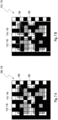
- the deviation between a real center of gravity of the module as effectively printed in the picture with respect to an ideal center of gravity of the module in the ideal image may be determined.
- the starting point of this method which is closely related to the method according to sub-step iii1) as described above and/or below, may comprise that each module may only be printed inside its respective boundaries as defined by the ideal grid. Consequently, if an effectively printed module may be crossing a line comprised in the ideal grid, the part of the module which may be located outside its boundaries as defined by the ideal grid may be assumed to belong to a different module.
- the center of gravity of a particular module may be determined by a known method which might be applied to calculate the center of gravity of a geometrical figure.
- a vector may be defined, wherein the resulting set of vectors, for all modules in the picture, may be considered as unique for each printed version of the code.
- a boundary curve as effectively printed in the picture may be determined as the deviation from a straight line in the ideal image.
- the deviation may be defined by a geometrical difference by which the boundary curve within the printed version of the code may deviate from an ideal straight line as defined in the code generated by the set of rules.
- the bottom line of the L-finder pattern in a data matrix code as defined above may not be printed as a straight line but rather as a boundary curve, wherein a combination of the curvature and the highest point of the boundary curve may be considered as unique for each data-matrix.
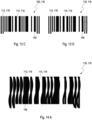
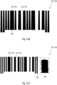
- each bar in the picture of the actually printed version of the linear barcode may exhibit an individual diffuse shape which might reveal a specific blurred boundary curve for each bar. This observation may be employed in the determination of the individual imperfection profile of the printing device, in particular, by recording an optical property, especially, a brightness, a refraction, or a transmission, preferably, along a curve which may, preferably, intersect each bar.
- each bar in the ideal image has a perfect linear shape and would, thus, produce a rectangular function in a diagram displaying an intensity of the recorded optical property along the line
- each bar in the picture of the actually printed version of the linear barcode can actually comprise an individual shape which may result in an individual signature which may exhibit a deviation from the rectangular function, which might, thus, be employed for determining the individual imperfection profile of the printing device.
- sub-step iii5) for at least one sub-group of modules in the picture of the printed version of the code, the deviation between the real center of gravity of the sub-group of modules effectively printed in the picture with respect to the ideal center of gravity of the sub-group of the modules in the ideal image may be determined.
- This method is closely related to the method according to sub-steps iii1) and iii3) as described above and/or below, but, in contrast thereto, may analyze a global deviation related to the at least one sub-group of modules within the picture instead of only local deviations related to at least one module, wherein the at least one sub-group of modules comprises at least two adjacent modules, preferably four or more adjacent modules, located together within a part of the ideal image and of the picture of printed version of the code.
- the deviation between a contrast in the module with respect to the contrast within a printed area in the picture may be determined.
- the contrast of each module may be defined as usual in photography and the printed area may comprise the picture of the printed version of the code or a part thereof.
- the contrast may be adjusted for each module in the actually printed version of the code, wherein the adjustment as required for each respective module may be taken into account for this purpose.
- a relative position of neighboring raster points of an underlying and/or an overprinted low-density image may be determined.
- This method may be based on the observation that in a printing process the representation of gradient areas is done by rasterizing. Hereby, an area usually appears darker the more raster elements it comprises.
- the printing device provides a pattern of raster points, wherein the position of the raster points with respect to the ideal grid in the ideal image may be applied for authentication purposes.
- the individual imperfection profile of the original printing device is finally calculated as a numerical value.
- the deriving of the numerical value of the imperfection profile neither requires classifying nor ranking the imperfections as recorded in the picture of the printed version of the code. Rather, identifying the deviations in the picture with respect to the ideal image, from which the numerical value which is denoted as the individual imperfection profile of the original printing device may be calculated, may, preferably, be performed without any prior analysis of the mentioned features.
- processing performance may express a number of operations which might be performed within a predefined time interval, such as one or more millions of operations within one or more seconds.
- the at least one barcode content of the suspect item as well as the at least one individual imperfection profile of the original item have been determined.
- the result will, during the following step iv) be employed for storing the individual imperfection profile onto the original item and/or in a database.
- the individual imperfection profile of the original item is stored by printing the individual imperfection profile onto the item and/or by generating a database record for the item, wherein the database record comprises at least the barcode content and the individual imperfection profile of the original item.
- printing the individual imperfection profile onto the item may be performed by the original printing device and/or any other printing device which may be adapted for this purpose.
- a database record is generated for each original item, wherein each database record comprises at least the database content and the individual imperfection profile of the respective original item, wherein the database content is derived from the barcode content of the original item and the individual imperfection profile is, further, derived from the original item in a unique fashion.
- Both ways of performance may allow referring later to the individual imperfection profile of the original item, either by reading the individual imperfection profile as printed on the original item and/or by selecting a database record, during step d) of the method for determining the authentication status of the suspect item as will be described later.
- a database record for determining the authentication status of the suspect item as disclosed below.
- the respective data might be stored in a fashion as derived or may undergo, prior to storing, one or more further procedures, such as a compression.
- the calculated numerical value may, thus, be compressed by using an autocorrelation of the related data prior to assigning it as the imperfection profile.
- a procedure which may comprise this advantage may be employed, such as an element generator.
- the "element generator” may comprise a method and/or a device which may be adapted to generate a library of elements, such as a collection of deviations, according to a predefined set of rules. Further, by comparing the respective elements within the library, it may be advantageous to select one or more elements thereof, preferably only a single element for further use. Within this regard, it may, further, be advantageous, not to store the numerical values as comprised within the selected element itself but rather a reference to the selected element. In addition, more than one binary result may be condensed into one or more bytes, preferably, without further compression, in particular due to, as mentioned above, an easy availability of huge and cheap data storage devices.
- the database record as generated during step iv) may be transmitted to the database via one or more channels selected from: a wireless data transmission, a wire bound data transmission, a transmission via a computer network.
- a wireless data transmission a wireless data transmission
- a wire bound data transmission a transmission via a computer network.
- the exact details and manners of the transmission are of little relevance as long as the generated database record is inserted into the database for further reference during step d) of the method for determining the authentication status of the suspect item.
- the method for proving the authentication of the original item may be part of one or more of a production process for producing the item, a process for producing an article accompanying the item, or a packaging process for packaging the item.
- This kind of performance particularly may ensure that the data which may be later required for a determination of the authentication status of the suspect item may be recorded within the database with little or no time delay, preferably directly within the production or the packaging line.
- Such an approach may particularly be useful for decreasing the hazard of counterfeit items whose authentication may be proved later by applying the respective method as presented here.
- a method for determining an authentication status of a suspect item is disclosed.
- the "authentication status" of a suspect item provides a value which defines whether the suspect item can be considered as the original item to be authenticated, or not, i.e. a counterfeit item.
- the item may be considered as the original item as long as the item itself or a part thereof or a code, as will be defined further below, assigned to the item or a part thereof may comprise no replica.
- the method for determining the authentication status may, within a first respect, comprise a method for determining a verification of a suspect item or, within a second respect, comprise a method for determining a falsification of a suspect item, depending on the purpose and/or circumstances under which the method may be performed.
- the present method may be performed in a case in which it is desired to confirm the authenticity of the suspect item.
- the present method may also be applied in a case in which the authenticity of the suspect item may be discarded for any reason.
- the method may also be used under circumstances in which it may be desired to find an answer to an open question whether the item under investigation may be the true original item to be verified or whether the suspect item may be a counterfeit item pretending to be the original item.
- the present method may deliver a Boolean value which may be designated by TRUE or FALSE, by 1 or 0, or by any other designation and which may comprise the authentication status of the suspect item determined by application of the present method.
- This Boolean value may further be used by the user of the present method for any purpose, e.g. as an entry into a specific database which may comprise such kind of values, for producing an optical signal or an audio signal or a signal of any other kind upon determining the suspect item to be a counterfeit item, or for separating the suspect item which may have been falsified by the method from an inspection line.
- the present method may be applied under various other circumstances and for any other purpose, which may particularly be based upon any specific need of the user.
- the method according to the present invention comprises the steps a) to d). These steps are preferably performed in the given order, starting with step a). However, the order of the steps may be altered in an arbitrary way, particularly by reversing the order of two consecutive steps. Further, one or more steps may be performed repeatedly, depending or not whether other steps are equally repeated. The method may further comprise one or more additional steps.
- step a) at least one picture of the printed version of the code as being printed onto the item is recorded.
- the same or a similar optical system which may already be employed in an inspection line for deriving the at least one barcode content of the item being encoded within the plurality of modules may also be used in the method for determining the authentication status of the suspect item.
- This particular embodiment may, therefore, allow using the same equipment for an additional purpose related to the authenticity of the suspect item, thus, avoiding the necessity of an upgrade of already existing facilities.
- the optical system may comprise the ability to record at least 5 pictures per minute, preferably at least 400 pictures per minute, more preferably at least 2000 pictures per minute. Such a feature may be of particular relevance for the applicability of the present method within high performance industrial lines.
- the authentication of the code may require a picture of a printed version of the code which may exhibit a reasonable quality and a sufficient resolution.
- the present authentication method may provide distorted results, such that a copy of the code may be mistaken for a genuine code one or vice-versa.
- Such a feature may be particularly applicable to the data matrix barcode. Therefore, it may be necessary to ensure, before performing any further processing of a given picture of a printed version of the code, that the picture may comprise a reasonable quality and resolution.
- the method according to the present invention does not depend on the resolution of the picture of a printed version of the code.
- the numerical value for the imperfection profile does not depend on the resolution of the picture, particularly not in a case in which a first picture of the printed version of the code as printed onto the original item is recorded with a different resolution than a second picture as recorded later from the same printed version of the same code on the same item which may, later, be considered as a suspect item.
- only such irregularities in the picture may be taken into account for deriving the imperfection profile which may not provide any problems with the above-mentioned comparatively low resolution, such as about 5 pixels per module and per dimension.
- the following procedure may, nevertheless, be applied for a quick and efficient analysis of a given picture of a printed version of the data matrix barcode.
- the picture of the data matrix barcode may be isolated from remaining parts of the picture, particularly by disregarding the remaining parts of the picture. Consequently, any poor quality and/or low resolution which might occur within the remaining parts of the picture may, thus, be excluded from disturbing the further processing of the picture.
- at least one of the following sub-procedures may be performed with regard to the picture of the printed version of the data matrix barcode:
- the exposition, the illumination, and the contrast of the picture may be defined as usually in photography and imaging.
- the exposition of the picture should preferably be corrected in a manner that the printed version of the data matrix barcode is fully depicted within the picture within a predefined range of tolerable deviations from an ideal image according to the code as defined by the set of rules.
- the illumination of the picture should preferably be evenly distributed over the area of the picture within a given range of tolerance.
- the contrast of the picture should exceed a predetermined threshold.
- blurring may usually occur due to an aberration caused by recording an image being out of focus. Consequently, any measure adapted for adjusting the focus into the plane of the picture of the printed version of the data matrix barcode might be helpful within this regard.
- a performance of each of these sub-procedures may be particularly adapted for being employed to the analysis of a picture of the printed version of a data matrix barcode in such a manner that it takes into account its binary nature.
- the given picture may be rejected and a further picture may be recorded by the optical system, in particular by employing the cell phone again. This procedure may be repeated unless a picture of the printed version of the data matrix barcode may be obtained which might exhibit the reasonable quality and the sufficient resolution for the further processing.
- the picture may be further modified by any one or more of the sub-steps i1) to i4) as described above for the method for proving the authentication of the original item.
- step b) of the present method for determining the authentication status of the suspect item the at least one barcode content is decoded from the picture of the printed version of the code according to the set of rules as defined above.
- the decoding may preferably be performed on the same picture of the printed version as recorded by the optical system and/or from the picture which has been further modified by any one or more of the sub-steps i1) to i4) or any further or subsequent sub-step.
- the at least one barcode content which is related to the item has been acquired.
- step c) irregularities in the same picture according to step iii) as described above and/or below are analyzed by identifying at least one deviation in the picture with respect to the ideal image and a numerical value which is denoted as an individual imperfection profile of the printing device is calculated.
- the at least one barcode content of the suspect item as well as the at least one individual imperfection profile of the suspect item have been acquired.
- the result will, during the subsequent step d), be employed to determine on this basis the authentication status of the suspect item.
- the individual imperfection profile reference may again be made to the disclosure of the method for proving the authentication of the original item, as disclosed above and/or below.
- step d) it is checked whether the code on the suspect item has been printed with the original printing device by comparing the individual imperfection profile of the suspect item with the stored individual imperfection profile of the original item.
- the individual imperfection profile which may have been printed on the original may be recorded, in particular by using the recording device which may be already employed in recording the picture of the printed version of the code according to step a) of the present method.
- the at least one barcode content of the suspect item is used to select a database record within a database which comprises a number of records in which at least both the database content and a individual imperfection profile of the original item which may preferably comprise a numeric value are stored.
- the record of the database may comprise a composite number which at least contains the database content and the individual imperfection profile of the respective original item.
- the at least one barcode content of the item is used to clearly identify the record in the database which is related to the barcode content and, in this manner, to obtain the individual imperfection profile being related to the suspect item, simultaneously. This way of procedure allows a direct, fast, and reliable selection of the database record related to the suspect item.
- the individual imperfection profile parameter of the suspect item as derived during step c) is compared with the individual imperfection profile of the original item as obtained during step d) within a comparing step.
- a comparison of the individual imperfection profile related to the suspect item with the individual imperfection profile related to the original item allows determining the authentication status of the suspect item.
- the "comparing step” includes comparing the individual imperfection profile of the suspect item with the individual imperfection profile of the original item with regard to their identity but also taking into account any tolerance levels within which the authenticity of the suspect item may be still assumed. Introducing tolerance levels may particularly allow taking into account inevitable adverse effects, such as deterioration, ageing, or wear, of the printed version of the code on the surface of the item.
- the present method for determining the authentication status of the suspect item may further comprise a transmission step by which, preferably after one or more of the method steps step a), step b), or step c), data may be transformed to a data processing unit via a computer network in such a manner that the further steps after the transmission may be performed by the data processing unit, wherein the authentication status of the suspect item may be returned by the data processing unit.
- This transmitting step may particularly be performed by at least one control unit which may be adapted to perform or to have performed at least method step a) as well the data transmission.
- the control unit may comprise a computer or a micro-computer, wherein the micro-computer may be part of the optical system, of a system which may control the optical system, or of a system which may be in connection with the optical system.
- Which kinds of data are transmitted by the control unit to the data processing unit may particularly depend at which stage during the performance of the present method the actual data transmission takes place.
- the at least one picture of the printed version of the code as recorded by the optical system may be transferred to the data processing unit on which the further steps b) to d) may be performed until the authentication status of the suspect item may be determined and returned to the at least one control unit.
- the at least one picture taken from the printed version of the code may first be modified according to step a) and the at least one barcode content of the item may also be derived from the picture according to the set of rules according to step b) before the modified picture together with the at least one barcode content may be transmitted by the at least one control unit to the data processing unit for performing the further steps c) and d) until the authentication status of the item may be determined and returned to the at least one control unit.
- the steps a) to c) may be performed locally until the control unit may transmit the at least one barcode content together with the individual imperfection profile determined for the suspect item to the data processing unit where only the remaining step d) may be performed until the authentication status of the suspect item may be determined and returned to the at least one control unit.
- the database may be one or more of comprised within the processing unit or operationally connected to the data processing unit.
- an apparatus for generating and storing an individual imperfection profile related to an original item is disclosed.
- a code is assigned to the item according to a set of rules, wherein the code comprises a plurality of modules arranged in an ideal image, wherein at least one barcode content of the item is encoded within the plurality of modules, wherein at least one printed version of the code is printed onto the item with a printing device.
- the apparatus comprises at least the parts I.) to IV.), which may be arranged in any suitable order. Further, additional parts may be comprised in the apparatus which are not mentioned in the following.
- the parts may be part of one combined apparatus or centralized unit or may be combined in different apparatuses or de-centralized units, wherein the apparatuses are adapted to interact in any suitable fashion, such as by wire-bound communication and/or wireless communication.
- Part I.) of the apparatus comprises a recording device configured for recording at least one picture of the printed version of the code printed onto the item
- part II.) comprises a decoding device configured for decoding the barcode content from the picture
- Part III.) comprises an analysis device configured for analyzing irregularities in the picture by identifying at least one deviation in the same picture with respect to the ideal image and for calculating a numerical value which is denoted as an individual imperfection profile of the printing device.
- Part IV.) of the apparatus comprises a storing device for storing the individual imperfection profile, wherein the storing device comprises the same or a further printing device configured for printing the individual imperfection profile onto the item and/or a generating device configured for generating a database record for the item.
- each database record comprises at least the barcode content and the individual imperfection profile of the respective original item.
- the apparatus is configured to perform the method for generating and storing an individual imperfection profile related to the original item as described above and/or below.
- the apparatus may be part of one or more devices which are selected from: a production apparatus for producing the item, an apparatus for producing an article which accompanies the item, or a packaging apparatus for packaging the item.
- This kind of embodiment may be particularly useful for strictly combining the production and/or the packaging of the item with the apparatus which generates the database record being related to the item.
- This arrangement may particularly allow ensuring that the individual imperfection profile as stored on the item and/or in the database record may actually be related to the item to which it may allegedly belong.
- Such a strong physical relationship of the mentioned devices may be particularly intended to reduce the counterfeit hazard with relation to items of some value.
- an authentication apparatus for determining the authentication status of the suspect item.
- a code is assigned to the item according to a set of rules, wherein the code comprises a plurality of modules arranged in an ideal image, wherein at least one barcode content of the item is encoded within the plurality of modules, wherein at least one printed version of the code is printed onto the item with a printing device.
- the authentication apparatus at least comprises parts A) to D), which may be assembled in any suitable fashion. Further, additional parts may be comprised within the authentication apparatus which are not mentioned in the following. The parts may be part of one combined apparatus or centralized unit or may be combined in different apparatuses or de-centralized units, wherein the apparatuses are adapted to interact in any suitable fashion, such as by wire-bound communication and/or wireless communication.
- Part A) of the authentication apparatus comprises a recording device configured for recording at least one picture of the printed version of the code printed onto the item, whereas part B) comprises a decoding device configured for decoding the barcode content from the picture.
- Part C) comprises an analysis device configured for analyzing irregularities in the picture by identifying at least one deviation in the same picture with respect to the ideal image and for calculating a numerical value which described an individual imperfection profile of the printing device.
- Part D) comprises a comparing device configured for comparing the individual imperfection profile of the suspect item with the individual imperfection profile of the original item, by which comparison the authentication status of the suspect item is determined.
- the authentication apparatus may be configured to perform the method for determining the authentication status of the suspect item as described above and/or below.
- the authentication apparatus may be further adapted to control the transmission of data to a data processing unit.
- the transmission of the data may be performed via one or more transmission means selected from a wireless data transmission, a wire bound data transmission, and/or a transmission via a computer network. Further details concerning the data transmission, the data and the data processing unit may be found elsewhere in this description.
- the authentication apparatus may preferentially be used for an authentication of suspect items which carry a code, wherein the item is at least one item or comprises at least one item selected from the group consisting of:
- the invention further discloses and proposes a computer program, including computer executable instructions for performing both the method for generating and storing an individual imperfection profile related to the original item and the hereto related method for determining the authentication status of the suspect item, when the program is executed on a computer or a computer network.
- the computer program may be stored on a computer readable data carrier.
- the invention further discloses a data carrier having a data structure stored thereon, which, after loading into a computer or a computer network, is capable of executing any or all methods as disclosed herein.
- a computer may comprise any device which may be capable of storing data and/or performing calculating steps and/or instructing steps.
- this definition may not only include work stations and notebooks but also application-specified integrated circuits (ASICs) and field-programmable gate arrays (FPGAs).
- one or more of the method steps or even all of the method steps of any or all methods disclosed herein may be performed by using a computer or a computer network.
- any of the method steps including provision and/or manipulation of data may be performed by using a computer or a computer network.
- these method steps may include any of the method steps.
- the invention further discloses and proposes a computer program including computer-executable instructions for performing any or all methods according to the present invention in one or more of the embodiments enclosed herein when the program is executed on a computer or computer network.
- the computer program may be stored on a computer-readable data carrier.
- one, more than one or even all of method steps as indicated above may be performed by using a computer or a computer network, preferably by using a computer program.
- the invention further discloses and proposes a computer program product having program code means, in order to perform any or all methods according to the present invention in one or more of the embodiments enclosed herein when the program is executed on a computer or computer network.
- the program code means may be stored on a computer-readable data carrier.
- the invention discloses and proposes a data carrier having a data structure stored thereon, which, after loading into a computer or computer network, such as into a working memory or main memory of the computer or computer network, may execute any or all methods according to one or more of the embodiments disclosed herein.
- the invention further proposes and discloses a computer program product with program code means stored on a machine-readable carrier, in order to perform any or all methods according to one or more of the embodiments disclosed herein, when the program is executed on a computer or computer network.
- a computer program product refers to the program as a tradable product.
- the product may generally exist in an arbitrary format, such as in a paper format, or on a computer-readable data carrier.
- the computer program product may be distributed over a data network.
- the invention proposes and discloses a modulated data signal which contains instructions readable by a computer system or computer network, for performing any or all methods according to one or more of the embodiments disclosed herein.
- one or more of the method steps or even all of the method steps of any or all methods according to one or more of the embodiments disclosed herein may be performed by using a computer or computer network.
- any of the method steps including provision and/or manipulation of data may be performed by using a computer or computer network.
- these method steps may include any of the method steps, typically except for method steps requiring manual work, such as providing the samples and/or certain aspects of performing the actual measurements.
- the methods and devices according to the present invention are considerably distinguished from known methods and devices according to the state of the art and, thus, provide a number of advantages with regard to the state of the art.
- the present method and apparatus for determining the authentication status of a suspect item may readily be employed within new or existing industrial facilities comprising optical systems.
- the barcodes may be printed onto the items for serializing single products.
- optical systems configured for decoding the barcodes may be used.
- various standards may be available. Since these standards, as mentioned, may be generally focused on the readability of the barcodes, they may rely on examining symmetry and/or contrast ratio of the barcode by determining mean values of such kinds of parameters.
- the readability of barcodes is generally not impaired by errors occurring within a module.
- appropriate algorithms are used in order to provide the quality of barcodes printed on items or to ensure their readability despite such errors, see e.g. WO 01/53101 A1 .
- the present methods rather concentrate on irregularities which usually occur randomly in the picture of the printed version of the code, a feature which particularly qualifies them to be suitable for such a purpose.
- these kinds of irregularities may, therefore, be used, alternatively and/or in addition to their known use, for proving and/or determining the authentication of a code being related to an item. Consequently, analyzing procedures which may be employed within the present method may, thus, generally not be the same as procedures used for other purposes.
- the present method for determining the authentication status of a suspect item may be employed within industrial facilities for a fast and still reliable authenticating of a plurality of items.
- the present invention may allow making use of existing recording devices which may be already adapted for recording print images with speeds and typically low resolutions, such as approx. 5 pixels per module, as generally employed within industrial facilities. These properties may constitute a particularly attractive feature since less effort and fewer adaptions to known systems and procedures may facilitate an implementation of the present invention.
- the present method may be performed at a speed being much faster than any other known authentication method.
- a further advantage may be found in the observation that the barcode content being already decoded within the barcode may, after decoding preferably within the same picture as, nevertheless, required for the authentication procedure, be used for a fast and purposeful identification of the suspect item through a database record further comprising data which are related to the authentication of the item.
- this advantage particularly may reduce the requirements for a discriminability of authentication data and, at the same time, may decrease the possibility of a false-positive or a false-negative identification.
- Figure 1 shows a typical example of a picture 110 of a printed version of a data matrix barcode.
- the data matrix barcode is defined as a two-dimensional code which comprises a number of black modules 112 and a number of white modules 114 being arranged in a square or in a rectangular pattern 116.
- the barcode which may be expressed in the pattern 116 is assigned to an item (not depicted here) in a manner that a data matrix barcode content related to the item is encoded within the plurality of modules 118.
- the data matrix barcode may allow identifying details about the related item, such as a manufacturer, a part number and a unique serial number, which may be together be referred to the barcode content of the item.
- a further example such as schematically depicted in Figures 9C , 11B , 12C and D , 13C and D , and 14 A to C , may be a one-dimensional or linear barcode, wherein the number of black modules 112 and the number of white modules 114 are usually arranged in a linear pattern 116.
- a preferred embodiment for the method for proving the authentication of the original item is drawn.
- a plurality of original items may be provided wherein the picture 110 of the printed version of each code may be printed onto the respective item.
- a code may be assigned to each item according to the set of rules, which, in this example, may be extracted from the standard specification which defines the data matrix barcode.
- the data matrix barcode comprises a plurality of modules in such a manner that the barcode content of the item may be encoded within the plurality of modules.
- the deriving step 122 may comprise a number of sub-steps, which may be preferably performed according to the following order.
- the printed version of the data matrix barcode may, according to step i), be recorded by means of an optical system.
- a modifying step 126 may be applied to the picture of the printed version of the code, which may comprise at least one of the following sub-steps:
- the at least one barcode content referring to the item may, according to step ii), be decoded within a decoding step 128.
- the same picture 110 of the printed version of the code as previously used in the decoding step 128 is used for acquiring a individual imperfection profile related to original printing device which has been actually used for printing the code onto the item.
- irregularities in the picture 110 of the printed version of the code may be analyzed by identifying at least one deviation in the picture 110 of the printed version of the code with respect to the ideal image as determined by an application of the set of rules to the data matrix barcode.
- this task may be performed by one or more of the following sub-steps, wherein, for the purposes of the present invention, the analyzing step iii) comprises sub-steps iii1) and iii6), and may, in addition, comprise any or all of the sub-steps iii12) to iii5) or iii7):
- step iii) a numerical value which is denoted as the individual imperfection profile of the original printing device may then be calculated.
- the individual imperfection profile of the original printing device which may have been used to effectively print the data matrix barcode on the suspect item may be acquired, wherein the individual imperfection profile may preferably comprise at least one numeric value.
- the individual imperfection profile may be stored, in a first embodiment, by printing the individual imperfection profile onto the item and, in a second embodiment, additionally or alternatively by generating a database record for the item, wherein the database record comprises at least the barcode content and the individual imperfection profile being related to the original item.
- the preferred embodiment for the method for proving the authentication of the original item may, thus, comprise the following steps and/or sub-steps: 120 Providing step: providing a plurality of original items, wherein a code may be assigned to each item according to the set of rules, which may be extracted from the standard specification which defines the data matrix barcode; 122 Deriving step: deriving a individual imperfection profile of the original printing device for each item, wherein the deriving step may comprise the sub-steps 124 to 130 and 146; 124 126 Recording step: recording the picture 110 of the printed version of the data matrix barcode printed onto the item by means of an optical system; Modifying step: modifying the picture 110 of the printed version of the code, which may comprise at least one of the following sub-steps: - locating the picture 110 of the printed version of the code; - rearranging a spatial orientation of the picture 110; - cutting or cropping the picture at least at one side and/or at one edge; - transforming the
- Figure 3A schematically depicts the arrangement within an ideal image 150 of a data matrix barcode created by applying the set of rules as retrieved from the standard specification defining the data matrix barcode.
- a two dimensional ideal grid 152 as represented in Figure 3A by two sets of parallel dashed lines which cross each other under an angle of 90° may form a square pattern 116 of a number of 10 x 10 modules 118 which are either black modules 112 or white modules 114.
- Figure 3B shows an actual real data matrix barcode, i.e. the picture 110 of the printed version of the data matrix barcode as effectively printed onto the item.
- the differences to the square pattern 116 of the ideal image 150 can be discovered at first sight, although in this particular example a real grid 154 remains identical with the ideal grid 152 and only a positional deviation between the pattern 116 of the code in the ideal image 150 and in the picture 110 of the printed version of the code has occurred.
- a real grid 154 remains identical with the ideal grid 152 and only a positional deviation between the pattern 116 of the code in the ideal image 150 and in the picture 110 of the printed version of the code has occurred.
- other kinds of deviations with respect to the ideal image 150 may further be observed.
- sub-step iii1) the deviation between an area 155 of the modules 118 as effectively printed in the picture 110 of the printed version of the code in Figure 3B with respect to the area 155 of the modules 118 in the ideal image 150 in Figure 3A may be determined.
- all modules 118 perfectly fit inside the ideal grid 152
- some modules 118 may be slightly shifted with respect to the real grid 154.
- the area 155 of the modules 118 inside its corresponding place within the real grid 154 may, for example, be determined by integrating the area, such as by computing a percentage of the area being effectively printed.
- Further examples for deviations in a sense according to sub-step iii1) may be found in Figures 10 , 12 , 13 and 14 .
- Figure 4A displays a real data matrix barcode, i.e. the picture 110 of the printed version of the data matrix barcode as effectively printed onto the item.
- the differences to the square pattern 116 of the ideal image 150 here comprise a distortion of the ideal grid 152 of the ideal image 150 into the real grid 154 of the picture 110 of the printed version of the code.
- Figure 4B schematically depicts, as an example, one set of parallel lines which form the real grid 154 in one of the two dimensions of the data matrix barcode.
- the lines of the real grid 154 may be tilted in a positive (+) direction or in a negative (-) direction with respect to the lines in the ideal grid 152 or may be identical with the lines in the ideal grid 152.
- the same phenomenon may be observed in the other set of parallel lines in the second dimension.
- the deviation between the real grid 154 as effectively printed in the picture 110 of the code and the ideal grid 152 in the ideal image 150 may be determined by the best fitting set of lines with respect to the boundary lines of each module 118.
- a succession of the values of the tilting directions may create a unique representation with respect to the picture 110 of the printed version of the code, wherein the values of the tilting directions may be determined separately for both dimensions.
- Further examples for deviations in a sense according to sub-step iii2) may be found in Figures 11 and 14 .
- Figure 5A displays the ideal center of gravity 156 for the module 118 within the ideal image 150 of a data matrix barcode which may exactly be located in the center of each square 116 as defined by the ideal grid 152 in the ideal image 150 of the data matrix barcode.
- the real center of gravity 158 of the same module 118 in the picture 110 may no longer be at the position of the ideal center of gravity 156 of the same module 118 in the ideal image 150.
- the deviation between the real a center of gravity 158 of the module 118 as effectively printed in the picture 110 as presented in Figure 5B with respect to the ideal center of gravity 156 of the same module 118 in the ideal image 150 as depicted in Figure 5A may be determined by taking into account that the module 118 may only be printed inside its respective boundaries as defined by the ideal grid 152. Consequently, if the effectively printed module 118 may be crossing a line as comprised in the ideal grid 152, the part of the module 118 which may be located outside its boundaries as defined by the ideal grid 152 may be assumed to belong to a different module.
- the real center of gravity 158 of the module 118 may be determined by a known method applicable to calculate the center of gravity of a geometrical figure.
- a vector may be defined, wherein the resulting set of vectors may be considered as unique for the picture 110 of the printed version of the code.
- Figure 6 schematically shows a boundary curve 160 as effectively printed in the picture 110 of the code which deviates from a straight line in the ideal image 150 as for example shown in Figures 3A and 5A .
- the deviation comprises a geometrical difference by which the boundary curve 160 within the picture 110 may deviate from an ideal straight line in the ideal image 150.
- the bottom line of the L-finder pattern in the data matrix code as shown in Figure 6 has not been printed as a straight line but as the boundary curve 160.
- a combination of the curvature and the highest point of the boundary curve 160 may be considered as unique for the picture 110 of the printed version of the code.
- Figure 7A displays the ideal center of gravity 156 for a sub-group 162 of modules within the ideal image 150 of a data matrix barcode, wherein the sub-group 162 here comprises a number of adjacent modules located together within a part of the ideal image 150.
- the real center of gravity 158 of the same sub-group 162 of modules in the picture 110 of the printed version of the code may no longer be at the position of the ideal center of gravity 156 of the same sub-group 162 of modules.
- the deviation between the real a center of gravity 158 of the sub-group 162 of modules as effectively printed in the picture 110 as presented in Figure 7B with respect to the ideal center of gravity 156 of the same sub-group 162 of modules in the ideal image 150 as depicted in Figure 7A may be determined as described above.
- a vector may be defined, wherein the resulting set of vectors may be considered as unique for the picture 110 of the printed version of the code.
- Figure 8 displays an example of a picture 110 of the printed version of the code which comprises a number of raster points 164 belonging to an underlying and/or an overprinted low-density image.
- the printing device may provide an underlying and/or an overprinted low-density image which may comprise a pattern of raster points 164, wherein, according to sub-step iii7), the position of the raster points 164 with respect to the ideal grid 152 in the ideal image 150 may be suitably used for authentication purposes.
- Figure 9A schematically shows an ideal image 150 of a data matrix barcode which is compared with the picture 110 of an actually printed version of the data matrix barcode according to Figure 9B , wherein the irregularities comprise a deviation 142 with respect to a contrast in the module.
- Figure 9C a comparison between the ideal image 150 of a linear barcode (upper half of Figure 9C ) and a picture 110 of an actually printed version of the linear barcode with irregularities with respect to the contrast (lower half of Figure 9C ) are schematically depicted.
- the picture 110 of the actually printed version of the code may exhibit a weak, but optically discernible difference in contrast between two different modules 118 as illustrated in Figure 9B for the example of a data matrix barcode and in the lower half of Figure 9C for the example of a linear barcode.
- the contrast may be adjusted for each module 118 in the actually printed version of the code, wherein the adjustment as required for each respective module may be taken into account for this purpose.
- Figure 10A schematically depicts an ideal image 150 of a data matrix barcode
- Figure 10B shows a picture 110 of an actually printed version of the data matrix barcode, wherein the effectively printed area 155 of the modules 118 deviates, according to sub-step iii1), from the area 155 of the modules 118 in the ideal image 150 due to printing ink which may be missing between adjacent modules 118, thus reducing the printed area 155 in the picture 110 with respect to the corresponding area 155 in the ideal image 150.
- Figure 11A schematically presents a picture 110 of an actually printed version of a data matrix barcode
- Figure 11B shows a picture 110 of an actually printed version of a linear barcode.
- a deviation according to sub-step iii2) with regard to the ideal grid 152 in terms of a predefined distance of the modules 118 in the ideal image 150 as, for example, depicted in Figure 9A for data matrix barcode and in the upper half of Figure 9C for the linear barcode may be observed.
- the real grid 154 in the picture 110 of the actually printed version of the code may exhibit differing distances between different modules 118, such as with respect to their location and/or their width, particularly in printing direction.
- Figures 12A and 12C schematically show an ideal image 150 of a data matrix barcode ( Fig. 12A ) and of a linear barcode ( Fig. 12C ), respectively.
- Figures 12B and 12D each display a picture 110 of an actually printed version of the data matrix barcode ( Fig. 12B ) and of a linear barcode ( Fig. 12D ), respectively, wherein, according to sub-step iii1), the effectively printed area 155 of the modules 118 deviates from the area 155 of the modules 118 in the ideal image 150 due to at least one missing line along the printed area, particularly in printing direction.
- Such a kind of deviation may be a result from a printing device which comprises at least one nozzle that may be clogged and, thus, may at least only partially contribute to the application of printing ink onto the item.
- the individual imperfection profile of the printing device may be derived from a parameter related to the at least one missing line, such as a width and/or a position of the missing line.
- Figures 13A and 13C schematically show an ideal image 150 of a data matrix barcode ( Fig. 13A ) and of a linear barcode ( Fig. 13C ), respectively.
- Figures 13B and 13D each display a picture 110 of an actually printed version of the data matrix barcode ( Fig. 13B ) and of a linear barcode ( Fig.
- the effectively printed area 155 of the modules 118 deviates from the area 155 of the modules 118 in the ideal image 150 due to vibrations arising during the printing process, in particular at the end of the printing process, thus, resulting in a rather poor quality of the corresponding modules 118 which may exhibit a distorted form at the respective locations within the pattern 116.
- the individual imperfection profile of the printing device may be derived from a location related to the at least one distorted module within the pattern 116.
- Figure 14 schematically presents pictures 110 of actually printed versions of linear barcodes which may constitute a deviation according to sub-step iii1) with regard to the area 155 of the modules 118 in the ideal image 150 and/or according to sub-step iii2) with regard to the ideal grid 152 and/or according to sub-step iii4) with regard to the boundary curve 160.
- a bar in the ideal image 150 has as, for example, shown in Fig. 13C , a perfect linear shape
- each bar in the picture 110 of the actually printed versions of the linear barcode in Figure 14A exhibits a sinusoidal variation along its extension which may, alternatively or additionally, be employed for deriving the individual imperfection profile of the printing device from a parameter in relationship to the sinusoidal variation.
- each bar in the picture 110 of the actually printed versions of the linear barcode in Figure 14B displays a trapezoid variation of the diameter of the bars with an increasing diameter towards the lower bottom of each bar, which may, alternatively or in addition, be employed for deriving the individual imperfection profile of the printing device from a parameter related to the trapezoidal variation.
- the shape of the bars of a barcode in the picture 110 may be composed of a large number of small, irregular bubbles, as schematically depicted in Figure 14C .
- the bubble may be arranged highly irregular in a manner that at least one boundary curve 160 of a bar may constitute a parametric curve, whose parameters may be employed in deriving the individual imperfection profile of the printing device.
- each bar in the picture 110 of the actually printed version of the linear barcode in Figure 14D may exhibit an individual diffuse shape which might reveal a specific blurred boundary curve 160 for each bar.
- This observation may be taken into account for determining the individual imperfection profile of the printing device by, additionally, recording an optical property, such as a brightness, a refraction, or a transmission, along a curve, preferably a straight line 165A or a curved line 165B which may, preferably, be arranged in a manner that it might intersect each bar in an angle which may depend on an allocation of most dominant defects as schematically depicted in Figure 14D .
- each bar in the ideal image 150 as for example shown in Figure 13C has a perfect linear shape and would, thus, produce a rectangular function in a diagram, in which the intensity 165C of the selected optical property might be displayed along the straight line 165A (as shown in Figure 14E ) or along the curved line 165B (not depicted here)
- each bar in the picture 110 of the actually printed versions of the linear barcode in Figure 14D can comprise an individual shape which may result in an individual signature which might exhibit a deviation from the rectangular function as depicted in Figure 14E . Consequently, the deviation from the rectangular function may be employed for calculating a numerical value, which may be used for describing the individual imperfection profile of the printing device.
- the embodiment as described in Figure 15A starts with the recording step 124 during which according to step a) at least one picture 110 of the printed version of the code may be recorded with an optical system. Thereafter, the picture 110 may undergo a modifying step 126 which has been described elsewhere in more detail. With the subsequent decoding step 128, the at least one barcode content of the item may, according to step b), be decoded from the picture 110 according to the set of rules. According to step c), after performing the analyzing step 130 which may provide irregularities in the picture 110 of the printed version of the code by identifying at least one deviation in the picture 110 with respect to the ideal image 150, a numerical value which is denoted as the individual imperfection profile of the original printing device may be calculated in a calculating step 146.
- the individual imperfection profile of the suspect item as determined within the previous calculating step 146 may then be transmitted within a transmission step 166 to a data processing unit via a computer network. Thereafter, within a selecting step 168, the barcode content may be used to select a database record and, thus, obtain the individual imperfection profile of the original item which may be related to the item.
- the individual imperfection profile of the original item may then, according to step d), be used within a comparing step 170 in order to compare the individual imperfection profile of the suspect item with the individual imperfection profile of the original item, by which comparison an authentication status 172 of the suspect item may be determined and subsequently returned in a returning step 174 to a control unit which requests this kind of information.
- the first preferred embodiment for the method for determining the authentication status 172 of the suspect item 180 may comprise the following steps: 124 Recording step: recording the picture 110 of the printed version of the data matrix barcode printed onto the item by means of an optical system; 126 Modifying step: modifying the picture 110 of the printed version of the code; 128 Decoding step: decoding the at least one barcode content referring to the item; 130 Analyzing step: analyzing irregularities in the picture 110 by identifying at least one deviation in the picture 110 with respect to the ideal image; 146 Calculating step: calculating a numerical value which is denoted as the individual imperfection profile of the suspect item; 166 Transmission step: transmitting the individual imperfection profile of the suspect item to a data processing unit via a computer network; 168 Selecting step: obtaining the individual imperfection profile of the original item related to the item by typically using the barcode content to select a database record; 170 Comparing step: comparing the individual imperfection profile of the suspect item with the individual
- the second embodiment may provide the authentication status 172 of the suspect item.
- the second preferred embodiment for the method for determining the authentication status 172 of the suspect item 180 may comprise the following steps: 124 Recording step: recording the picture 110 of the printed version of the data matrix barcode printed onto the item by means of an optical system; 126 Modifying step: modifying the picture 110 of the printed version of the code; 128 Decoding step: decoding the at least one barcode content referring to the item; 166 Transmission step: transmitting the modified picture of the printed version of the code to a data processing unit via a computer network; 130 Analyzing step: analyzing irregularities in the picture by identifying at least one deviation in the picture with respect to the ideal image; 146 Calculating step: calculating a numerical value which is denoted as the individual imperfection profile of the suspect item; 168 Selecting step: obtaining the individual imperfection profile of the original item related to the item by typically using the barcode content to select a database record; 170 Comparing step: comparing the individual imperfection profile of the suspect item with the individual imperfecti
- a third embodiment as schematically depicted in Figure 15C may also provide the authentication status 172 of the suspect item.
- only the recording step 124 may locally be performed before the picture 110 of the printed version of the code may be transmitted, with the transmission step 166, to the data processing unit via the computer network, whereas the remaining steps, including the modifying step 126, the decoding step 128, the analyzing step 130, the calculating step 146, the selecting step 168, the comparing step 170, and the returning step 174 may be performed.
- the third preferred embodiment for the method for determining the authentication status 172 of the suspect item 180 may comprise the following steps: 124 Recording step: recording the picture 110 of the printed version of the data matrix barcode printed onto the item by means of an optical system; 166 Transmission step: transmitting the picture 110 of the printed version of the code to a data processing unit via a computer network; 126 Modifying step: modifying the picture 110 of the printed version of the code; 128 Decoding step: decoding the at least one barcode content referring to the item; 130 Analyzing step: analyzing irregularities in the picture by identifying at least one deviation in the picture with respect to the ideal image; 146 Calculating step: calculating a numerical value which is denoted as the individual imperfection profile of the suspect item; 168 Selecting step: obtaining the individual imperfection profile of the original item related to the item by typically using the barcode content to select a database record; 170 Comparing step: comparing the individual imperfection profile of the suspect item with the individual imperfecti
- Figure 16 schematically depicts a preferred authentication apparatus 176 which is configured for performing the method for determining the authentication status 172 according to the first embodiment as schematically presented in Figure 15A .
- a recording device 178 may, according to part A), be configured for recording the picture 110 of the printed version of a data matrix barcode which may have been printed onto an item 180, such as a bottle which might comprise a pharmaceutical preparation.
- the recording of the picture 110 may be supported by a light source 182 which may illuminate the picture.
- the authentication apparatus 176 may, according to part B), further comprise a decoding device 184 which may be configured for decoding the at least one barcode content from the picture 110 of the printed version of the code according to the set of rules applicable to the data matrix barcode.
- a further part of the authentication apparatus 176 may, according to part C), be the analyzing device 186 configured for analyzing irregularities in the picture 110 in order to derive the at least one individual imperfection profile of the printed version of the code as printed on the suspect item 180.
- the authentication apparatus 176 may further comprise a selecting device 188 configured for selecting, within a database 190, a database record 192 by using the barcode content to search for a database content 194 and also configured for obtaining an individual imperfection profile 196 of the original item 180 from the database record 192, wherein the individual imperfection profile 196 of the original item 180 comprises a numeric value.
- a selecting device 188 configured for selecting, within a database 190, a database record 192 by using the barcode content to search for a database content 194 and also configured for obtaining an individual imperfection profile 196 of the original item 180 from the database record 192, wherein the individual imperfection profile 196 of the original item 180 comprises a numeric value.
- the database may be accessible via a transmission line 198 by which data may be transmitted from the selecting device 188 to the database 190 and by which the individual imperfection profile 196 of the original item 180 is returned back to the comparing device 200 being configured, according to part D), for comparing the individual imperfection profile 196 of the suspect item 180 as obtained by means of the analyzing device 186 with the individual imperfection profile 196 of the original item 180 transmitted by the transmission line 198 from the database 190.
- This comparison which may be performed within the comparing device 200 of the authentication apparatus may finally allow determining the authentication status 172 of the suspect item 180.
- the preferred authentication apparatus 176 configured for performing the method for determining the authentication status 172 according to the first embodiment as depicted in Figure 15A may comprise the following parts: 178 Recording device: a device configured for recording the picture 110 of the printed version of a data matrix barcode printed onto an item 180 supported by a light source 182; 184 Decoding device: a device configured for decoding the at least one content from the picture of the printed version of the code; 186 Analyzing device: a device configured for analyzing irregularities in the picture 110 of the printed version of the data matrix barcode in order to derive the at least one individual imperfection profile 196 of the printed version of the data matrix barcode as printed on the suspect item 180; 188 Selecting device: a device configured for selecting, within a database 190, a database record 192 by using the barcode content to search for a database content 194 and also configured for obtaining an individual imperfection profile 196 of the original item 180 from the database record 192; 200 Comparing device: a
- Figure 17 schematically displays a preferred embodiment of an apparatus 202 which is configured for generating and storing an individual imperfection profile 196 related to an original item 180.
- a code is assigned to the item 180 according to a set of rules, wherein the code comprises a plurality of modules 118 which are arranged in an ideal image 150.
- at least one barcode content of the item 180 is encoded within the plurality of modules 118, wherein at least one picture of the printed version of the code is printed onto the item 180 with a printing device.
- the apparatus 202 may comprise a providing device 204 configured for providing a plurality of original items 180, wherein a picture 110 of the printed version of each code may be printed onto the respective item 180.
- each item 180 may comprise a unique code being expressed in a unique picture 110 of the printed version of the code.
- the apparatus 202 may further comprise an assessing device 206 configured for deriving at least one individual imperfection profile 196 for each of the original items 180.
- the assessing device 206 may comprise a recording device 178 configured, according to part I.), for recording at least one picture 110 of the printed version of the code on each of the items 180, a decoding device 184 configured, according to part II.), for decoding the at least one barcode content from the picture 110 of the printed version of the code for each item 180, and an analyzing device 186 configured, according to part III.), for analyzing irregularities in the picture 110 of the printed version of the code for each item 180 for acquiring the individual imperfection profile 196 for each original item 180.
- the database generating apparatus 202 may comprise, according to part IV.), a generating device 208 configured for generating a database record 192 for each item 180, wherein each database record 192 may comprise at least the database content 194 and the individual imperfection profile 196 of the respective original item 180.
- the database 190 may be retrieved by the selecting device 188 in the authentication apparatus 176 as presented in Figure 16 .
- the database generating apparatus 202 may comprise, according to part IV.), the same or a further printing device (not depicted here) configured for printing the individual imperfection profile 196 onto the item 180 in addition or as an alternative to storing the individual imperfection profile 196 of the respective original item 180 in the database 190.
- the apparatus 202 configured for proving the authentication of an original item 180 may, thus, comprise the following parts: 204 Providing device: a device configured for providing a plurality of original items 180 with a printed version of each code; 206 Assessing device: a device configured for deriving at least one individual imperfection 196 profile of each of the original items 180, particularly comprising the following sub-parts: 178
- Decoding device a device configured for decoding the at least one con tent from the picture of the printed version of the code; 186
- Analyzing device a device configured for analyzing irregularities in the picture of the printed version of the data matrix barcode in order to calculate the at least one individual imperfection profile 196 of the original item 180; 208 Generating device: a device configured for generating a database record 192 for each item 180, each database record 192
Landscapes
- Engineering & Computer Science (AREA)
- Physics & Mathematics (AREA)
- Theoretical Computer Science (AREA)
- General Physics & Mathematics (AREA)
- Electromagnetism (AREA)
- Artificial Intelligence (AREA)
- Health & Medical Sciences (AREA)
- Computer Vision & Pattern Recognition (AREA)
- Toxicology (AREA)
- General Health & Medical Sciences (AREA)
- Business, Economics & Management (AREA)
- Multimedia (AREA)
- Development Economics (AREA)
- Finance (AREA)
- Accounting & Taxation (AREA)
- Entrepreneurship & Innovation (AREA)
- Marketing (AREA)
- Economics (AREA)
- General Business, Economics & Management (AREA)
- Strategic Management (AREA)
- Library & Information Science (AREA)
- Data Mining & Analysis (AREA)
- Databases & Information Systems (AREA)
- General Engineering & Computer Science (AREA)
- Quality & Reliability (AREA)
- Accessory Devices And Overall Control Thereof (AREA)
- Editing Of Facsimile Originals (AREA)
Claims (15)
- Procédé pour générer et stocker un profil d'imperfection individuel (196) lié à un article original (180), un code étant attribué à cet article (180) conformément à un ensemble de règles, ce code comprenant une pluralité de modules (118) disposés dans une image idéale (150), au moins un contenu de code-barre de cet article (180) étant codé à l'intérieur de la pluralité de modules (118), le code étant imprimé sur l'article (180) avec un dispositif d'impression original, ce procédé comprenant les étapes suivantes :i) l'enregistrement d'au moins une représentation (110) de la version imprimée du code imprimé sur l'article (180) en utilisant un système optique ;ii) le décodage du contenu de code-barre (194) à partir de la représentation (110) ;iii) l'analyse d'irrégularités dans cette même représentation (110) telle qu'utilisée dans l'étape ii) en identifiant au moins un écart (132, 134, 136, 138, 140, 142, 144) dans la représentation (110) par rapport à l'image idéale (150) et le calcul d'une valeur numérique indiquée comme un profil d'imperfection individuel (196) du dispositif d'impression original, la valeur numérique représentant une différence entre la version imprimée du code (110) et l'image idéale (150) de la pluralité des modules (118) telle que générée en appliquant l'ensemble de règles liées au code, le calcul de la valeur numérique dépendant d'au moins une caractéristique unique liée de façon inhérente au dispositif d'impression original ;iv) le stockage du profil d'imperfection individuel (196) en imprimant le profil d'imperfection individuel (196) sur l'article (180) et/ou en générant un enregistrement de base de données (192) pour l'article (180), cet enregistrement de base de données (192) comprenant au moins un contenu de barre-code (194) et le profil d'imperfection individuel (196),chaque étape iii) comprenant au moins les étapes secondaires suivantes pour calculer la valeur numérique :iii1) la détermination, pour au moins un module (118), de l'écart (132) entre une zone de l'image imprimée efficacement dans la représentation (110) du module (118) et la zone du module (118) dans l'image idéale (150), l'écart (132) entre une taille de la zone imprimée efficacement dans la représentation (110) du module (118) et la taille de la zone du module associé (118) dans l'image idéale (150) étant déterminé ; etiii6) la détermination, pour au moins un module (118), d'un écart (142) entre un contraste dans le module (118) par rapport au contraste à l'intérieur d'une zone imprimée dans la représentation (110), le contraste étant réglé pour chaque module (118) dans la représentation (110) de la version imprimée, un réglage tel que requis pour chaque module respectif (118) étant pris en compte pour obtenir le profil d'imperfection individuel (196) .
- Procédé selon la revendication précédente, dans lequel l'étape iii) comprend en outre au moins une des étapes secondaires suivantes :iii2) la détermination d'un écart (134) entre une grille réelle (154) imprimée efficacement dans la représentation (110) et la grille idéale (152) dans l'image idéale (150) ;iii3) la détermination, pour au moins un module (118), d'un écart (136) entre un centre de gravité réel (158) du module (118) imprimé efficacement dans la représentation (110) et un centre de gravité idéal (156) du module (118) dans l'image idéale (150) ;iii4) la détermination d'une courbe limite (160) imprimée efficacement dans la représentation (110) comme un écart (138) par rapport à une ligne droite dans l'image idéale (150) ;iii5) la détermination, pour au moins un sous-groupe de modules (118), d'un écart (140) entre le centre de gravité réel (158) du sous-groupe (162) de modules imprimé efficacement dans la représentation (110) et le centre de gravité idéal (156) du sous-groupe (162) des modules dans l'image idéale (150) ;iii7) la détermination, pour au moins un module (118), d'un écart (144) concernant une position relative de points de trame voisins (164) d'une image à faible intensité sous-jacente et/ou surimprimée.
- Procédé selon la revendication précédente, dans lequel au moins les étapes secondaires iii1) ou/et un certain nombre des étapes secondaires iii2) à iii5) ou iii7) sont sélectionnées pour calculer la valeur numérique du profil d'imperfection individuel (196) selon au moins soit la technologie d'impression, soit le réglage du dispositif d'impression.
- Procédé selon l'une quelconque des revendications précédentes, dans lequel l'au moins une représentation (110) consiste en une image optique de la version imprimée du code étant enregistré par un système optique, ce système optique comportant une résolution de 20 pixels par module par dimension ou moins.
- Procédé selon l'une quelconque des revendications précédentes, dans lequel l'étape i) comprend au moins une des procédures secondaires suivantes qui sont appliquées à la représentation (110) de la version imprimée du code :- l'isolation d'une image du code-barre de toutes autres parties de la représentation (110) ;- la vérification d'une exposition correcte de la représentation (110) ;- l'examen d'une distribution d'un éclairage au-dessus de la représentation (110) ;- l'examen d'un contraste de la représentation (110) ;- la réfutation d'une existence d'un flou, tel qu'un flou de mouvement et/ou un flou de mise au point, à l'intérieur de la représentation (110).
- Procédé pour déterminer un statut d'identification (172) d'un article suspect (180), un code étant attribué à cet article (180) conformément à un ensemble de règles, ce code comprenant une pluralité de modules (118) disposés dans une image idéale (150), au moins un contenu de barre-code de cet article étant codé à l'intérieur de la pluralité de modules (118), ce code étant imprimé sur l'article (180) avec un dispositif d'impression, ce procédé comprenant les étapes suivantes :a) l'enregistrement d'au moins une représentation (110) de la version imprimée du code imprimé sur l'article (180) en utilisant un système optique ;b) le décodage du contenu de code-barre (194) à partir de la représentation (110) ;c) l'analyse des irrégularités dans la même représentation (110) telle qu'utilisée dans l'étape b) en identifiant au moins un écart (132, 134, 136, 138, 140, 142, 144) dans la représentation (110) par rapport à l'image idéale (150) et le calcul d'une valeur numérique indiquée comme un profil d'imperfection individuel (196) du dispositif d'impression, la valeur numérique représentant une différence entre la version imprimée du code (110) et l'image idéale (150) de la pluralité des modules (118) telle que générée en appliquant l'ensemble de règles liées au code, le calcul de la valeur numérique dépendant d'au moins une caractéristique unique liée de façon inhérente au dispositif d'impression ;d) la vérification de si le code sur l'article suspect (180) a été imprimé ou pas avec le dispositif d'impression original en comparant le profil d'imperfection individuel (196) de l'article suspect (180) avec un profil d'imperfection individuel (196) d'un article original (180), comparaison par laquelle le statut d'identification (172) de l'article suspect (180) est déterminé,l'étape c) comprenant au moins les étapes secondaires suivantes pour calculer la valeur numérique :iii1) la détermination, pour au moins un module (118), de l'écart (132) entre une zone l'image imprimée efficacement dans la représentation (110) du module (118) et la zone du module (118) dans l'image idéale (150), l'écart (132) entre une taille de la zone imprimée efficacement dans la représentation (110) du module (118) et la taille de la zone du module associé (118) dans l'image idéale (150) étant déterminé ; etiii6) la détermination, pour au moins un module (118), d'un écart (142) entre un contraste dans le module (118) et le contraste à l'intérieur d'une zone imprimée dans la représentation (110), le contraste étant réglé pour chaque module (118) dans la représentation (110) de la version imprimée, un réglage tel que requis pour chaque module respectif (118) étant pris en compte pour obtenir le profil d'imperfection individuel (196) .
- Procédé selon la revendication précédente, dans lequel une transmission de données à une unité de traitement de données est exécutée via un réseau informatique, les autres étapes après la transmission étant exécutées par l'unité de traitement de données, le statut d'authentification (172) de l'article suspect (180) étant renvoyé par l'unité de traitement de données, les données étant transmises de préférence par au moins une unité de commande, cette unité de commande étant adaptée de façon à exécuter ou à faire exécuter au moins l'étape de procédé a), la transmission de données ayant lieu de préférence après une ou plusieurs des étapes de procédé étape a), étape b), ou étape c).
- Procédé selon l'une quelconque des revendications précédentes, dans lequel l'article (180) est sélectionné parmi le groupe comprenant : un objet physique ; un article d'accompagnement tel qu'une étiquette, ou un document ; un emballage primaire, telle qu'une bouteille, une seringue, un flacon, une ampoule, une carpule, un emballage-coque ; un emballage secondaire, tel qu'une boîte pliante, une étiquette volante, une boîte en carton, un carton d'expédition, un récipient.
- Procédé selon l'une quelconque des revendications précédentes, dans lequel le contenu de barre-code comprend une valeur numérique ou alphanumérique liée à l'article (180) d'une manière unique.
- Appareil (202) pour générer et stocker un profil d'imperfection individuel (196) lié à un article original (180), un code étant attribué à cet article (180) conformément à un ensemble de règles, ce code comprenant une pluralité de modules (118) disposés dans une image idéale (150), au moins un contenu de code-barre de cet article (180) étant codé à l'intérieur de la pluralité de modules (118), le code étant imprimé sur l'article (180) avec un dispositif d'impression, cet appareil d'attribution (202) comprenant :I. un dispositif d'enregistrement (178) configuré de façon à enregistrer au moins une représentation (110) de la version imprimée du code imprimé sur l'article (180), ce dispositif d'enregistrement (178) comprenant un système optique ;II. un dispositif de décodage (184) configuré de façon à décoder le contenu de code-barre (194) à partir de la représentation (110) ;
III. un dispositif d'analyse (186) configuré de façon à analyser les irrégularités dans la représentation (110) en identifiant au moins un écart (132, 134, 136, 138, 140, 142, 144) dans la même représentation (110) tel qu'utilisée dans le dispositif de décodage (184) par rapport à l'image idéale (150) et de façon à calculer une valeur numérique indiquée comme un profil d'imperfection individuel (196) du dispositif d'impression original, cette valeur numérique représentant une différence entre la version imprimée du code (110) et l'image idéale (150) de la pluralité des modules (118) telle que générée en appliquant l'ensemble de règles liées au code, le calcul de la valeur numérique dépendant d'au moins une caractéristique unique liée de façon inhérente au dispositif d'impression original ;IV. un dispositif de stockage pour stocker le profil d'imperfection individuel (196), ce dispositif de stockage comprenant le même ou un autre dispositif d'impression configuré de façon à imprimer le profil d'imperfection individuel (196) sur l'article (180) et/ou un dispositif de génération (208) configuré de façon à générer un enregistrement de base de données (192) pour l'article (180), cet enregistrement de base de données (192) comprenant au moins le contenu de barre-code (194) et le profil d'imperfection individuel (196),le dispositif d'analyse (186) étant configuré en outre de façon à calculer la valeur numérique en :iii1) déterminant, pour au moins un module (118), de l'écart (132) entre une zone imprimée efficacement dans la représentation (110) du module (118) et la zone du module (118) dans l'image idéale (150), l'écart (132) entre une taille de la zone imprimée efficacement dans la représentation (110) du module (118) et la taille de la zone du module associé (118) dans l'image idéale (150) étant déterminé ;iii6) déterminant, pour au moins un module (118), un écart (142) entre un contraste dans le module (118) et le contraste à l'intérieur d'une zone imprimée dans la représentation (110), le contraste étant réglé pour chaque module (118) dans la représentation (110) de la version imprimée, un réglage tel que requis pour chaque module respectif (118) étant pris en compte pour obtenir le profil d'imperfection individuel (196). - Appareil d'authentification (176) pour déterminer un statut d'identification (172) d'un article suspect (180), un code étant attribué à cet article (180) conformément à un ensemble de règles, ce code comprenant une pluralité de modules (118) disposés dans une image idéale (150), au moins un contenu de barre-code de cet article (180) étant codé à l'intérieur de la pluralité de modules (118), au moins une représentation (110) de la version imprimée de ce code étant imprimée sur l'article (180) avec un dispositif d'impression, cet appareil d'authentification (176) comprenant :A) un dispositif d'enregistrement (178) configuré de façon à enregistrer au moins une représentation (110) de la version imprimée du code imprimé sur l'article (180), ce dispositif d'enregistrement (178) comprenant un système optique ;B) un dispositif de décodage (184) configuré de façon à décoder le contenu de code-barre (194) à partir de la représentation (110) ;
C)un dispositif d'analyse (186) configuré de façon à analyser les irrégularités dans la représentation (110) en identifiant au moins un écart (132, 134, 136, 138, 140, 142, 144) dans la même représentation (110) tel qu'utilisée dans le dispositif de décodage (184) par rapport à l'image idéale (150) et de façon à calculer une valeur numérique indiquée comme un profil d'imperfection individuel (196) du dispositif d'impression original, cette valeur numérique représentant une différence entre la version imprimée du code (110) et l'image idéale (150) de la pluralité des modules (118) telle que générée en appliquant l'ensemble de règles liées au code, le calcul de la valeur numérique dépendant d'au moins une caractéristique unique liée de façon inhérente au dispositif d'impression ;D) un dispositif de comparaison (200) configuré de façon à comparer le profil d'imperfection individuel (196) de l'article suspect (180) avec le profil d'imperfection individuel (196) d'un article original, comparaison par laquelle le statut d'authentification (172) de l'article suspect (180) est déterminé,le dispositif d'analyse (186) étant configuré en outre de façon à calculer la valeur numérique en :iii1) déterminant, pour au moins un module (118), l'écart (132) entre une zone imprimée efficacement dans la représentation (110) du module (118) et la zone du module (118) dans l'image idéale (150), l'écart (132) entre une taille de la zone imprimée efficacement dans la représentation (110) du module (118) et la taille de la zone du module associé (118) dans l'image idéale (150) étant déterminé ;iii6) déterminant, pour au moins un module (118), un écart (142) entre un contraste dans le module (118) et le contraste à l'intérieur d'une zone imprimée dans la représentation (110), le contraste étant réglé pour chaque module (118) dans la représentation (110) de la version imprimée par comparaison au contraste du module associé (118) dans l'image idéale (150), un réglage tel que requis pour chaque module respectif (118) étant pris en compte pour obtenir le profil d'imperfection individuel (196). - Appareil d'authentification selon la revendication précédente, dans lequel le système optique comporte une résolution de 20 pixels par module par dimension ou moins.
- Utilisation de l'appareil d'authentification (176) selon l'une quelconque des revendications 11 à 12 pour déterminer un statut d'authentification (172) d'un article suspect (180) comportant une version imprimée d'un code (110), cet article (180) étant sélectionné parmi un groupe comprenant : un objet physique ; un article d'accompagnement, tel qu'une étiquette, ou un document ; un emballage primaire, tel qu'une bouteille, une seringue, un flacon, une ampoule, une carpule, un emballage-coque ; un emballage secondaire tel qu'une boîte pliante, une étiquette volante, une boîte en carton, un carton d'expédition, un récipient.
- Programme informatique comprenant des instructions exécutables par ordinateur pour exécuter un procédé selon l'une quelconque des revendications 1 à 9, lorsque ce programme est exécuté sur un ordinateur ou sur un réseau informatique.
- Support de données sur lequel est stockée une structure de données qui, après avoir été chargée dans un ordinateur ou dans un réseau informatique, est capable d'exécuter un procédé selon l'une quelconque des revendications 1 à 9.
Applications Claiming Priority (3)
| Application Number | Priority Date | Filing Date | Title |
|---|---|---|---|
| EP14153785 | 2014-02-04 | ||
| EP14185775 | 2014-09-22 | ||
| PCT/EP2015/052046 WO2015117915A1 (fr) | 2014-02-04 | 2015-02-02 | Procédé et appareil permettant de fournir une authentification d'un article original ainsi que procédé et appareil permettant de déterminer un état d'authentification d'un article suspect |
Publications (3)
| Publication Number | Publication Date |
|---|---|
| EP3103061A1 EP3103061A1 (fr) | 2016-12-14 |
| EP3103061B1 true EP3103061B1 (fr) | 2024-04-03 |
| EP3103061C0 EP3103061C0 (fr) | 2024-04-03 |
Family
ID=52469004
Family Applications (1)
| Application Number | Title | Priority Date | Filing Date |
|---|---|---|---|
| EP15703926.4A Active EP3103061B1 (fr) | 2014-02-04 | 2015-02-02 | Procédé et appareil permettant de générer et stocker un profil d'imperfection individuel lié à un article original ainsi que procédé et appareil permettant de déterminer un état d'authentification d'un article suspect |
Country Status (5)
| Country | Link |
|---|---|
| US (1) | US9552543B2 (fr) |
| EP (1) | EP3103061B1 (fr) |
| CN (1) | CN105981044B (fr) |
| ES (1) | ES2978962T3 (fr) |
| WO (1) | WO2015117915A1 (fr) |
Families Citing this family (21)
| Publication number | Priority date | Publication date | Assignee | Title |
|---|---|---|---|---|
| US20150379321A1 (en) | 2012-03-01 | 2015-12-31 | Sys-Tech Solutions, Inc. | Methods and a system for verifying the authenticity of a mark |
| US20150169928A1 (en) | 2012-03-01 | 2015-06-18 | Sys-Tech Solutions, Inc. | Methods and a system for verifying the identity of a printed item |
| KR20150093254A (ko) | 2012-03-01 | 2015-08-17 | 시스-테크 솔루션스 인코포레이티드 | 마킹된 특징부에서 유래된 고유 식별 정보 |
| US9940572B2 (en) * | 2015-02-17 | 2018-04-10 | Sys-Tech Solutions, Inc. | Methods and a computing device for determining whether a mark is genuine |
| WO2016202827A1 (fr) | 2015-06-18 | 2016-12-22 | Hicof Inc. | Caractéristique d'authentification dans un code à barres |
| US10685199B2 (en) | 2016-03-08 | 2020-06-16 | Dust Identity, Inc. | Generating a unique code from orientation information |
| US10713663B2 (en) * | 2016-03-29 | 2020-07-14 | Authentix, Inc. | Product authentication using barcode characteristics |
| US10395231B2 (en) * | 2016-06-27 | 2019-08-27 | Altria Client Services Llc | Methods, systems, apparatuses, and non-transitory computer readable media for validating encoded information |
| US11030618B1 (en) * | 2016-09-30 | 2021-06-08 | Winkk, Inc. | Authentication and personal data sharing for partner services using out-of-band optical mark recognition |
| DE102016125503A1 (de) * | 2016-12-22 | 2018-06-28 | Deutsche Post Ag | Überprüfen der Authentizität des Inhalts von Sendungen |
| NL2018613B1 (en) | 2017-03-30 | 2018-10-10 | Orbid Ltd | Two-dimensional marker for marking an object, method and system for generating the marker, method and system for generating a marker code, and method and system for authenticating an object |
| US10204253B1 (en) | 2017-12-01 | 2019-02-12 | Digimarc Corporation | Diagnostic data reporting from point-of-sale scanner |
| EP3759632B1 (fr) * | 2018-03-01 | 2025-12-03 | Infotoo International Limited | Procédés et appareil pour déterminer l'authenticité d'un dispositif de support d'informations |
| CN110288069B (zh) * | 2019-06-26 | 2023-05-02 | 百度在线网络技术(北京)有限公司 | 二维码生成和解析的方法、装置、设备及可读存储介质 |
| EP4054856A4 (fr) | 2019-11-05 | 2023-05-10 | Dust Identity, Inc. | Application et utilisation d'identifiants physiques uniques non clonables |
| US11475262B2 (en) * | 2019-11-21 | 2022-10-18 | PhotoScribe Technologies, Inc. | Unique secured product identification for gemstones |
| US11553337B2 (en) | 2019-12-10 | 2023-01-10 | Winkk, Inc. | Method and apparatus for encryption key exchange with enhanced security through opti-encryption channel |
| FR3109831B1 (fr) * | 2020-04-30 | 2023-09-15 | Surys | Procédé pour la vérification d’un code-barre. |
| JP7671944B2 (ja) * | 2020-11-02 | 2025-05-07 | ダックエンジニアリング株式会社 | 品質検査装置 |
| US11557135B2 (en) * | 2021-03-30 | 2023-01-17 | Paul Abner Noronha | System and method to determine the authenticity of a seal |
| EP4102399B1 (fr) | 2021-06-08 | 2024-07-31 | Université de Genève | Authentification d'objets utilisant des plans numériques et des empreintes physiques |
Family Cites Families (32)
| Publication number | Priority date | Publication date | Assignee | Title |
|---|---|---|---|---|
| US4423415A (en) | 1980-06-23 | 1983-12-27 | Light Signatures, Inc. | Non-counterfeitable document system |
| US4837840A (en) | 1987-02-26 | 1989-06-06 | Light Signatures, Inc. | System for verifying authenticity of various articles |
| US4811408A (en) | 1987-11-13 | 1989-03-07 | Light Signatures, Inc. | Image dissecting document verification system |
| US5521984A (en) | 1993-06-10 | 1996-05-28 | Verification Technologies, Inc. | System for registration, identification and verification of items utilizing unique intrinsic features |
| US6244764B1 (en) | 2000-01-21 | 2001-06-12 | Robotic Vision Systems, Inc. | Method for data matrix print quality verification |
| US7152047B1 (en) | 2000-05-24 | 2006-12-19 | Esecure.Biz, Inc. | System and method for production and authentication of original documents |
| US7089420B1 (en) | 2000-05-24 | 2006-08-08 | Tracer Detection Technology Corp. | Authentication method and system |
| FI108323B (fi) | 2000-08-14 | 2001-12-31 | Tellabs Oy | Menetelmä ja laitteisto itsekompensoivan kaistanestosuodattimen toteuttamiseksi digitaalisella tietoliikenneyhteydellä |
| DE60143487D1 (de) | 2000-09-20 | 2010-12-30 | Alpvision S A | Verfahren zur vorbeugung der verfälschung oder änderung von bedruckten oder gravierten flächen |
| US6550685B1 (en) | 2000-11-14 | 2003-04-22 | Hewlett-Packard Development Company Lp | Methods and apparatus utilizing visually distinctive barcodes |
| DE10155780A1 (de) | 2001-11-14 | 2003-05-22 | Vision Tools Hard Und Software | Verfahren und Anordnung zur Sicherung von Gegenständen gegen Fälschung und/oder Nachahmung, optional in Verbindung mit der Identifikation der ungefälschten Gegenstände |
| DE10162537A1 (de) | 2001-12-19 | 2003-09-04 | Norbert Hampp | Verfahren zur Authentizitätssicherung von Dokumenten |
| MXPA04011277A (es) | 2002-05-14 | 2006-02-22 | Mediasec Technologies Gmbh | Patrones de autenticacion visibles para documento impreso. |
| CH695718A5 (fr) | 2002-09-20 | 2006-07-31 | Alpvision Sa | Procédé de génération et d'application sur un support d'un marquage spatial numérique. |
| CN1516059A (zh) * | 2003-01-02 | 2004-07-28 | 一种防伪物流方法 | |
| GB2425832B (en) | 2003-12-01 | 2007-07-11 | Green Vision Systems Ltd | Authenticating an authentic article using spectral imaging and analysis |
| EP1771813B1 (fr) | 2004-07-29 | 2011-03-02 | Bernhard Wirnitzer | Procédé pour coder des données via un stockage de données par impression matricielle |
| EP1690697A1 (fr) | 2005-02-15 | 2006-08-16 | Alpvision SA | Procédé pour appliquer une marque optiquement invisible sur un support de données |
| US7533062B2 (en) | 2005-05-27 | 2009-05-12 | Pitney Bowes Inc. | Method for creating self-authenticating documents |
| GB2448245B (en) | 2005-12-23 | 2009-11-04 | Ingenia Holdings | Optical authentication |
| FR2904130B1 (fr) * | 2006-07-19 | 2014-08-15 | Advanced Track Et Trace | Procedes et dispositifs de securisation et d'authentification de documents |
| WO2008049550A2 (fr) | 2006-10-26 | 2008-05-02 | Man Roland Druckmaschinen Ag | Dispositifs, procédé et opération de marquage stochastique et de suivi de produits imprimés |
| DE102006053937A1 (de) | 2006-11-15 | 2008-05-21 | Siemens Ag | Verfahren und Vorrichtung zum Identifizieren von Gegenständen |
| AU2006252223B2 (en) * | 2006-12-22 | 2010-07-01 | Canon Kabushiki Kaisha | Tamper Detection of Documents using Encoded Dots |
| DE102008007731B4 (de) | 2008-02-05 | 2010-04-08 | Bayer Technology Services Gmbh | Verfahren und Vorrichtung zur Identifizierung und Authentifizierung von Objekten |
| GB2466465B (en) | 2008-12-19 | 2011-02-16 | Ingenia Holdings | Authentication |
| CN102081878A (zh) * | 2009-11-26 | 2011-06-01 | 郑阿奇 | 含有自我认证信息的防伪产品及防伪方法 |
| CN101980186B (zh) * | 2009-11-27 | 2013-04-24 | 深圳市佳维思科技有限公司 | 一种物品追溯防伪加密编码方法 |
| US8798328B2 (en) * | 2011-04-15 | 2014-08-05 | Hewlett-Packard Development Company, L.P. | Forensic marking identifying objects |
| KR20150093254A (ko) * | 2012-03-01 | 2015-08-17 | 시스-테크 솔루션스 인코포레이티드 | 마킹된 특징부에서 유래된 고유 식별 정보 |
| CN103400270B (zh) * | 2013-07-03 | 2017-09-22 | 陕西科技大学 | 一种通过关联防伪套码实现多次认证的物品防伪方法 |
| US9361498B2 (en) * | 2013-08-06 | 2016-06-07 | Intel Corporation | Optical communication using differential images |
-
2015
- 2015-02-02 CN CN201580006984.7A patent/CN105981044B/zh active Active
- 2015-02-02 EP EP15703926.4A patent/EP3103061B1/fr active Active
- 2015-02-02 ES ES15703926T patent/ES2978962T3/es active Active
- 2015-02-02 WO PCT/EP2015/052046 patent/WO2015117915A1/fr not_active Ceased
-
2016
- 2016-08-01 US US15/225,731 patent/US9552543B2/en active Active
Non-Patent Citations (2)
| Title |
|---|
| BULAN O ET AL: "High Capacity Color Barcodes: Per Channel Data Encoding via Orientation Modulation in Elliptical Dot Arrays", IEEE TRANSACTIONS ON IMAGE PROCESSING, IEEE SERVICE CENTER, PISCATAWAY, NJ, US, vol. 20, no. 5, 1 May 2011 (2011-05-01), pages 1337 - 1350, XP011411791, ISSN: 1057-7149, DOI: 10.1109/TIP.2010.2092437 * |
| ORHAN BULAN ET AL: "Geometric distortion signatures for printer identification", ACOUSTICS, SPEECH AND SIGNAL PROCESSING, 2009. ICASSP 2009. IEEE INTERNATIONAL CONFERENCE ON, IEEE, PISCATAWAY, NJ, USA, 19 April 2009 (2009-04-19), pages 1401 - 1404, XP031459501, ISBN: 978-1-4244-2353-8 * |
Also Published As
| Publication number | Publication date |
|---|---|
| US9552543B2 (en) | 2017-01-24 |
| CN105981044A (zh) | 2016-09-28 |
| ES2978962T3 (es) | 2024-09-23 |
| WO2015117915A1 (fr) | 2015-08-13 |
| CN105981044B (zh) | 2020-03-27 |
| EP3103061C0 (fr) | 2024-04-03 |
| US20160342885A1 (en) | 2016-11-24 |
| EP3103061A1 (fr) | 2016-12-14 |
Similar Documents
| Publication | Publication Date | Title |
|---|---|---|
| EP3103061B1 (fr) | Procédé et appareil permettant de générer et stocker un profil d'imperfection individuel lié à un article original ainsi que procédé et appareil permettant de déterminer un état d'authentification d'un article suspect | |
| US10235618B2 (en) | Authentication feature in a barcode | |
| US10410309B2 (en) | Classification and authentication of identification documents using a convolutional neural network | |
| JP6505732B2 (ja) | 2次元バーコードおよびそのようなバーコードの認証方法 | |
| US8194933B2 (en) | Identification and verification of an unknown document according to an eigen image process | |
| US10235597B2 (en) | Methods and a computing device for determining whether a mark is genuine | |
| US8818047B2 (en) | Generation of an individual glyph, and system and method for inspecting individual glyphs | |
| CN108602374B (zh) | 对设置有安全元素的对象的验证 | |
| US10102439B2 (en) | Document verification method and system | |
| US20170200247A1 (en) | Systems and methods for authentication of physical features on identification documents | |
| JP2011510365A (ja) | 動的文書識別フレームワークを用いた文書確認 | |
| CN103761799A (zh) | 一种基于纹理图像特征的票据防伪方法和装置 | |
| US20140369569A1 (en) | Printed Authentication Pattern for Low Resolution Reproductions | |
| CA2975030A1 (fr) | Systeme et methode de detection de caracteristiques frauduleuses sur les documents d'authentification | |
| JP2017208032A (ja) | 真贋判定方法 | |
| US20190138775A1 (en) | An authentication method for product packaging | |
| JP2014186659A (ja) | 画像照合装置、画像照合方法、画像照合プログラム | |
| US12220933B2 (en) | Method for printing and identifying authentication marks by means of an amplitude-modulated raster print | |
| Reverdy-Bruas et al. | Image analysis as a tool to discriminate counterfeit from true 2D printed codes |
Legal Events
| Date | Code | Title | Description |
|---|---|---|---|
| PUAI | Public reference made under article 153(3) epc to a published international application that has entered the european phase |
Free format text: ORIGINAL CODE: 0009012 |
|
| STAA | Information on the status of an ep patent application or granted ep patent |
Free format text: STATUS: REQUEST FOR EXAMINATION WAS MADE |
|
| 17P | Request for examination filed |
Effective date: 20160801 |
|
| AK | Designated contracting states |
Kind code of ref document: A1 Designated state(s): AL AT BE BG CH CY CZ DE DK EE ES FI FR GB GR HR HU IE IS IT LI LT LU LV MC MK MT NL NO PL PT RO RS SE SI SK SM TR |
|
| AX | Request for extension of the european patent |
Extension state: BA ME |
|
| DAX | Request for extension of the european patent (deleted) | ||
| STAA | Information on the status of an ep patent application or granted ep patent |
Free format text: STATUS: EXAMINATION IS IN PROGRESS |
|
| 17Q | First examination report despatched |
Effective date: 20180328 |
|
| RAP1 | Party data changed (applicant data changed or rights of an application transferred) |
Owner name: THYMARIS LTD. |
|
| REG | Reference to a national code |
Ref country code: DE Free format text: PREVIOUS MAIN CLASS: G06K0009000000 Ipc: G06V0020800000 Ref country code: DE Ref legal event code: R079 Ref document number: 602015088135 Country of ref document: DE Free format text: PREVIOUS MAIN CLASS: G06K0009000000 Ipc: G06V0020800000 |
|
| GRAP | Despatch of communication of intention to grant a patent |
Free format text: ORIGINAL CODE: EPIDOSNIGR1 |
|
| STAA | Information on the status of an ep patent application or granted ep patent |
Free format text: STATUS: GRANT OF PATENT IS INTENDED |
|
| RIC1 | Information provided on ipc code assigned before grant |
Ipc: G06V 20/80 20220101AFI20230809BHEP |
|
| INTG | Intention to grant announced |
Effective date: 20230828 |
|
| GRAS | Grant fee paid |
Free format text: ORIGINAL CODE: EPIDOSNIGR3 |
|
| GRAA | (expected) grant |
Free format text: ORIGINAL CODE: 0009210 |
|
| STAA | Information on the status of an ep patent application or granted ep patent |
Free format text: STATUS: THE PATENT HAS BEEN GRANTED |
|
| AK | Designated contracting states |
Kind code of ref document: B1 Designated state(s): AL AT BE BG CH CY CZ DE DK EE ES FI FR GB GR HR HU IE IS IT LI LT LU LV MC MK MT NL NO PL PT RO RS SE SI SK SM TR |
|
| REG | Reference to a national code |
Ref country code: GB Ref legal event code: FG4D |
|
| REG | Reference to a national code |
Ref country code: CH Ref legal event code: EP |
|
| REG | Reference to a national code |
Ref country code: IE Ref legal event code: FG4D |
|
| REG | Reference to a national code |
Ref country code: DE Ref legal event code: R096 Ref document number: 602015088135 Country of ref document: DE |
|
| U01 | Request for unitary effect filed |
Effective date: 20240415 |
|
| U07 | Unitary effect registered |
Designated state(s): AT BE BG DE DK EE FI FR IT LT LU LV MT NL PT SE SI Effective date: 20240422 |
|
| REG | Reference to a national code |
Ref country code: ES Ref legal event code: FG2A Ref document number: 2978962 Country of ref document: ES Kind code of ref document: T3 Effective date: 20240923 |
|
| PG25 | Lapsed in a contracting state [announced via postgrant information from national office to epo] |
Ref country code: IS Free format text: LAPSE BECAUSE OF FAILURE TO SUBMIT A TRANSLATION OF THE DESCRIPTION OR TO PAY THE FEE WITHIN THE PRESCRIBED TIME-LIMIT Effective date: 20240803 |
|
| PG25 | Lapsed in a contracting state [announced via postgrant information from national office to epo] |
Ref country code: HR Free format text: LAPSE BECAUSE OF FAILURE TO SUBMIT A TRANSLATION OF THE DESCRIPTION OR TO PAY THE FEE WITHIN THE PRESCRIBED TIME-LIMIT Effective date: 20240403 |
|
| PG25 | Lapsed in a contracting state [announced via postgrant information from national office to epo] |
Ref country code: GR Free format text: LAPSE BECAUSE OF FAILURE TO SUBMIT A TRANSLATION OF THE DESCRIPTION OR TO PAY THE FEE WITHIN THE PRESCRIBED TIME-LIMIT Effective date: 20240704 |
|
| PG25 | Lapsed in a contracting state [announced via postgrant information from national office to epo] |
Ref country code: CZ Free format text: LAPSE BECAUSE OF FAILURE TO SUBMIT A TRANSLATION OF THE DESCRIPTION OR TO PAY THE FEE WITHIN THE PRESCRIBED TIME-LIMIT Effective date: 20240403 |
|
| PG25 | Lapsed in a contracting state [announced via postgrant information from national office to epo] |
Ref country code: PL Free format text: LAPSE BECAUSE OF FAILURE TO SUBMIT A TRANSLATION OF THE DESCRIPTION OR TO PAY THE FEE WITHIN THE PRESCRIBED TIME-LIMIT Effective date: 20240403 |
|
| PG25 | Lapsed in a contracting state [announced via postgrant information from national office to epo] |
Ref country code: PL Free format text: LAPSE BECAUSE OF FAILURE TO SUBMIT A TRANSLATION OF THE DESCRIPTION OR TO PAY THE FEE WITHIN THE PRESCRIBED TIME-LIMIT Effective date: 20240403 Ref country code: NO Free format text: LAPSE BECAUSE OF FAILURE TO SUBMIT A TRANSLATION OF THE DESCRIPTION OR TO PAY THE FEE WITHIN THE PRESCRIBED TIME-LIMIT Effective date: 20240703 Ref country code: IS Free format text: LAPSE BECAUSE OF FAILURE TO SUBMIT A TRANSLATION OF THE DESCRIPTION OR TO PAY THE FEE WITHIN THE PRESCRIBED TIME-LIMIT Effective date: 20240803 Ref country code: HR Free format text: LAPSE BECAUSE OF FAILURE TO SUBMIT A TRANSLATION OF THE DESCRIPTION OR TO PAY THE FEE WITHIN THE PRESCRIBED TIME-LIMIT Effective date: 20240403 Ref country code: GR Free format text: LAPSE BECAUSE OF FAILURE TO SUBMIT A TRANSLATION OF THE DESCRIPTION OR TO PAY THE FEE WITHIN THE PRESCRIBED TIME-LIMIT Effective date: 20240704 Ref country code: CZ Free format text: LAPSE BECAUSE OF FAILURE TO SUBMIT A TRANSLATION OF THE DESCRIPTION OR TO PAY THE FEE WITHIN THE PRESCRIBED TIME-LIMIT Effective date: 20240403 Ref country code: RS Free format text: LAPSE BECAUSE OF FAILURE TO SUBMIT A TRANSLATION OF THE DESCRIPTION OR TO PAY THE FEE WITHIN THE PRESCRIBED TIME-LIMIT Effective date: 20240703 |
|
| REG | Reference to a national code |
Ref country code: DE Ref legal event code: R097 Ref document number: 602015088135 Country of ref document: DE |
|
| PG25 | Lapsed in a contracting state [announced via postgrant information from national office to epo] |
Ref country code: SK Free format text: LAPSE BECAUSE OF FAILURE TO SUBMIT A TRANSLATION OF THE DESCRIPTION OR TO PAY THE FEE WITHIN THE PRESCRIBED TIME-LIMIT Effective date: 20240403 Ref country code: RO Free format text: LAPSE BECAUSE OF FAILURE TO SUBMIT A TRANSLATION OF THE DESCRIPTION OR TO PAY THE FEE WITHIN THE PRESCRIBED TIME-LIMIT Effective date: 20240403 |
|
| PG25 | Lapsed in a contracting state [announced via postgrant information from national office to epo] |
Ref country code: SM Free format text: LAPSE BECAUSE OF FAILURE TO SUBMIT A TRANSLATION OF THE DESCRIPTION OR TO PAY THE FEE WITHIN THE PRESCRIBED TIME-LIMIT Effective date: 20240403 |
|
| PG25 | Lapsed in a contracting state [announced via postgrant information from national office to epo] |
Ref country code: SM Free format text: LAPSE BECAUSE OF FAILURE TO SUBMIT A TRANSLATION OF THE DESCRIPTION OR TO PAY THE FEE WITHIN THE PRESCRIBED TIME-LIMIT Effective date: 20240403 Ref country code: SK Free format text: LAPSE BECAUSE OF FAILURE TO SUBMIT A TRANSLATION OF THE DESCRIPTION OR TO PAY THE FEE WITHIN THE PRESCRIBED TIME-LIMIT Effective date: 20240403 Ref country code: RO Free format text: LAPSE BECAUSE OF FAILURE TO SUBMIT A TRANSLATION OF THE DESCRIPTION OR TO PAY THE FEE WITHIN THE PRESCRIBED TIME-LIMIT Effective date: 20240403 |
|
| PLBE | No opposition filed within time limit |
Free format text: ORIGINAL CODE: 0009261 |
|
| STAA | Information on the status of an ep patent application or granted ep patent |
Free format text: STATUS: NO OPPOSITION FILED WITHIN TIME LIMIT |
|
| 26N | No opposition filed |
Effective date: 20250106 |
|
| U20 | Renewal fee for the european patent with unitary effect paid |
Year of fee payment: 11 Effective date: 20250219 |
|
| PG25 | Lapsed in a contracting state [announced via postgrant information from national office to epo] |
Ref country code: MC Free format text: LAPSE BECAUSE OF FAILURE TO SUBMIT A TRANSLATION OF THE DESCRIPTION OR TO PAY THE FEE WITHIN THE PRESCRIBED TIME-LIMIT Effective date: 20240403 |
|
| REG | Reference to a national code |
Ref country code: CH Ref legal event code: U11 Free format text: ST27 STATUS EVENT CODE: U-0-0-U10-U11 (AS PROVIDED BY THE NATIONAL OFFICE) Effective date: 20260301 |
|
| U20 | Renewal fee for the european patent with unitary effect paid |
Year of fee payment: 12 Effective date: 20260222 |
|
| PGFP | Annual fee paid to national office [announced via postgrant information from national office to epo] |
Ref country code: GB Payment date: 20260226 Year of fee payment: 12 |
|
| PGFP | Annual fee paid to national office [announced via postgrant information from national office to epo] |
Ref country code: ES Payment date: 20260302 Year of fee payment: 12 |
|
| PGFP | Annual fee paid to national office [announced via postgrant information from national office to epo] |
Ref country code: IE Payment date: 20260220 Year of fee payment: 12 |
|
| PGFP | Annual fee paid to national office [announced via postgrant information from national office to epo] |
Ref country code: CH Payment date: 20260301 Year of fee payment: 12 |