EP3103178B1 - Verfahren und schaltung zur erfassung eines elektrischen lichtbogens in einer schaltung und schaltvorrichtung mit solch einer schaltung - Google Patents
Verfahren und schaltung zur erfassung eines elektrischen lichtbogens in einer schaltung und schaltvorrichtung mit solch einer schaltung Download PDFInfo
- Publication number
- EP3103178B1 EP3103178B1 EP15702470.4A EP15702470A EP3103178B1 EP 3103178 B1 EP3103178 B1 EP 3103178B1 EP 15702470 A EP15702470 A EP 15702470A EP 3103178 B1 EP3103178 B1 EP 3103178B1
- Authority
- EP
- European Patent Office
- Prior art keywords
- signal
- frequency
- input signal
- circuit
- warning
- Prior art date
- Legal status (The legal status is an assumption and is not a legal conclusion. Google has not performed a legal analysis and makes no representation as to the accuracy of the status listed.)
- Active
Links
Images


Classifications
-
- H—ELECTRICITY
- H02—GENERATION; CONVERSION OR DISTRIBUTION OF ELECTRIC POWER
- H02H—EMERGENCY PROTECTIVE CIRCUIT ARRANGEMENTS
- H02H1/00—Details of emergency protective circuit arrangements
- H02H1/0007—Details of emergency protective circuit arrangements concerning the detecting means
- H02H1/0015—Using arc detectors
-
- G—PHYSICS
- G01—MEASURING; TESTING
- G01R—MEASURING ELECTRIC VARIABLES; MEASURING MAGNETIC VARIABLES
- G01R31/00—Arrangements for testing electric properties; Arrangements for locating electric faults; Arrangements for electrical testing characterised by what is being tested not provided for elsewhere
- G01R31/327—Testing of circuit interrupters, switches or circuit-breakers
- G01R31/333—Testing of the switching capacity of high-voltage circuit-breakers ; Testing of breaking capacity or related variables, e.g. post arc current or transient recovery voltage
-
- H—ELECTRICITY
- H01—ELECTRIC ELEMENTS
- H01H—ELECTRIC SWITCHES; RELAYS; SELECTORS; EMERGENCY PROTECTIVE DEVICES
- H01H33/00—High-tension or heavy-current switches with arc-extinguishing or arc-preventing means
- H01H33/02—Details
- H01H33/26—Means for detecting the presence of an arc or other discharge
-
- H—ELECTRICITY
- H01—ELECTRIC ELEMENTS
- H01H—ELECTRIC SWITCHES; RELAYS; SELECTORS; EMERGENCY PROTECTIVE DEVICES
- H01H9/00—Details of switching devices, not covered by groups H01H1/00 - H01H7/00
- H01H9/30—Means for extinguishing or preventing arc between current-carrying parts
-
- H—ELECTRICITY
- H01—ELECTRIC ELEMENTS
- H01H—ELECTRIC SWITCHES; RELAYS; SELECTORS; EMERGENCY PROTECTIVE DEVICES
- H01H9/00—Details of switching devices, not covered by groups H01H1/00 - H01H7/00
- H01H9/50—Means for detecting the presence of an arc or discharge
-
- H—ELECTRICITY
- H02—GENERATION; CONVERSION OR DISTRIBUTION OF ELECTRIC POWER
- H02H—EMERGENCY PROTECTIVE CIRCUIT ARRANGEMENTS
- H02H3/00—Emergency protective circuit arrangements for automatic disconnection directly responsive to an undesired change from normal electric working condition with or without subsequent reconnection ; integrated protection
- H02H3/02—Details
- H02H3/04—Details with warning or supervision in addition to disconnection, e.g. for indicating that protective apparatus has functioned
-
- H—ELECTRICITY
- H02—GENERATION; CONVERSION OR DISTRIBUTION OF ELECTRIC POWER
- H02H—EMERGENCY PROTECTIVE CIRCUIT ARRANGEMENTS
- H02H3/00—Emergency protective circuit arrangements for automatic disconnection directly responsive to an undesired change from normal electric working condition with or without subsequent reconnection ; integrated protection
- H02H3/46—Emergency protective circuit arrangements for automatic disconnection directly responsive to an undesired change from normal electric working condition with or without subsequent reconnection ; integrated protection responsive to frequency deviations
Definitions
- the present invention relates to an arc detection method in an electric circuit, to a detection circuit implementing said method and to a switching device comprising such a circuit.
- references in brackets ([]) refer to the list of references at the end of the text.
- the first type of fault occurs when a gap is created between two circuit elements on the current path. At low voltage, no current flows, but with a voltage that depends in particular on the width of the spacing, an arc is established in the spacing and the current passes. This is called a series arc fault. In the case of an alternating current, an arc is established at each half-wave.
- the second type of fault occurs when a parasitic conductor tends to short circuit the current source of the electrical circuit.
- a gap remains between a main conductor and the parasitic conductor.
- no current flows between the two conductors, but when the voltage increases, an arc is established in the gap and the current passes by making a short circuit.
- a similar phenomenon can occur when a conductive liquid simultaneously wets two conductors under different potentials. This is called a parallel arc fault.
- the document EP 1 845 599 A1 [1] shows an example of such devices.
- the detection is based on the measurement of the current and the supply voltage of the electrical circuit on the digital analysis of these signals.
- a plurality of detector units compare the values of the signals, their derivatives and their integration with thresholds to provide decision support signals, each detection unit being adapted to a particular type of electric arc.
- Decision means receive the decision support signals to provide a control signal to open the electrical circuit and secure it.
- an arcing detection circuit is applied to the semiconductor power control.
- decision means receiving the results of several detection units.
- an interpolated detection of the input signal taken from the current and the voltage is proposed. The signal is downsampled and interpolated by a polynomial. Then the interpolation is compared with the original signal and an alert is generated if the deviation exceeds a predetermined threshold.
- the subject of the invention is a method for detecting an electric arc on an electric circuit powered by an alternating current according to a supply period, according to which at least one input signal is measured among a current and a power supply voltage of the electrical circuit, and an alert signal is provided indicating that an electric arc occurs when the input signal is constant over at least a portion of the power supply period.
- the inventors have found that when a series-type arc appears in an electric circuit powered by alternating current, the arc disappears when the current is canceled. The current then remains substantially zero for a period of time until the voltage at the spacing is sufficient to reboot the arc. The current settles again and rises sharply. The detection of this period during which the current is zero makes it possible to characterize the presence of at least one arc in the electric circuit.
- the electrical circuit is substantially short circuit and the voltage is then very low while being substantially constant. Monitoring voltage or current can detect either type of fault.
- the term constant means that the signal is for example in a band whose width is small, of the order of the amplitude of a noise on the signal or a noise of an electric arc.
- the signal is constant when its derivative over time is less than a predetermined threshold.
- the electric arc detection method is characterized in that the input signal is digitally sampled when measured according to predetermined levels and, to identify that the input signal is constant, determines the frequency at which each level is reached by the input signal on a predetermined time window, the frequency of each level is compared with a predetermined warning threshold, and the warning signal is delivered if the frequency of at least one one of the levels is above the alert threshold. From the digitization of the input signal, it is relatively easy to quantify the frequency with which a level is reached. From there, it is also easy to determine if for at least one of the levels, the frequency exceeds an alert threshold.
- the input signal is constant for a certain time, the same level will be detected several times. At each measurement corresponding to this level, the value of the frequency is increased. Exceeding a threshold for the value of the frequency is the sign that the signal is constant for a certain duration of the period. It is not necessary to calculate nor integral or derivative by this method, which limits the need for calculations.
- a frequency memory is used for storing the frequencies of the levels, the frequency memory comprising registers and a first address bus receiving the sampled value of the input signal. incrementing by 1 one of the registers pointed to by the value supplied on the first address bus, a first-in-first-out memory receiving the sampled value of the input signal on an input and providing a value shifted on an output, a second address bus of the frequency memory receiving the offset value, and subtraction means is used to decrement the register pointed by the value shifted on the second address bus, the addition, the subtraction and shift in the first-in-first-out memory being made in the same cycle.
- the frequency memory makes it possible to store for each level the number of times the level is reached by the input signal, and for a period of time determined by the size of the first-in-first-out memory and the duration of the memory. a cycle. Indeed, the memory of a determined level is incremented when said level is presented on the first address bus, then decremented when the same level is presented on the second address bus by the first-in-first-out memory later, after a number of cycles corresponding to the size of the address bus. the first-in-first-out memory.
- the counting method is simple because it makes it possible to directly use a memory without a microcontroller, with just an adder and a subtractor, as will be seen better later.
- alert signals are established according to at least one other method among a spectral analysis detection, an interpolator filter detection, a time differentiation method, and these signals are combined to determine a cutoff control of the signal. electrical circuit. It is thus possible to take into account different types of electric arcs which may have different signatures and therefore different methods for detecting them. The combination of the signals also makes it possible to correlate the methods with each other in order to have a reliable detection.
- the input signal is the current signal
- the determination of the cut command taking into account the intensity of the current signal during the alert, the frequency of the warning signals and their average duration.
- the cutoff is controlled if a frequency pair of the warning signals and the average duration of the warning signals is beyond a first decreasing hyperbolic shape curve, or if a pair of alert intensity and duration average is beyond a second curve of decreasing hyperbolic form.
- the frequency of the warning signals and the average duration of the warning signals are combined on the one hand and the alert intensity and the average duration of the alert signals to apply a limit on the other hand. beyond which the tripping of the electrical circuit is controlled.
- the invention also relates to a detection circuit for detecting the presence of an electric arc on an electric circuit powered by an alternating current according to a supply period, the detection circuit comprising measurement means for establishing at least one signal of input among a voltage signal and a current signal respectively representative of the voltage and the current supplying the electrical circuit, the detection circuit being arranged to deliver an alert signal indicating that an electric arc occurs when the input signal is constant over at least a part of the power supply period, the circuit being characterized in that it comprises sampling means for digitally sampling the input signal when it is measured according to predetermined levels and processing means for identifying that the input signal is constant, determining the frequency at which each level is reached by the input signal over a predetermined time window, by comparing the frequency of each level with a predetermined warning threshold, and delivering the warning signal if the frequency of at least one of the levels is greater than alert threshold.
- the invention also relates to an electrical switching device comprising switching means for opening and closing an electric circuit powered by an alternating current according to a supply period and a detection
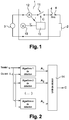
- An electrical circuit is generically represented on the figure 1 .
- Such a circuit comprises a load 2 supplied by an AC power source 3 via an electrical switching device 1.
- a fault of the electric circuit capable of generating an electric arc is symbolized by two keys 4 apart and facing each other.
- the power source 3 delivers a periodic current according to a supply period.
- the switching device 1 comprises a detection circuit 10 able to drive a switch 11 on at least one branch of the electrical circuit, means for measuring the current 12 flowing in the circuit delivering a current signal I to the detection circuit 10 and means for measuring the voltage 13 delivering a voltage signal U to the detection circuit 10.
- the detection circuit 10 implements an electric arc detection method and controls the opening of the electric circuit by switch 11 if it is determined that a potentially dangerous fault has been detected.
- the detection circuit 10 can also perform more conventional functions of overcurrent protection or remote control. These functions are not detailed in the rest of the document.
- the detection circuit 10 implements several detection algorithms 1 to n, in order to detect several types of electric arcs and to make the detection more reliable. As shown in figure 2 each algorithm receives at least one of the measured signals (I, U), analyzes them and then transmits an alert signal A1 to An to a decision unit 14. The decision unit 14 performs a synthesis of the signals of A1 to An and determines a cut-off control signal C for the switch 11.
- an input signal is measured, in this case the current signal I, and an A1 warning signal is given indicating that an electric arc occurs when the input signal is constant over at least a portion of the feed period.
- the current is characterized by a first phase P1 in which the fault is an opening of the circuit and prevents the current from circulating.
- a first phase P1 in which the fault is an opening of the circuit and prevents the current from circulating.
- an arc is established at the level of the fault and the current passes through the arc returning to a level corresponding substantially to what it would be in the absence of defect.
- the first phase P1 therefore corresponds to a phase during which the current is constant.
- the detection of this phase P1 makes it possible to characterize the presence of a defect generating an arc in the circuit.
- the voltage U follows the sinusoidal supply voltage in the first phase P1.
- the measured voltage U is essentially determined by the maintenance voltage of the arc and therefore appears substantially constant.
- the detection of this phase P2 of constant voltage makes it possible to characterize the presence of a defect generating an arc in the circuit.
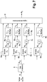
- the detection circuit 10 comprises a frequency memory 101 for storing the frequencies of the levels, a first-in-first-out memory 102, addition means 103, subtraction means 104 and a clock 105.
- the frequency memory 101 comprises registers and a first address bus Addr1 receiving a sampled value of the input signal S according to predetermined levels.
- the addition means 103 are arranged to increment by 1 the register pointed by the value supplied on the first address bus Addr1 among the set of registers.
- the first-in-first-out memory 102 receives the sampled value of the input signal S on an input 1020 and provides an offset value D on an output 1021.
- the frequency memory 101 has a second address bus Addr2 receiving the offset value D from the output 1021 of the first-in-first-out memory 102.
- the subtraction means 104 are arranged to decrement by 1 the register pointed by the offset value D on the second address bus Addr2.
- the addition carried out by the addition means 103, the subtraction carried out by the subtraction means 104 and the offset in the first-in-first-out memory 102 are performed in the same time cycle determined by a clock signal CLK provided by the clock 105.
- each register of the frequency memory 101 is scanned and the frequency of each level corresponding to a predetermined warning threshold, and it delivers the alert signal A1 if the frequency of at least one of the levels is greater than the alert threshold.
- the clock 105 operates at a predetermined frequency and delivers the clock signal CLK with a constant cycle time.
- the value of the signal as sampled is presented at the input of the first-in-first-out memory 102 and is stored in said memory.
- the value is moved with each cycle in the memory and is presented on the output of the first-in-first-out memory 102 after the number of cycles corresponding to the number of registers of the first-in-first-out memory 102, ie after an offset time corresponding to the product of the duration of the clock cycle and the said number of registers.
- the same register is decremented by the subtraction means 104 after the offset time. It therefore no longer influences the content of the frequency memory 101.
- the content of the frequency memory 101 corresponds to the analysis of the signal only over a predetermined time window, of the offset time. This offset time is preferably chosen to be less than a feed period.
- the signal is sampled for example on 8 bits, which corresponds to a frequency memory 101 of 256 registers.
- a second algorithm implements for example a detection by spectral analysis.
- the principle of detection by spectral analysis is based on the composition of the frequency content of the electric arc signals.
- B fo AT fo - m ⁇ f 2 ⁇ + AT fo 2 + AT fo + m ⁇ f 2 ⁇
- Af0 is the sampled signal
- Bf0 is the frequency analysis signal.
- the frequency difference m ⁇ f represents the difference between two near frequencies and depends on the resolution ⁇ f used for the analysis.
- the coefficient ⁇ is greater than 1 and must be calculated so that Bf0 is, on the one hand, continuously increasing between 0 and f0, and on the other hand, continually decreasing between f0 and infinity. When this condition is met, we obtain the curve of the figure 5 .
- FIG. figure 6 The ideal template of the filter 5 is shown on FIG. figure 6 .
- the filtered signal B S supplied by the filter 5 is sent at the input of a series of frequency detectors 6a, 6b, 6c ... 6n, each detector being dedicated to one of the frequencies in odd harmonic with respect to a fundamental f 0.
- Each detector 6a, 6b, 6c ... 6n applies the analysis according to the figure 5 .
- Hn supplied by each of the detectors 6a, 6b, 6c ... 6n, is sent to a summator 7a, 7b, 7c ... 7n summing over a sliding time window. .
- the sum is transmitted to a comparator 8a, 8b, 8c ... 8n which performs a thresholding and which delivers a threshold signal Ja, Jb, Jc ... Jn, in two states, by switching from one state to the next. other when the sum exceeds a predetermined value.
- the threshold signals Ja, Jb, Jc ... Jn and the detection signals Ha, Hb, Hc ... Hn are transmitted to a synthesis unit 9 which delivers an alert signal according to the set of threshold signals and detection signals.
- the presence of an arc is characterized by random variations, and therefore by the absence of a dominant.
- the synthesis unit 9 verifies that the harmonics are almost all present long enough to deliver an alert signal A2 indicating the presence of an arc.
- a third algorithm implements an interpolator filter detection. This detection method is based on the oversampling of the signals. It is part of temporal prediction methods. It is, more exactly, an interpolation method that is used to make a prediction of the signal. The error signal is then calculated by taking the difference between the actual signal and the predicted signal. The presence of an arc fault is often characterized by a sudden change in the signal (either a voltage drop or a rise in current) that induces the appearance of a gap. When the gap is too large, an alarm signal A3 is triggered. This method is based on the Lagrange interpolation equations. It is described in detail in document [2] in paragraph III.
- a fourth algorithm implements a temporal differentiation method.
- E t S t - S t - T where T is a multiple of the period of the input signal S and t is the time.
- T is a multiple of the period of the input signal S
- t is the time.
- the input signal S is regular in its period, and the gap from one period to another is zero.
- the successive periods are not alike, and the difference is no longer zero, which makes it possible to generate an alert signal A4.
- the decision unit 14 takes into account all the warning signals delivered by the different algorithms for determining the cutoff control signal C.
- the determination of the cutoff command C takes into account the average intensity of the current signal I during the alert, the frequency of the warning signals and their average duration.
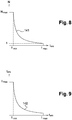
- the Figures 8 and 9 show diagrams representing a first and a second limit curve as a function of the duration of the warning signal and respectively the frequency of the arc and the intensity of the arc.
- the first curve 141 on the figure 8 , is of decreasing hyperbolic form, limited to a limit arc duration t max and a limit arc frequency N max .
- the cutoff is controlled if the frequency pair N of the warning signals and the average duration t arc of the warning signals is beyond the first curve 141.
- the second curve 142 is of decreasing hyperbolic form, limited to the limit arc duration t max and to an arc intensity limit I max .
- the cut is controlled if the alert intensity pair and the average duration t arc is beyond the second curve 142.
Landscapes
- Physics & Mathematics (AREA)
- General Physics & Mathematics (AREA)
- Emergency Protection Circuit Devices (AREA)
- Testing Relating To Insulation (AREA)
- Testing Of Short-Circuits, Discontinuities, Leakage, Or Incorrect Line Connections (AREA)
- Measurement Of Current Or Voltage (AREA)
Claims (7)
- Verfahren zur Erfassung eines elektrischen Lichtbogens in einem elektrischen Schaltkreis, der gemäß einer Versorgungsperiode mit Wechselstrom versorgt wird, gemäß dem mindestens ein Eingangssignal (S) von einem Strom (I) und einer Spannung (U) der Versorgung des elektrischen Schaltkreises gemessen und ein Warnsignal (A1) bereitgestellt wird, das anzeigt, dass ein elektrischer Lichtbogen entsteht, wenn das Eingangssignal (S) über mindestens einen Teil der Versorgungsperiode konstant ist, dadurch gekennzeichnet, dass das Eingangssignal (S) bei seiner Messung gemäß vorbestimmten Niveaus digital gesampelt und, um festzustellen, dass das Eingangssignal (S) konstant ist, die Frequenz bestimmt wird, bei der jedes Niveau des Eingangssignals (S) in einem vorbestimmten temporären Fenster erreicht, die Frequenz jedes Niveaus mit einer vorbestimmten Warnstufe verglichen und das Warnsignal ausgegeben wird, wenn die Frequenz von mindestens einem der Niveaus über der Warnstufe liegt.
- Verfahren nach Anspruch 1, wobei verwendet wird:- ein Frequenzspeicher (101), um die Frequenzen der Niveaus zu speichern, wobei der Frequenzspeicher (101) Register und einen ersten Adressbus (Addr1) umfasst, der den gesampelten Wert des Eingangssignals (S) empfängt,- Additionsmittel (103), um eines der durch den in dem ersten Adressbus (Addr1) bereitgestellten Wert angesprochene Register um 1 zu inkrementieren,- einen First-in-first-out-Speicher (102), der den gesampelten Wert des Eingangssignals (S) über einen Eingang (1020) empfängt und einen versetzten Wert (D) über einen Ausgang (1021) bereitstellt, wobei ein zweiter Adressbus (Addr2) des Frequenzspeichers (101) den versetzten Wert (D) empfängt, und- Subtraktionsmittel (104), um das durch den in dem zweiten Adressbus (Addr2) versetzten Wert angesprochene Register um 1 zu dekrementieren, wobei die Addition, die Subtraktion und der Versatz in dem First-in-first-out-Speicher (102) in einem selben Zyklus durchgeführt werden.
- Verfahren nach einem der vorangehenden Ansprüche, wobei weitere Warnsignale (A2, A3, A4) gemäß mindestens einem anderen Verfahren aus einer Erfassung durch Spektralanalyse, einer Erfassung durch interpolierenden Filter, einer Methode der temporären Differenzierung erstellt und diese Warnsignale (A2, A3, A4) kombiniert werden, um einen Unterbrechungsbefehl (C) des elektrischen Schaltkreises zu bestimmen.
- Verfahren nach Anspruch 3, wobei das Eingangssignal (S) das Stromsignal (I) ist, wobei die Bestimmung des Unterbrechungsbefehls (C) die Stärke des Stromsignals (I) während der Warnung, die Frequenz der Warnsignale (N) und ihre durchschnittliche Dauer (tarc) berücksichtigt.
- Verfahren nach Anspruch 4, wobei die Trennung befohlen wird, wenn sich ein Paar Frequenz (N) der Warnsignale und durchschnittliche Dauer (tarc) der Warnsignale jenseits einer ersten Kurve (141) mit abnehmender hyperbolischer Form befindet oder wenn sich ein Paar Stärke der Warnung und durchschnittliche Dauer jenseits einer zweiten Kurve (142) abnehmender hyperbolischer Form befindet.
- Erfassungsschaltkreis zwecks Erfassung der Anwesenheit eines elektrischen Lichtbogens in einem elektrischen Schaltkreis, der gemäß einer Versorgungsperiode mit Wechselstrom versorgt wird, wobei der Erfassungsschaltkreis (10) Messmittel (12, 13) umfasst, um mindestens ein Eingangssignal (S) von einem Spannungssignal (U) und einem Stromsignal (I) zu ermitteln, das jeweils für die Spannung (U) und die Stromstärke (I) repräsentativ ist, welche den elektrischen Schaltkreis versorgen, wobei der Erfassungsschaltkreis (10) ausgebildet ist, um ein Warnsignal (A1) auszugeben, das anzeigt, dass ein elektrischer Lichtbogen entsteht, wenn das Eingangssignal (S) über mindestens einen Teil der Versorgungsperiode konstant ist, wobei der Schaltkreis dadurch gekennzeichnet ist, dass er Sampelmittel aufweist, um das Eingangssignal (S) bei seiner Messung gemäß vorbestimmten Niveaus digital zu sampeln und Verarbeitungsmittel, um festzustellen, dass das Eingangssignal (S) konstant ist, durch Bestimmen der Frequenz, zu der jedes Niveau von dem Eingangssignal (S) in einem vorbestimmten temporären Fenster erreicht wird, durch Vergleichen der Frequenz jedes Niveaus mit einer vorbestimmten Warnstufe und durch Ausgeben des Warnsignals, wenn die Frequenz von mindestens einem der Niveaus über der Warnstufe liegt.
- Elektrische Umschaltvorrichtung, aufweisend Umschaltmittel (11) zum Öffnen und Schließen eines elektrischen Schaltkreises, der gemäß einer Versorgungsperiode mit Wechselstrom versorgt wird, und eines Erfassungsschaltkreises (10), um die Umschaltmittel (11) zu steuern, dadurch gekennzeichnet, dass der Erfassungsschaltkreis (10) Anspruch 6 entspricht.
Applications Claiming Priority (2)
| Application Number | Priority Date | Filing Date | Title |
|---|---|---|---|
| FR1450817A FR3017256B1 (fr) | 2014-02-03 | 2014-02-03 | Procede et circuit de detection d'un arc electrique dans un circuit, et dispositif de commutation utilisant un tel circuit. |
| PCT/EP2015/052110 WO2015114151A1 (fr) | 2014-02-03 | 2015-02-03 | Procédé et circuit de détection d'un arc électrique dans un circuit, et dispositif de commutation utilisant un tel circuit |
Publications (2)
| Publication Number | Publication Date |
|---|---|
| EP3103178A1 EP3103178A1 (de) | 2016-12-14 |
| EP3103178B1 true EP3103178B1 (de) | 2017-10-11 |
Family
ID=50290191
Family Applications (1)
| Application Number | Title | Priority Date | Filing Date |
|---|---|---|---|
| EP15702470.4A Active EP3103178B1 (de) | 2014-02-03 | 2015-02-03 | Verfahren und schaltung zur erfassung eines elektrischen lichtbogens in einer schaltung und schaltvorrichtung mit solch einer schaltung |
Country Status (7)
| Country | Link |
|---|---|
| US (1) | US10211618B2 (de) |
| EP (1) | EP3103178B1 (de) |
| BR (1) | BR112016017844B1 (de) |
| CA (1) | CA2938695C (de) |
| ES (1) | ES2655897T3 (de) |
| FR (1) | FR3017256B1 (de) |
| WO (1) | WO2015114151A1 (de) |
Families Citing this family (4)
| Publication number | Priority date | Publication date | Assignee | Title |
|---|---|---|---|---|
| JP6332126B2 (ja) * | 2015-04-20 | 2018-05-30 | 株式会社オートネットワーク技術研究所 | 車載負荷制御装置及びコンピュータプログラム |
| WO2017207029A1 (de) * | 2016-05-31 | 2017-12-07 | Siemens Aktiengesellschaft | Störlichtbogenerkennungseinheit |
| FR3112651B1 (fr) * | 2020-07-20 | 2023-05-12 | Schneider Electric Ind Sas | Procédés pour estimer une propriété d’un appareil de commutation électrique, dispositifs pour mettre en œuvre ces procédés |
| US11641099B2 (en) * | 2020-12-30 | 2023-05-02 | The Sloan Company | Arc detection system |
Family Cites Families (15)
| Publication number | Priority date | Publication date | Assignee | Title |
|---|---|---|---|---|
| US5452223A (en) * | 1993-08-20 | 1995-09-19 | Eaton Corporation | Arc detection using current variation |
| IL135120A0 (en) * | 2000-03-16 | 2001-05-20 | Sapir Michael | Apparatus for the detection and early warning of electrical arcing fault |
| US6504692B1 (en) * | 2000-04-06 | 2003-01-07 | Pass & Seymour, Inc. | AFCI device which detects upstream and downstream series and parallel ARC faults |
| US6859042B2 (en) * | 2002-06-07 | 2005-02-22 | Hendry Mechanical Works | Arc detection by non-causal signal correlation |
| US7253640B2 (en) * | 2003-01-13 | 2007-08-07 | Eaton Corporation | Arc fault detector and method for locating an arc fault |
| US7061252B2 (en) * | 2004-07-02 | 2006-06-13 | Hudson Respiratory Care, Inc. | Electrical arcing protection circuit |
| US7441173B2 (en) * | 2006-02-16 | 2008-10-21 | Siemens Energy & Automation, Inc. | Systems, devices, and methods for arc fault detection |
| FR2899718B1 (fr) | 2006-04-11 | 2008-05-23 | Crouzet Automatismes Soc Par A | Dispositif de detection d'arc electrique, dispositif de coupure comportant un tel dispositif et procede de detection d'arc electrique |
| US7451012B2 (en) * | 2007-02-21 | 2008-11-11 | Gree Electric Applicances Inc. Of Zhuhai | Fault electric arc protection circuits and method for detecting fault electric arc |
| US7898781B2 (en) * | 2008-08-01 | 2011-03-01 | Sensata Technologies Massachusetts, Inc. | Arc fault detection apparatus employing a comparator with a continuously variable threshold |
| US8213138B2 (en) * | 2008-08-08 | 2012-07-03 | General Electric Company | Circuit breaker with arc fault detection and method of operation |
| US8743513B2 (en) * | 2010-06-03 | 2014-06-03 | Shakira Limited | Arc fault detector for AC or DC installations |
| US20120275071A1 (en) * | 2011-04-28 | 2012-11-01 | Texas Instruments Incorporated | Arc-fault detection |
| KR101993746B1 (ko) * | 2012-09-10 | 2019-09-30 | 삼성전자주식회사 | 아크 결함 검출 장치, 그를 가지는 전기기기 및 그 제어 방법 |
| US9025287B2 (en) * | 2012-12-19 | 2015-05-05 | Stmicroelectronics S.R.L. | Arc fault detection equipment and method using low frequency harmonic current analysis |
-
2014
- 2014-02-03 FR FR1450817A patent/FR3017256B1/fr not_active Expired - Fee Related
-
2015
- 2015-02-03 ES ES15702470.4T patent/ES2655897T3/es active Active
- 2015-02-03 WO PCT/EP2015/052110 patent/WO2015114151A1/fr not_active Ceased
- 2015-02-03 EP EP15702470.4A patent/EP3103178B1/de active Active
- 2015-02-03 US US15/116,044 patent/US10211618B2/en active Active
- 2015-02-03 CA CA2938695A patent/CA2938695C/fr active Active
- 2015-02-03 BR BR112016017844-0A patent/BR112016017844B1/pt active IP Right Grant
Non-Patent Citations (1)
| Title |
|---|
| None * |
Also Published As
| Publication number | Publication date |
|---|---|
| BR112016017844A2 (de) | 2017-08-08 |
| ES2655897T3 (es) | 2018-02-22 |
| US20170170644A1 (en) | 2017-06-15 |
| WO2015114151A1 (fr) | 2015-08-06 |
| EP3103178A1 (de) | 2016-12-14 |
| BR112016017844B1 (pt) | 2022-02-15 |
| CA2938695C (fr) | 2021-01-12 |
| FR3017256A1 (fr) | 2015-08-07 |
| FR3017256B1 (fr) | 2017-08-11 |
| CA2938695A1 (fr) | 2015-08-06 |
| US10211618B2 (en) | 2019-02-19 |
Similar Documents
| Publication | Publication Date | Title |
|---|---|---|
| EP3103178B1 (de) | Verfahren und schaltung zur erfassung eines elektrischen lichtbogens in einer schaltung und schaltvorrichtung mit solch einer schaltung | |
| EP2383856B1 (de) | Identifizierung und richtungserfassung eines defekts in einem dreiphasennetz | |
| FR2878380A1 (fr) | Procede et dispositif pour l'identification d'arcs electriques de courant de defaut dans des circuits electriques | |
| EP2820433B1 (de) | Elektrizitätszähler und verfahren zur feststellung des zustandes eines schutzschalters einer mit diesem zähler verbundenen vorrichtung | |
| EP1845599A1 (de) | Vorrichtung zur Erfassung eines Lichtbogens, eine solche Vorrichtung umfassende Abschaltvorrichtung und Verfahren zur Erfassung eines Lichtbogens | |
| EP3384592B1 (de) | Verfahren und vorrichtung zur erkennung von lichtbögen in einer fotovoltaikanlage | |
| FR3032804A1 (fr) | Procede de caracterisation d'un defaut non franc dans un cable | |
| EP2927928B1 (de) | Verfahren zur bestimmung einer überhitzung mindestens einer verbindungsklemme einer elektrischen vorrichtung, entsprechendes hilfsgerät und elektrisches system, das eine solche elektrische vorrichtung und ein solches hilfsgerät umfasst | |
| EP3098830B1 (de) | Überwachungsvorrichtung der teilentladungen eines stromnetzes | |
| EP2756592B1 (de) | Verfahren zum steuern eines gesteuerten schalters der die versorgung eines elektrischen motors schaltet | |
| FR3044490A1 (fr) | Procede et dispositif d'evaluation de l'energie produite par un arc electrique dans une installation photovoltaique | |
| EP2937987B1 (de) | Steuerverfahren und -vorrichtung für progressives anlasssystem eines motors, das ein mass der stromvariante nutzt | |
| EP3033760B1 (de) | Verfahren, vorrichtung und computerprogramm zum steuern eines mechatronischen schutzschalters | |
| EP3026447B1 (de) | Verfahren und vorrichtung zur bestimmung einer elektrischen scheinleistung, die von einer elektrischen anlage verbraucht wird | |
| EP0617292B1 (de) | System zur ständigen Überwachung der elektrischen Leitfähigkeit eines Wechselstromnetzes | |
| FR3044488A1 (fr) | Procede et dispositif d'evaluation de l'energie produite par un arc electrique dans une installation photovoltaique | |
| EP2980941A1 (de) | Vorrichtung zum anpassen eines elektrischen stromversorgungssignals, entsprechendes stromversorgungssystem und verfahren zur anpassung des stromversorgungssignals | |
| FR3046677B1 (fr) | Capteur, systeme et procede de detection de variation d'une capacite d'un condensateur de mesure | |
| EP2796885B1 (de) | Verfahren und Vorrichtung zur Bestimmung einer elektrischen Energie, die von einer elektrischen Anlage verbraucht wird | |
| EP1083644B1 (de) | Lichtbogenstromsensitiver Erdfehlerschutz, Auslöser und Schutzschalter mit einer solchen Vorrichtung | |
| FR3031232A1 (fr) | Dispositif et procede de commande d'un relais electromecanique |
Legal Events
| Date | Code | Title | Description |
|---|---|---|---|
| PUAI | Public reference made under article 153(3) epc to a published international application that has entered the european phase |
Free format text: ORIGINAL CODE: 0009012 |
|
| 17P | Request for examination filed |
Effective date: 20160727 |
|
| AK | Designated contracting states |
Kind code of ref document: A1 Designated state(s): AL AT BE BG CH CY CZ DE DK EE ES FI FR GB GR HR HU IE IS IT LI LT LU LV MC MK MT NL NO PL PT RO RS SE SI SK SM TR |
|
| AX | Request for extension of the european patent |
Extension state: BA ME |
|
| RIN1 | Information on inventor provided before grant (corrected) |
Inventor name: WEBER, SERGE Inventor name: BOURNAT, MARC Inventor name: TISSERAND, ETIENNE Inventor name: ANDREA, JONATHAN Inventor name: SCHWEITZER, PATRICK |
|
| DAX | Request for extension of the european patent (deleted) | ||
| GRAP | Despatch of communication of intention to grant a patent |
Free format text: ORIGINAL CODE: EPIDOSNIGR1 |
|
| INTG | Intention to grant announced |
Effective date: 20170613 |
|
| GRAS | Grant fee paid |
Free format text: ORIGINAL CODE: EPIDOSNIGR3 |
|
| GRAA | (expected) grant |
Free format text: ORIGINAL CODE: 0009210 |
|
| AK | Designated contracting states |
Kind code of ref document: B1 Designated state(s): AL AT BE BG CH CY CZ DE DK EE ES FI FR GB GR HR HU IE IS IT LI LT LU LV MC MK MT NL NO PL PT RO RS SE SI SK SM TR |
|
| REG | Reference to a national code |
Ref country code: GB Ref legal event code: FG4D Free format text: NOT ENGLISH |
|
| REG | Reference to a national code |
Ref country code: CH Ref legal event code: EP |
|
| REG | Reference to a national code |
Ref country code: IE Ref legal event code: FG4D Free format text: LANGUAGE OF EP DOCUMENT: FRENCH |
|
| REG | Reference to a national code |
Ref country code: AT Ref legal event code: REF Ref document number: 936815 Country of ref document: AT Kind code of ref document: T Effective date: 20171115 |
|
| REG | Reference to a national code |
Ref country code: DE Ref legal event code: R096 Ref document number: 602015005320 Country of ref document: DE |
|
| REG | Reference to a national code |
Ref country code: FR Ref legal event code: PLFP Year of fee payment: 4 |
|
| REG | Reference to a national code |
Ref country code: CH Ref legal event code: NV Representative=s name: NOVAGRAAF INTERNATIONAL SA, CH |
|
| REG | Reference to a national code |
Ref country code: NL Ref legal event code: MP Effective date: 20171011 |
|
| REG | Reference to a national code |
Ref country code: ES Ref legal event code: FG2A Ref document number: 2655897 Country of ref document: ES Kind code of ref document: T3 Effective date: 20180222 |
|
| REG | Reference to a national code |
Ref country code: LT Ref legal event code: MG4D |
|
| REG | Reference to a national code |
Ref country code: AT Ref legal event code: MK05 Ref document number: 936815 Country of ref document: AT Kind code of ref document: T Effective date: 20171011 |
|
| PG25 | Lapsed in a contracting state [announced via postgrant information from national office to epo] |
Ref country code: NL Free format text: LAPSE BECAUSE OF FAILURE TO SUBMIT A TRANSLATION OF THE DESCRIPTION OR TO PAY THE FEE WITHIN THE PRESCRIBED TIME-LIMIT Effective date: 20171011 |
|
| PG25 | Lapsed in a contracting state [announced via postgrant information from national office to epo] |
Ref country code: SE Free format text: LAPSE BECAUSE OF FAILURE TO SUBMIT A TRANSLATION OF THE DESCRIPTION OR TO PAY THE FEE WITHIN THE PRESCRIBED TIME-LIMIT Effective date: 20171011 Ref country code: FI Free format text: LAPSE BECAUSE OF FAILURE TO SUBMIT A TRANSLATION OF THE DESCRIPTION OR TO PAY THE FEE WITHIN THE PRESCRIBED TIME-LIMIT Effective date: 20171011 Ref country code: LT Free format text: LAPSE BECAUSE OF FAILURE TO SUBMIT A TRANSLATION OF THE DESCRIPTION OR TO PAY THE FEE WITHIN THE PRESCRIBED TIME-LIMIT Effective date: 20171011 Ref country code: NO Free format text: LAPSE BECAUSE OF FAILURE TO SUBMIT A TRANSLATION OF THE DESCRIPTION OR TO PAY THE FEE WITHIN THE PRESCRIBED TIME-LIMIT Effective date: 20180111 |
|
| PG25 | Lapsed in a contracting state [announced via postgrant information from national office to epo] |
Ref country code: HR Free format text: LAPSE BECAUSE OF FAILURE TO SUBMIT A TRANSLATION OF THE DESCRIPTION OR TO PAY THE FEE WITHIN THE PRESCRIBED TIME-LIMIT Effective date: 20171011 Ref country code: BG Free format text: LAPSE BECAUSE OF FAILURE TO SUBMIT A TRANSLATION OF THE DESCRIPTION OR TO PAY THE FEE WITHIN THE PRESCRIBED TIME-LIMIT Effective date: 20180111 Ref country code: IS Free format text: LAPSE BECAUSE OF FAILURE TO SUBMIT A TRANSLATION OF THE DESCRIPTION OR TO PAY THE FEE WITHIN THE PRESCRIBED TIME-LIMIT Effective date: 20180211 Ref country code: GR Free format text: LAPSE BECAUSE OF FAILURE TO SUBMIT A TRANSLATION OF THE DESCRIPTION OR TO PAY THE FEE WITHIN THE PRESCRIBED TIME-LIMIT Effective date: 20180112 Ref country code: AT Free format text: LAPSE BECAUSE OF FAILURE TO SUBMIT A TRANSLATION OF THE DESCRIPTION OR TO PAY THE FEE WITHIN THE PRESCRIBED TIME-LIMIT Effective date: 20171011 Ref country code: RS Free format text: LAPSE BECAUSE OF FAILURE TO SUBMIT A TRANSLATION OF THE DESCRIPTION OR TO PAY THE FEE WITHIN THE PRESCRIBED TIME-LIMIT Effective date: 20171011 Ref country code: LV Free format text: LAPSE BECAUSE OF FAILURE TO SUBMIT A TRANSLATION OF THE DESCRIPTION OR TO PAY THE FEE WITHIN THE PRESCRIBED TIME-LIMIT Effective date: 20171011 |
|
| REG | Reference to a national code |
Ref country code: DE Ref legal event code: R097 Ref document number: 602015005320 Country of ref document: DE |
|
| PG25 | Lapsed in a contracting state [announced via postgrant information from national office to epo] |
Ref country code: CZ Free format text: LAPSE BECAUSE OF FAILURE TO SUBMIT A TRANSLATION OF THE DESCRIPTION OR TO PAY THE FEE WITHIN THE PRESCRIBED TIME-LIMIT Effective date: 20171011 Ref country code: SK Free format text: LAPSE BECAUSE OF FAILURE TO SUBMIT A TRANSLATION OF THE DESCRIPTION OR TO PAY THE FEE WITHIN THE PRESCRIBED TIME-LIMIT Effective date: 20171011 Ref country code: DK Free format text: LAPSE BECAUSE OF FAILURE TO SUBMIT A TRANSLATION OF THE DESCRIPTION OR TO PAY THE FEE WITHIN THE PRESCRIBED TIME-LIMIT Effective date: 20171011 Ref country code: EE Free format text: LAPSE BECAUSE OF FAILURE TO SUBMIT A TRANSLATION OF THE DESCRIPTION OR TO PAY THE FEE WITHIN THE PRESCRIBED TIME-LIMIT Effective date: 20171011 |
|
| PLBE | No opposition filed within time limit |
Free format text: ORIGINAL CODE: 0009261 |
|
| STAA | Information on the status of an ep patent application or granted ep patent |
Free format text: STATUS: NO OPPOSITION FILED WITHIN TIME LIMIT |
|
| PG25 | Lapsed in a contracting state [announced via postgrant information from national office to epo] |
Ref country code: SM Free format text: LAPSE BECAUSE OF FAILURE TO SUBMIT A TRANSLATION OF THE DESCRIPTION OR TO PAY THE FEE WITHIN THE PRESCRIBED TIME-LIMIT Effective date: 20171011 Ref country code: PL Free format text: LAPSE BECAUSE OF FAILURE TO SUBMIT A TRANSLATION OF THE DESCRIPTION OR TO PAY THE FEE WITHIN THE PRESCRIBED TIME-LIMIT Effective date: 20171011 |
|
| 26N | No opposition filed |
Effective date: 20180712 |
|
| PG25 | Lapsed in a contracting state [announced via postgrant information from national office to epo] |
Ref country code: MC Free format text: LAPSE BECAUSE OF FAILURE TO SUBMIT A TRANSLATION OF THE DESCRIPTION OR TO PAY THE FEE WITHIN THE PRESCRIBED TIME-LIMIT Effective date: 20171011 Ref country code: MT Free format text: LAPSE BECAUSE OF FAILURE TO SUBMIT A TRANSLATION OF THE DESCRIPTION OR TO PAY THE FEE WITHIN THE PRESCRIBED TIME-LIMIT Effective date: 20171011 |
|
| REG | Reference to a national code |
Ref country code: IE Ref legal event code: MM4A |
|
| REG | Reference to a national code |
Ref country code: BE Ref legal event code: MM Effective date: 20180228 |
|
| PG25 | Lapsed in a contracting state [announced via postgrant information from national office to epo] |
Ref country code: SI Free format text: LAPSE BECAUSE OF FAILURE TO SUBMIT A TRANSLATION OF THE DESCRIPTION OR TO PAY THE FEE WITHIN THE PRESCRIBED TIME-LIMIT Effective date: 20171011 Ref country code: LU Free format text: LAPSE BECAUSE OF NON-PAYMENT OF DUE FEES Effective date: 20180203 |
|
| PG25 | Lapsed in a contracting state [announced via postgrant information from national office to epo] |
Ref country code: IE Free format text: LAPSE BECAUSE OF NON-PAYMENT OF DUE FEES Effective date: 20180203 |
|
| PG25 | Lapsed in a contracting state [announced via postgrant information from national office to epo] |
Ref country code: BE Free format text: LAPSE BECAUSE OF NON-PAYMENT OF DUE FEES Effective date: 20180228 |
|
| PG25 | Lapsed in a contracting state [announced via postgrant information from national office to epo] |
Ref country code: TR Free format text: LAPSE BECAUSE OF FAILURE TO SUBMIT A TRANSLATION OF THE DESCRIPTION OR TO PAY THE FEE WITHIN THE PRESCRIBED TIME-LIMIT Effective date: 20171011 |
|
| PG25 | Lapsed in a contracting state [announced via postgrant information from national office to epo] |
Ref country code: PT Free format text: LAPSE BECAUSE OF FAILURE TO SUBMIT A TRANSLATION OF THE DESCRIPTION OR TO PAY THE FEE WITHIN THE PRESCRIBED TIME-LIMIT Effective date: 20171011 |
|
| PG25 | Lapsed in a contracting state [announced via postgrant information from national office to epo] |
Ref country code: RO Free format text: LAPSE BECAUSE OF FAILURE TO SUBMIT A TRANSLATION OF THE DESCRIPTION OR TO PAY THE FEE WITHIN THE PRESCRIBED TIME-LIMIT Effective date: 20171011 Ref country code: HU Free format text: LAPSE BECAUSE OF FAILURE TO SUBMIT A TRANSLATION OF THE DESCRIPTION OR TO PAY THE FEE WITHIN THE PRESCRIBED TIME-LIMIT; INVALID AB INITIO Effective date: 20150203 Ref country code: CY Free format text: LAPSE BECAUSE OF FAILURE TO SUBMIT A TRANSLATION OF THE DESCRIPTION OR TO PAY THE FEE WITHIN THE PRESCRIBED TIME-LIMIT Effective date: 20171011 Ref country code: MK Free format text: LAPSE BECAUSE OF NON-PAYMENT OF DUE FEES Effective date: 20171011 |
|
| PG25 | Lapsed in a contracting state [announced via postgrant information from national office to epo] |
Ref country code: AL Free format text: LAPSE BECAUSE OF FAILURE TO SUBMIT A TRANSLATION OF THE DESCRIPTION OR TO PAY THE FEE WITHIN THE PRESCRIBED TIME-LIMIT Effective date: 20171011 |
|
| REG | Reference to a national code |
Ref country code: CH Ref legal event code: U11 Free format text: ST27 STATUS EVENT CODE: U-0-0-U10-U11 (AS PROVIDED BY THE NATIONAL OFFICE) Effective date: 20260301 |
|
| PGFP | Annual fee paid to national office [announced via postgrant information from national office to epo] |
Ref country code: GB Payment date: 20260218 Year of fee payment: 12 |
|
| PGFP | Annual fee paid to national office [announced via postgrant information from national office to epo] |
Ref country code: ES Payment date: 20260319 Year of fee payment: 12 |
|
| PGFP | Annual fee paid to national office [announced via postgrant information from national office to epo] |
Ref country code: DE Payment date: 20260217 Year of fee payment: 12 |
|
| PGFP | Annual fee paid to national office [announced via postgrant information from national office to epo] |
Ref country code: IT Payment date: 20260227 Year of fee payment: 12 |
|
| PGFP | Annual fee paid to national office [announced via postgrant information from national office to epo] |
Ref country code: FR Payment date: 20260219 Year of fee payment: 12 |
|
| PGFP | Annual fee paid to national office [announced via postgrant information from national office to epo] |
Ref country code: CH Payment date: 20260301 Year of fee payment: 12 |