EP3103189B1 - Mehrstufiger wechselrichter und betriebsverfahren - Google Patents
Mehrstufiger wechselrichter und betriebsverfahren Download PDFInfo
- Publication number
- EP3103189B1 EP3103189B1 EP15765595.2A EP15765595A EP3103189B1 EP 3103189 B1 EP3103189 B1 EP 3103189B1 EP 15765595 A EP15765595 A EP 15765595A EP 3103189 B1 EP3103189 B1 EP 3103189B1
- Authority
- EP
- European Patent Office
- Prior art keywords
- switch
- output
- voltage
- source
- output filter
- Prior art date
- Legal status (The legal status is an assumption and is not a legal conclusion. Google has not performed a legal analysis and makes no representation as to the accuracy of the status listed.)
- Active
Links
Images


Classifications
-
- H—ELECTRICITY
- H02—GENERATION; CONVERSION OR DISTRIBUTION OF ELECTRIC POWER
- H02M—APPARATUS FOR CONVERSION BETWEEN AC AND AC, BETWEEN AC AND DC, OR BETWEEN DC AND DC, AND FOR USE WITH MAINS OR SIMILAR POWER SUPPLY SYSTEMS; CONVERSION OF DC OR AC INPUT POWER INTO SURGE OUTPUT POWER; CONTROL OR REGULATION THEREOF
- H02M7/00—Conversion of AC power input into DC power output; Conversion of DC power input into AC power output
- H02M7/42—Conversion of DC power input into AC power output without possibility of reversal
- H02M7/44—Conversion of DC power input into AC power output without possibility of reversal by static converters
- H02M7/48—Conversion of DC power input into AC power output without possibility of reversal by static converters using discharge tubes with control electrode or semiconductor devices with control electrode
- H02M7/483—Converters with outputs that each can have more than two voltages levels
- H02M7/487—Neutral point clamped inverters
Definitions
- the present invention relates to a multilevel inverter device and method.
- renewable energy sources include solar energy, wind power, tidal wave energy and the like.
- a solar power conversion system may include a plurality of solar panels connected in series or in parallel. The output of the solar panels may generate a variable dc voltage depending on a variety of factors such as time of day, location and sun tracking ability. In order to regulate the output of the solar panels, the output of the solar panels may be coupled to a dc/dc converter so as to achieve a regulated output voltage at the output of the dc/dc converter.
- the solar panels may be connected with a backup battery system through a battery charge control apparatus. During the day, the backup battery is charged through the output of the solar panels. When the power utility fails or the solar panels are an off-grid power system, the backup battery provides electricity to the loads coupled to the solar panels.
- a solar inverter is employed to convert the variable dc output of the photovoltaic modules to a 120 volts ac power source.
- a plurality of multilevel inverter topologies may be employed to achieve high power as well as high efficiency conversion from solar energy to utility electricity.
- a high power ac output can be achieved by using a series of power semiconductor switches to convert a plurality of low voltage dc sources to a high power ac output by synthesizing a staircase voltage waveform.
- multilevel inverters may be divided into three categories, namely diode clamped multilevel inverters, flying capacitor multilevel inverters and cascaded H-bridge multilevel inverters. Furthermore, multilevel inverters may employ different pulse width modulation (PWM) techniques such as sinusoidal PWM (SPWM), selective harmonic elimination PWM, space vector modulation and the like. Multilevel inverters are a common power topology for high and medium power applications such as utility interface for renewable power sources, flexible ac transmission systems, medium voltage motor drive systems and the like.
- PWM pulse width modulation
- SPWM sinusoidal PWM
- SPWM selective harmonic elimination PWM
- space vector modulation space vector modulation
- the diode clamped multilevel inverter is commonly referred to as a three-level neutral point clamped (NPC) inverter.
- NPC neutral point clamped
- a three-level NPC inverter requires two series connected capacitors coupled between the input dc buses. Each capacitor is charged to an equal potential.
- the three-level NPC inverter may comprise four switching elements and two clamping diodes. The clamping diodes help to reduce the voltage stress on the switching element to one capacitor voltage level.
- An NPC inverter utilizes a staircase waveform to generate an ac output.
- a staircase waveform resembles a desired sinusoidal waveform.
- the output voltage of the NPC inverter may be of a low total harmonic distortion (THD).
- the staircase waveform may reduce the voltage stresses.
- EMC electromagnetic compatibility
- the NPC inverter may operate at a lower switching frequency. Such a lower switching helps to reduce switching frequency losses so as to achieve an efficient power conversion system.
- WO 2015/131763 A1 describes an inverter comprising a first boost apparatus and a second boost apparatus.
- a first half-cycle switching network is coupled to the first boost apparatus.
- the first half-cycle switching network is configured such that a first three-level conductive path is formed when a voltage at a dc source is greater than an instantaneous value of a voltage at an output of the inverter.
- a first five-level conductive path is formed when the instantaneous value of the voltage at the output of inverter is greater than the voltage at the dc source.
- a first switch is coupled to an input of an L-C filter and the first boost apparatus.
- a second switch is coupled to the input of the L-C filter and the second boost apparatus.
- a third switch is coupled between the positive dc bus and the first switch.
- a fourth switch is coupled between the negative dc bus and the second switch.
- An advantage of an embodiment of the present invention is generating a staircase waveform using a hybrid inverter comprising a three-level inverter structure and a five-level inverter structure. Such a hybrid inverter helps to improve the efficiency, reliability and cost of multilevel inverters.
- the present invention will be described with respect to preferred embodiments in a specific context, namely a five-level inverter.
- the invention may also be applied, however, to a variety of power converters including multilevel rectifiers, multilevel inverters, multilevel ac-to-ac converters and the like.
- the invention may also be applied to a variety of three-phase multilevel inverters.
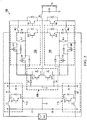
- FIG. 1 illustrates a block diagram of a multilevel inverter in accordance with various embodiments of the present disclosure.
- the multilevel inverter 100 comprises a dc source PV1, a first boost apparatus 112 coupled between a first terminal of the dc source PV1 and ground, a second boost apparatus 114 coupled between a second terminal of the dc source PV1 and ground, a freewheeling apparatus 106, a first converting stage 102 and a second converting stage 104.
- the dc source PV1 shown in Figure 1 may be implemented as a solar panel. More particularly, in some embodiments, while Figure 1 illustrate a single dc source PV1, the dc source PV1 may comprise a plurality of solar panels connected in series, in parallel, any combinations thereof and the like. Two input capacitors C1 and C2 are connected in series. As shown in Figure 1 , the series-connected input capacitors C1 and C2 are coupled to the outputs of the dc source PV1. In some embodiments, the common node of the input capacitors C1 and C2 is connected to ground as shown in Figure 1 .
- the multilevel inverter 100 comprises five voltage levels (e.g., VI, -V1, V2, -V2 and ground).
- a first terminal of the dc source PV1 is of an output voltage V1.
- a second terminal of the dc source PV1 is of an output voltage -V1.
- the first boost apparatus 112 and the second boost apparatus 114 are coupled to the first terminal and second terminal of the dc source PV1 respectively.
- the first boost apparatus 112 and the second boost apparatus 114 convert the output voltages V1 and -V1 of the first terminal and the second terminal of the dc source PV1 to V2 and -V2 respectively as shown in Figure 1 .
- the first boost apparatus 112 and the second boost apparatus 114 may be implemented by using step up circuits such as boost dc/dc converters and/or the like.
- a boost dc/dc converter is formed by an input inductor, a low side switch and a blocking diode. The detailed configuration of the boost dc/dc converter will be described below with respect to Figure 2 .
- Figure 1 illustrates the multilevel inverter 100 with two boost apparatuses (e.g., the first boost apparatus 112 and the second boost apparatus 114), the multilevel inverter 100 could accommodate any number of boost apparatuses.
- the number of boost apparatuses illustrated herein is limited solely for the purpose of clearly illustrating the inventive aspects of the various embodiments.
- the present invention is not limited to any specific number of boost apparatuses.
- additional boost apparatuses may be employed to achieve an output staircase waveform having additional voltage levels.
- the multilevel inverter 100 may further comprise an output filter formed by an inductor Lo and a capacitor Co, and a plurality of switches Q1 and Q2. As shown in Figure 1 , the input of the output filter is coupled to the common node of the switches Q1 and Q2. While Figure 1 shows the switches Q1 and Q2 may be coupled to V2 and -V2 respectively, the switches Q1 and Q2 may be coupled to V1 and -V1 respectively through the first converting stage 102 and the second converting stage 104. The detailed operation principles of the first converting stage 102 and the second converting stage 104 will be described below in detail with respect to Figures 3-8 .
- the switches may be an insulated gate bipolar transistor (IGBT) device.
- the switching element can be any controllable switches such as metal oxide semiconductor field-effect transistor (MOSFET) devices, integrated gate commutated thyristor (IGCT) devices, gate turn-off thyristor (GTO) devices, silicon controlled rectifier (SCR) devices, junction gate field-effect transistor (JFET) devices, MOS controlled thyristor (MCT) devices and the like.
- MOSFET metal oxide semiconductor field-effect transistor
- IGCT integrated gate commutated thyristor
- GTO gate turn-off thyristor
- SCR silicon controlled rectifier
- JFET junction gate field-effect transistor
- MCT MOS controlled thyristor
- the freewheeling apparatus 106 may be coupled between the input of the output filter and ground.
- the first freewheeling route may provide a conductive path for the current flowing in the switches (e.g ., switch Q1) after the switches are turned off.
- the detailed structure of the freewheeling apparatus 106 will be described below with respect to Figure 2 .
- the first converting stage 102 and the second converting stage 104 may comprise a plurality switches. Each switch is configured such that a staircase waveform is generated at the input of the filter by using different combinations of the switches. In some embodiments, a portion of the converting stage may be enabled. The converting stage functions as a three-level inverter structure. In alternative embodiments, depending on the voltage at the outputs of the dc source PV1, another portion of the converting stage may be activated. The converting stage may comprise both a three-level inverter structure and a five-level inverter structure. The detailed operation of the first converting stage 102 and the second converting stage 104 will be described below with respect to Figures 2-8 .
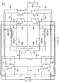
- FIG 2 illustrates a schematic diagram of the multilevel inverter shown in Figure 1 in accordance with various embodiments of the present disclosure.
- the multilevel inverter 100 comprises the first boost apparatus 112 generating an output voltage V2 higher than the input voltage V1 from the dc source PV1.
- the second boost apparatus 114 is employed to generate a negative voltage -V2.
- Both the first boost apparatus 112 and the second boost apparatus 114 are implemented as boost dc/dc converters. For simplicity, only the first boost apparatus 112 will be described in detail below.
- the first boost apparatus 112 is formed by an input inductor LI, a low side switch Q11, a blocking diode D1 and an output capacitor C3.
- a controller (not shown) may control the turn-on duty cycle of the low side switch Q11 so as to regulate the output voltage V2 across the output capacitor C3.
- boost dc/dc converters are well known in the art, and hence are not discussed in further detail to avoid unnecessary repetition.
- boost dc/dc converters are merely an example to implement the first boost apparatus 112 and the second boost apparatus 114.
- Other boost topologies are also within the contemplated scope of the invention.
- a boost dc/dc converter is simply one manner of generating a higher voltage from the dc source (e.g ., V1) and that other and alternate embodiment boost topologies could be employed (such as employing a switched capacitor voltage doubler) and that other circuits, (e.g ., a charge pump voltage doubler, etc.) could be employed for this function.
- the first converting stage 102 comprises switches Q15, Q17 and Q19, relays RL1 and RL3, and diode D5.
- the first converting stage 102 is activated during a first half cycle of the output ac waveform Vo.
- the second converting stage 104 comprises switches Q16, Q18 and Q20, relays RL2 and RL4, and diode D6.
- the second converting stage 104 is activated during a second half cycle of the output ac waveform Vo.
- the first converting stage 102 may function as either a three-level inverter structure or a five-level inverter structure by configuring the switches of the first converting stage 102.
- the first converting stage 102 may enter either a three-level inverter operation mode or a five-level inverter operation mode depending on the voltage of V1. More particularly, in one complete cycle, when V1 is greater than the instantaneous value of Vo, the first converting stage 102 may enter a three-level inverter operation mode. Otherwise, the first converting stage 102 may enter a five-level inverter operation mode.
- Q1 and Q19 are turned off.
- Q13, Q17 and Q15 are turned on.
- RL1 and RL3 are turned off.
- Diode D5 is forward-biased.
- the turned on Q13, Q17 and Q15 form a three-level inverter structure during the first half cycle.
- Q17 is turned off.
- Q1, Q15, Q13 and Q19 are turned on.
- Diode D5 is forward-biased.
- RL1 and RL3 are turned off.
- the first boost apparatus 112 is activated.
- the turned on Q1, Q13, Q15 and Q19 form a five-level inverter structure during the first half cycle.
- the second converting stage 104 may function as either a three-level inverter structure or a five-level inverter structure by configuring the switches of the second converting stage 104. More particularly, in a second half cycle, when the instantaneous value of Vo is greater than -V1, the second converting stage 104 may enter a three-level inverter operation mode. Otherwise, the second converting stage 104 may enter a five-level inverter operation mode.
- Q2 and Q20 are turned off.
- Q14, Q18 and Q16 are turned on.
- RL2 and RL4 are turned off.
- Diode D6 is forward-biased.
- the turned on Q14, Q18 and Q16 form a three-level inverter structure during the second half cycle.
- Q18 is turned off.
- Q2, Q16, Q14 and Q20 are turned on.
- Diode D6 is forward-biased.
- RL2 and RL4 are turned off.
- the second boost apparatus 114 is activated.
- the turned on Q2, Q14, Q16 and Q20 form a five-level inverter structure during the second half cycle.
- the switches Q17, Q18, Q19 and Q20 may be implemented as MOSFETs.
- the switches Q17, Q18, Q19 and Q20 may be implemented as other suitable devices such as IGBT and/or the like.
- the freewheeling apparatus 106 may comprise switches Q13 and Q14, and diodes D3 and D4. As shown in Figure 2 , the diode D3 and the switch Q13 may form a first freewheeling route connected between the input of the output filter and ground. In some embodiments, the first freewheeling route may provide a conductive path for the current flowing in the switch Q1 after Q1 is turned off.
- the diode D4 and the switch Q14 may form a second freewheeling route connected between the input of the output filter and ground.
- the second freewheeling route may provide a conductive path for the current flowing in the switch Q2 after Q2 is turned off.
- the schematic diagram of the freewheeling apparatus 106 described above is merely an exemplary structure and is not meant to limit the current embodiments.
- the diodes D3 and D4 may be replaced by two switches respectively.
- switches Q13 and Q14 may be implemented as IGBT transistors, the switches Q13 and Q14 can be any controllable switches such as MOSFET devices, IGCT devices, GTO devices, SCR devices, JFET devices, MCT devices, any combinations thereof and/or the like.
- the relays RL1, RL2, RL3 and RL4 are included to provide one additional operation mode.
- the input voltage e.g., V1
- the first boost apparatus 112 and the second boost apparatus 114 may be bypassed by turning on the relays RL1, RL2, RL3 and RL4. As such, the total power losses of the multilevel inverter 100 may be reduced.
- FIG 3 illustrates a timing diagram of various signals in the multilevel inverter shown in Figure 2 in accordance with various embodiments of the present disclosure.
- Vo is the voltage waveform at the output of the output filter shown in Figure 2 .
- the output filter is formed by an output inductor Lo and an output capacitor Co.
- the output filter helps to filter the multilevel PWM voltage (voltage at the input of the output filter) to obtain a sinusoidal waveform as shown in Figure 3 .
- the timing diagram can be divided into two portions, namely a first half cycle and a second half cycle.
- the first half cycle starts from t0 and ends at t3.
- the second half cycle starts from t3 and ends at t6.
- the first half cycle can be divided into three portions according to the relationship between V1 and Vo. More particularly, a first portion starts from t0 and ends at t1. In the first portion, V1 is greater than the instantaneous value of Vo. A second portion starts from t1 and ends at t2. In the second portion, the instantaneous value of Vo is greater than V1. A third portion starts from t2 and ends at t3. In the third portion, V1 is greater than the instantaneous value of Vo.
- the operation mode during the first portion and the third portion of the first half cycle may be alternatively referred to as a three-level inverter operation mode of the first half cycle.
- the operation mode during the second portion of the first half cycle is alternatively referred to as a five-level inverter operation mode of the first half cycle.
- the second half cycle can be divided into three portions according to the relationship between V1 and Vo. More particularly, a first portion of the second half cycle starts from t3 and ends at t4. In the first portion of the second half cycle, the instantaneous value of Vo is greater than -V1. A second portion of the second half cycle starts from t4 and ends at t5. In the second portion, -V1 is greater than the instantaneous value of Vo. A third portion of the second half cycle starts from t5 and ends at t6. In the third portion, the instantaneous value of Vo is greater than -V1.
- the operation mode during the first portion and the third portion of the second half cycle may be alternatively referred to as a three-level inverter operation mode of the second half cycle.
- the operation mode during the second portion of the second half cycle is alternatively referred to as a five-level inverter operation mode of the second half cycle.
- the detailed operation principles of each portion will be described below with respect to Figures 4-7 .
- Figure 4 illustrates a schematic diagram of a system configuration of the three-level inverter operation mode of the multilevel inverter shown in Figure 2 in accordance with various embodiments of the present disclosure.
- the multilevel inverter 100 enters a three-level inverter operation mode.
- a first conductive path is enabled as indicated by arrows 402 and 404 shown in Figure 4 .
- the first conductive path is formed by turned on Q13, Q15 and Q17.
- Q15 is coupled between the input of the output filter and the first terminal of the dc source PV1.
- Q13 and Q17 are connected in series and coupled between the input of the output filter and the first terminal of the dc source PV1.
- the current flows from the first terminal of the dc source PV1 to the output filter through two current paths.
- the first current path comprises Q15.
- the second current path comprises Q17 and Q13. As shown in Figure 4 , these two current paths are connected in parallel.
- Q17 of the second current path may help Q15 achieve zero voltage switching. The zero voltage switching process will be described below with respect to Figure 5 .
- the multilevel inverter 100 enters a three-level inverter operation mode.
- a second conductive path is enabled as indicated by arrows 406 and 408 shown in Figure 4 .
- the second conductive path is formed by Q16, Q14 and Q18.
- Q16 is coupled between the input of the output filter and the second terminal of the dc source PV1.
- Q14 and Q18 are connected in series and coupled between the input of the output filter and the second terminal of the dc source PV1.
- the operating principle of the second conductive path is similar to that of the first conductive path described above, and hence is not described in detail herein to avoid repetition.
- FIG. 5 illustrates a timing diagram of various signals in the multilevel inverter shown in Figure 4 in accordance with various embodiments of the present disclosure.
- the multilevel inverter 100 enters a three-level inverter operation mode during the time interval from t0 to t1, the time interval from t2 to t3, the time interval from t3 to t4 and the time interval from t5 to t6.
- the gate drive signals in these four time intervals are similar. For simplicity, only the gate signals in the time interval from t0 to t1 will be described below in detail.
- switch Q17 may be turned off. More particularly, Q17 may be turned off after Q15 has achieved a zero voltage turn-on transition and turned on prior to Q15's turn-off at t8. It should further be noted that Q18 is able to help Q16 achieve zero voltage switching during the second half cycle. The zero voltage switching transition of Q16 is similar to that of Q15, and hence is not discussed in further detail herein to avoid repetition.
- Figure 6 illustrates a schematic diagram of a system configuration of the five-level operation mode of the multilevel inverter shown in Figure 2 in accordance with various embodiments of the present disclosure.
- the multilevel inverter enters a five-level inverter operation mode.
- Two conductive paths are enabled as indicated by arrows 602, 603 and 604 shown in Figure 6 .
- the first conductive path is formed by Q15. As shown in Figure 6 , Q15 is coupled between the input of the output filter and the first terminal of the dc source PV1.
- the second conductive path comprises Q1, Q13 and Q19. Q13 and Q19 are connected in series and coupled between the input of the output filter and the output of the first boost apparatus 112.
- Q1 is coupled between the input of the output filter and the output of the first boost apparatus 112.
- the current may flow from the first terminal of the dc source PV1 to the output filter through Q15. Alternatively, the current flows from the output of the first boost apparatus 112 to the output filter through turned on Q1, Q17 and Q13.
- diode D5 may prevent the current flowing through Q15 when there is a current flowing through the second conductive path. It should further be noted Q19 of the second current path may help Q1 achieve zero voltage switching. The zero voltage switching process of Q1 will be described below with respect to Figure 7 .
- the multilevel inverter 100 enters the five-level inverter operation mode.
- Two conductive paths are enabled as indicated by arrows 606, 607 and 608 shown in Figure 6 .
- the first conductive path is formed by Q16.
- Q16 is coupled between the input of the output filter and the second terminal (-V1) of the dc source PV1.
- the second conductive path comprises Q2, Q14 and Q20.
- Q14 and Q20 are connected in series and coupled between the input of the output filter and the output of the second boost apparatus 114.
- Q1 is coupled between the input of the output filter and the output of the second boost apparatus 114.
- the operating principle of the conductive paths in the second half cycle is similar to that of the first half cycle, and hence is not described in detail herein.
- Figure 7 illustrates a timing diagram of various signals in the multilevel inverter shown in Figure 6 in accordance with various embodiments of the present disclosure.
- the multilevel inverter system enters a five-level inverter operation mode during the time interval from t1 to t2 and the time interval from t4 to t5.
- the gate drive signals in these two time intervals are similar. For simplicity, only the gate signals in the time interval from t1 to t2 will be described below in detail.
- Q19 is turned on at t1 before Q1 is turned on at t11.
- Q13 is always on during this time interval.
- the turned-on Q17 and Q13 are connected in series to form a zero voltage switching auxiliary circuit.
- Q19 may be turned off at t13. In sum, Q19 helps Q1 achieve zero voltage switching.
- switch Q19 may be turned off. More particularly, Q19 may be turned off after Q1 has achieved a zero voltage turn-on transition and turned on again prior to Q1's turn-off at t12. It should further be noted that Q20 is able to help Q2 achieve zero voltage switching during the second half cycle. The zero voltage switching transition of Q2 is similar to that of Q1, and hence is not discussed in further detail herein to avoid repetition.
- FIG 8 illustrates a schematic diagram of another system configuration of the multilevel inverter shown in Figure 2 in accordance with various embodiments of the present disclosure.
- the first boost apparatus 112 and the second boost apparatus 114 are bypassed when a voltage across the dc source PV1 is greater than the peak-to-peak value of Vo.
- the energy is delivered to the output filter through Q1 and Q15.
- the turned on relays RL1 and RL3 create two conductive paths connected in parallel.
- the energy is delivered to the output filter through Q2 and Q16.
- One advantageous feature of having relays RL1, RL2, RL3 and RL4 is the power losses may be reduced by turning off the first boost apparatus 112 and the second boost apparatus 114. As a result, the efficiency as well as the reliability of the multilevel inverter 100 may be improved.
- the first three-level conductive path is formed by Q15 coupled between the input of the output filter and the first terminal of the dc source, and Q13 and Q17 connected in series and coupled between the input of the output filter and the first terminal of the dc source.
- the first five-level conductive path is formed by Q15 coupled between the input of the output filter and the first terminal of the dc source, Q1 coupled between an output of the first boost apparatus and the input of the output filter, and Q13 and Q19 connected in series and coupled between the output of the first boost apparatus and the input of the output filter.
- the second three-level conductive path is formed by Q16 coupled between the input of the output filter and the second terminal of the dc source, and Q14 and Q18 connected in series and coupled between the input of the output filter and the second terminal of the dc source.
- the second five-level conductive path is formed by Q16 coupled between the input of the output filter and the second terminal of the dc source, Q2 coupled between an output of the second boost apparatus and the input of the output filter, and Q14 and Q20 connected in series and coupled between the output of the second boost apparatus and the input of the output filter.
- the first three-level conductive path is formed by a first switch coupled between the input of the output filter and the first terminal of the dc source, and a second switch and a third switch connected in series and coupled between the input of the output filter and the first terminal of the dc source.
- the first five-level conductive path is formed by the first switch coupled between the input of the output filter and the first terminal of the dc source, a fourth switch coupled between an output of the first boost apparatus and the input of the output filter, and the second switch and a fifth switch connected in series and coupled between the output of the first boost apparatus and the input of the output filter.
- the second three-level conductive path is formed by a sixth switch coupled between the input of the output filter and the second terminal of the dc source, and a seventh switch and an eighth switch connected in series and coupled between the input of the output filter and the second terminal of the dc source.
- the second five-level conductive path is formed by the sixth switch coupled between the input of the output filter and the second terminal of the dc source, a ninth switch coupled between an output of the second boost apparatus and the input of the output filter, and the seventh switch and a tenth switch connected in series and coupled between the output of the second boost apparatus and the input of the output filter.
- the first three-level conductive path is formed by Q15 coupled between the first terminal of the dc source and the input of the output filter, and Q13 of the freewheeling apparatus, and wherein Q15 and Q13 are connected in parallel.
- the first five-level conductive path is formed by Q15, Q1 coupled between the output of the first boost apparatus and the input of the output filter, and Q13 of the freewheeling apparatus.
- the second three-level conductive path is formed by Q16 coupled between the second terminal of the dc source and the input of the output filter, and Q14 of the freewheeling apparatus, and wherein the Q14 and Q16 are connected in parallel.
- the second five-level conductive path is formed by Q16, Q2 coupled between the output of the second boost apparatus and the input of the output filter, and Q14 of the freewheeling apparatus.
- the first three-level conductive path is formed by a first switch coupled between the first terminal of the dc source and the input of the output filter, and a second switch of the freewheeling apparatus, and wherein the first switch and the second switch are connected in parallel.
- the first five-level conductive path is formed by the first switch, a third switch coupled between the output of the first boost apparatus and the input of the output filter, and the second switch of the freewheeling apparatus.
- the second three-level conductive path is formed by a fourth switch coupled between the second terminal of the dc source and the input of the output filter, and a fifth switch of the freewheeling apparatus, and wherein the fifth switch and the fourth switch are connected in parallel.
- the second five-level conductive path is formed by the fourth switch, a sixth switch coupled between the output of the second boost apparatus and the input of the output filter, and the fifth switch of the freewheeling apparatus.
- the first three-level conductive path further comprises Q17 connected in series with Q13 of the freewheeling apparatus, and wherein Q17 is configured to be turned on before a turn-on of Q15.
- the first five-level conductive path further comprises Q19 connected in series with Q13 of the freewheeling apparatus, and wherein Q19 is configured to be turned on before a turn-on of Q1.
- the second three-level conductive path further comprises Q18 connected in series with Q14 of the freewheeling apparatus, and wherein Q18 is configured to be turned on before a turn-on of Q16.
- the second five-level conductive path further comprises Q20 connected in series with Q14 of the freewheeling apparatus, and wherein Q20 is configured to be turned on before a turn-on of Q2.
- the first three-level conductive path further comprises a seventh switch connected in series with the second switch of the freewheeling apparatus, and wherein the seventh switch is configured to be turned on before a turn-on of the first switch.
- the first five-level conductive path further comprises an eighth switch connected in series with the second switch of the freewheeling apparatus, and wherein the eighth switch is configured to be turned on before a turn-on of the third switch.
- the second three-level conductive path further comprises a ninth switch connected in series with the fifth switch of the freewheeling apparatus, and wherein the ninth switch is configured to be turned on before a turn-on of the fourth switch.
- the second five-level conductive path further comprises a tenth switch connected in series with the fifth switch of the freewheeling apparatus, and wherein the tenth switch is configured to be turned on before a turn-on of the sixth switch.
Landscapes
- Engineering & Computer Science (AREA)
- Power Engineering (AREA)
- Inverter Devices (AREA)
Claims (8)
- Verfahren zum Steuern eines Wechselrichters, das Folgendes umfasst:
Erfassen einer Spannung an einer Gleichstromquelle, die mit dem Wechselrichter koppelbar ist, wobei der Wechselrichter Folgendes umfasst:eine erste Verstärkungseinrichtung (112), die einen Eingang aufweist, der mit einem ersten Anschluss der Gleichstromquelle koppelbar ist;eine zweite Verstärkungseinrichtung (114), die einen Eingang aufweist, der mit einem zweiten Anschluss der Gleichstromquelle koppelbar ist;eine erste Umwandlungsstufe (102), die einen ersten dreistufigen leitenden Pfad (402, 404) und einen ersten fünfstufigen leitenden Pfad (602, 603, 604) umfasst;eine zweite Umwandlungsstufe (104), die einen zweiten dreistufigen leitenden Pfad (406, 408) und einen zweiten fünfstufigen leitenden Pfad (606, 607, 608) umfasst; undein Freilaufnetzwerk (106), das zwischen einem Eingang eines Ausgangsfilters und Masse gekoppelt ist;in einer ersten Halbperiode einer Spannung an einem Ausgang des Ausgangsfilters, Aktivieren des ersten dreistufigen leitenden Pfads (402, 404), wenn eine Spannung an dem ersten Anschluss der Gleichstromquelle größer ist als ein Momentanwert der Spannung an dem Ausgang des Ausgangsfilters;in der ersten Halbperiode, Aktivieren des ersten fünfstufigen leitenden Pfads (602, 603, 604), wenn der Momentanwert der Spannung an dem Ausgang des Ausgangsfilters größer ist als die Spannung an dem ersten Anschluss der Gleichstromquelle;in einer zweiten Halbperiode der Spannung an dem Ausgang des Ausgangsfilters, Aktivieren des zweiten dreistufigen leitenden Pfads (406, 408), wenn der Momentanwert der Spannung an dem Ausgang des Ausgangsfilters größer ist als die Spannung an dem zweiten Anschluss der Gleichstromquelle; undin der zweiten Halbperiode, Aktivieren des zweiten fünfstufigen leitenden Pfads (606, 607, 608), wenn die Spannung an dem zweiten Anschluss der Gleichstromquelle größer ist als der Momentanwert der Spannung an dem Ausgang des Ausgangsfilters;wobei:der erste dreistufige leitende Pfad (402, 404) durch einen ersten Schalter (Q15), der zwischen dem Eingang des Ausgangsfilters und dem ersten Anschluss der Gleichstromquelle gekoppelt ist, und einen zweiten Schalter (Q13) des Freilaufnetzwerks und einen dritten Schalter (Q17), die in Reihe geschaltet und zwischen dem Eingang des Ausgangsfilters und dem ersten Anschluss der Gleichstromquelle gekoppelt sind, ausgebildet wird, wobei der erste Schalter (Q15) und der zweite Schalter (Q13) parallel geschaltet sind;der erste fünfstufige leitende Pfad (602, 603, 604) durch den ersten Schalter (Q15), der zwischen dem Eingang des Ausgangsfilters und dem ersten Anschluss der Gleichstromquelle gekoppelt ist, einen vierten Schalter (Q1), der zwischen einem Ausgang der ersten Verstärkungseinrichtung (112) und dem Eingang des Ausgangsfilters gekoppelt ist, und den zweiten Schalter (Q13) des Freilaufnetzwerks und einen fünften Schalter (Q19), die in Reihe geschaltet und zwischen dem Ausgang der ersten Verstärkungseinrichtung (112) und dem Eingang des Ausgangsfilters gekoppelt sind, ausgebildet wird, wobei der erste Schalter (Q15) und der vierte Schalter (Q1) nicht zwischen dem Ausgang der ersten Verstärkungseinrichtung (112) und dem Eingang des Ausgangsfilters in Reihe geschaltet sind;der zweite dreistufige leitende Pfad (406, 408) durch einen sechsten Schalter (Q16), der zwischen dem Eingang des Ausgangsfilters und dem zweiten Anschluss der Gleichstromquelle gekoppelt ist, und einen siebten Schalter (Q14) des Freilaufnetzwerks und einen achten Schalter (Q18), die in Reihe geschaltet und zwischen dem Eingang des Ausgangsfilters und dem zweiten Anschluss der Gleichstromquelle gekoppelt sind, ausgebildet wird, wobei der sechste Schalter (Q16) und der siebte Schalter (Q14) parallel geschaltet sind; undder zweite fünfstufige leitende Pfad (606, 607, 608) durch den sechsten Schalter (Q16), der zwischen dem Eingang des Ausgangsfilters und dem zweiten Anschluss der Gleichstromquelle gekoppelt ist, einem neunten Schalter (Q2), der zwischen einem Ausgang der zweiten Verstärkungseinrichtung (114) und dem Eingang des Ausgangsfilters gekoppelt ist, und den siebten Schalter (Q14) des Freilaufnetzwerks und einen zehnten Schalter (Q20), die in Reihe geschaltet und zwischen dem Ausgang der zweiten Verstärkungseinrichtung (114) und dem Eingang des Ausgangsfilters gekoppelt sind, ausgebildet wird;wobei das Verfahren ferner Folgendes umfasst:Einschalten des zweiten Schalters (Q13) und des dritten Schalters (Q17) vor dem Einschalten des ersten Schalters (Q15) und Ausschalten des ersten Schalters (Q15) vor dem Ausschalten des dritten Schalters (Q17) und des zweiten Schalters (Q13); oderEinschalten des zweiten Schalters (Q13) und des dritten Schalters (Q17) vor dem Einschalten des ersten Schalters (Q15), Ausschalten des dritten Schalters (Q17) nachdem der erste Schalter (Q15) eingeschaltet ist, Einschalten des dritten Schalters (Q17) vor dem Ausschalten des ersten Schalters (Q15), Ausschalten des ersten Schalters (Q15) nachdem der dritte Schalter (Q17) eingeschaltet ist und Ausschalten des dritten Schalters (Q17) und des zweiten Schalters (Q13);und wobei das Verfahren ferner Folgendes umfasst:Einschalten des siebten Schalters (Q14) und des achten Schalters (Q18) vor dem Einschalten des sechsten Schalters (Q16) und Ausschalten des sechsten Schalters (Q16) vor dem Ausschalten des achten Schalters (Q18) und des siebten Schalters (Q14); oderEinschalten des siebten Schalters (Q14) und des achten Schalters (Q18) vor dem Einschalten des sechsten Schalters (Q16), Ausschalten des achten Schalters (Q18) nachdem der sechste Schalter (Q16) eingeschaltet ist, Einschalten des achten Schalters (Q18) vor dem Ausschalten des sechsten Schalters (Q16), Ausschalten des sechsten Schalters (Q16) nachdem der achte Schalter (Q18) eingeschaltet ist und Ausschalten des achten Schalters (Q18) und des siebten Schalters (Q14). - Verfahren nach Anspruch 1, das ferner Folgendes umfasst:Einschalten des fünften Schalters (Q19) vor dem Einschalten des vierten Schalters (Q1);Ausschalten des vierten Schalters (Q1) vor dem Ausschalten des fünften Schalters (Q19);Einschalten des zehnten Schalters (Q20) vor dem Einschalten des neunten Schalters (Q2); undAusschalten des neunten Schalters (Q2) vor dem Ausschalten des zehnten Schalters (Q20).
- Verfahren nach Anspruch 1 oder 2, das ferner Folgendes umfasst:Erfassen eines Spitze-Spitze-Werts der Spannung an dem Ausgang des Ausgangsfilters;Vergleichen der Spitze-Spitze-Spannung mit einer Spannung an der Gleichstromquelle; undEinschalten eines ersten Relais (RL1), eines zweiten Relais (RL3), eines dritten Relais (RL2) und eines vierten Relais (RL4), um die erste Verstärkungseinrichtung (112) und die zweite Verstärkungseinrichtung (114) zu umgehen, wenn die Spannung an der Gleichstromquelle größer ist als der Spitze-Spitze-Wert der Spannung an dem Ausgang des Ausgangsfilters.
- Wechselrichtervorrichtung, die Folgendes umfasst:eine erste Verstärkungseinrichtung (112), die einen Eingang aufweist, der mit einem ersten Anschluss einer Gleichstromquelle koppelbar ist;eine zweite Verstärkungseinrichtung (114), die einen Eingang aufweist, der mit einem zweiten Anschluss der Gleichstromquelle koppelbar ist;eine erste Umwandlungsstufe (102), die mit einem Eingang eines Ausgangsfilters und der ersten Verstärkungseinrichtung (112) gekoppelt ist, wobei die erste Umwandlungsstufe (102) derart konfiguriert ist, dass:ein erster dreistufiger leitender Pfad (402, 404) zwischen dem ersten Anschluss der Gleichstromquelle und dem Eingang des Ausgangsfilters gekoppelt ist, wenn eine Spannung an dem ersten Anschluss der Gleichstromquelle größer ist als ein Momentanwert einer Spannung an einem Ausgang des Ausgangsfilters; undein erster fünfstufiger leitender Pfad (602, 603, 604) mit dem ersten Anschluss der Gleichstromquelle und einem Ausgang der ersten Verstärkungseinrichtung gekoppelt ist, wenn der Momentanwert der Spannung an dem Ausgang des Ausgangsfilters größer ist als die Spannung an dem ersten Anschluss der Gleichstromquelle;eine zweite Umwandlungsstufe (104), die mit dem Eingang des Ausgangsfilters gekoppelt ist; undeine Freilaufeinrichtung (106), die zwischen dem Eingang des Ausgangsfilters und Masse gekoppelt ist;wobei die zweite Umwandlungsstufe (104) derart konfiguriert ist, dass:ein zweiter dreistufiger leitender Pfad (406, 408) zwischen dem zweiten Anschluss der Gleichstromquelle und dem Eingang des Ausgangsfilters gekoppelt ist, wenn der Momentanwert der Spannung an dem Ausgang des Ausgangsfilters größer ist als eine Spannung an dem zweiten Anschluss der Gleichstromquelle; undein zweiter fünfstufiger leitender Pfad (606, 607, 608) mit dem zweiten Anschluss der Gleichstromquelle und einem Ausgang der zweiten Verstärkungseinrichtung gekoppelt ist, wenn die Spannung an dem zweiten Anschluss der Gleichstromquelle größer ist als der Momentanwert der Spannung an dem Ausgang des Ausgangsfilters;wobei:der erste dreistufige leitende Pfad (402, 404) durch einen ersten Schalter (Q15), der zwischen dem ersten Anschluss der Gleichstromquelle und dem Eingang des Ausgangsfilters gekoppelt ist, und einen zweiten Schalter (Q13) der Freilaufeinrichtung ausgebildet wird, und wobei der erste Schalter (Q15) und der zweite Schalter (Q13) parallel geschaltet sind;der erste fünfstufige leitende Pfad (602, 603, 604) durch den ersten Schalter (Q15), einen dritten Schalter (Q1), der zwischen dem Ausgang der ersten Verstärkungseinrichtung (112) und dem Eingang des Ausgangsfilters gekoppelt ist, und den zweiten Schalter (Q13) der Freilaufeinrichtung ausgebildet wird, wobei der erste Schalter (Q15) und der dritte Schalter (Q1) nicht zwischen dem Ausgang der ersten Verstärkungseinrichtung (112) und dem Eingang des Ausgangsfilters in Reihe geschaltet sind;der zweite dreistufige leitende Pfad (406, 408) durch einen vierten Schalter (Q16), der zwischen dem zweiten Anschluss der Gleichstromquelle und dem Eingang des Ausgangsfilters gekoppelt ist, und einen fünften Schalter (Q14) der Freilaufeinrichtung ausgebildet wird, und wobei der fünfte Schalter (Q14) und der vierte Schalter (Q16) parallel geschaltet sind; undder zweite fünfstufige leitende Pfad (606, 607, 608) durch den vierten Schalter (Q16), einen sechsten Schalter (Q2), der zwischen dem Ausgang der zweiten Verstärkungseinrichtung (114) und dem Eingang des Ausgangsfilters gekoppelt ist, und den fünften Schalter (Q14) der Freilaufeinrichtung ausgebildet wird;wobei:der erste dreistufige leitende Pfad (402, 404) ferner einen siebten Schalter (Q17) umfasst, der mit dem zweiten Schalter (Q13) der Freilaufeinrichtung in Reihe geschaltet ist, und wobei der zweite Schalter (Q13) und der siebte Schalter (Q17) konfiguriert sind, um vor einem Einschalten des ersten Schalters (Q15) eingeschaltet zu werden;der erste fünfstufige leitende Pfad (602, 603, 604) ferner einen achten Schalter (Q19) umfasst, der mit dem zweiten Schalter (Q13) der Freilaufeinrichtung in Reihe geschaltet ist, und wobei der zweite Schalter (Q13) und der achte Schalter (Q19) konfiguriert sind, um vor einem Einschalten des dritten Schalters (Q1) eingeschaltet zu werden;der zweite dreistufige leitende Pfad (406, 408) ferner einen neunten Schalter (Q18) umfasst, der mit dem fünften Schalter (Q14) der Freilaufeinrichtung in Reihe geschaltet ist, und wobei der fünfte Schalter (Q14) und der neunte Schalter (Q18) konfiguriert sind, um vor einem Einschalten des vierten Schalters (Q16) eingeschaltet zu werden; undder zweite fünfstufige leitende Pfad (606, 607, 608) ferner einen zehnten Schalter (Q20) umfasst, der mit dem fünften Schalter (Q14) der Freilaufeinrichtung in Reihe geschaltet ist, und wobei der fünfte Schalter (Q14) und der zehnte Schalter (Q20) konfiguriert sind, um vor einem Einschalten des sechsten Schalters (Q2) eingeschaltet zu werden.
- Vorrichtung nach Anspruch 4, wobei:
die erste Umwandlungsstufe (102) und die zweite Umwandlungsstufe (104) derart konfiguriert sind, dass die erste Verstärkungseinrichtung (112) und die zweite Verstärkungseinrichtung (114) umgangen werden, wenn eine Spannung an der Gleichstromquelle größer ist als ein Spitze-Spitze-Wert der Spannung an dem Ausgang des Ausgangsfilters. - Vorrichtung nach Anspruch 4 oder 5, wobei:die erste Verstärkungseinrichtung (112) eine erste Eingangsinduktivität (L1), einen ersten Low-Side-Schalter (Q11) und eine erste Sperrdiode (D1) umfasst; unddie zweite Verstärkungseinrichtung (114) eine zweite Eingangsinduktivität (L2), einen zweiten Low-Side-Schalter (Q12) und eine zweite Sperrdiode (D2) umfasst.
- Vorrichtung nach einem der Ansprüche 4 bis 6,wobei der erste dreistufige leitende Pfad (402, 404) konfiguriert ist, um in einer ersten Halbperiode der Spannung an dem Ausgang des Ausgangsfilters aktiviert zu werden, wenn eine Spannung an dem ersten Anschluss der Gleichstromquelle größer ist als ein Momentanwert der Spannung an dem Ausgang des Ausgangsfilters;wobei der zweite dreistufige leitende Pfad (406, 408) konfiguriert ist, um in einer zweiten Halbperiode der Spannung an dem Ausgang des Ausgangsfilters aktiviert zu werden, wenn ein Momentanwert der Spannung an dem Ausgang des Ausgangsfilters größer ist als die Spannung an dem zweiten Anschluss der Gleichstromquelle.
- Vorrichtung nach Anspruch 7,wobei in der ersten Halbperiode der erste fünfstufige leitende Pfad (602, 603, 604) konfiguriert ist, um aktiviert zu werden, wenn der Momentanwert der Spannung an dem Ausgang des Ausgangsfilters größer ist als die Spannung an dem ersten Anschluss der Gleichstromquelle; undwobei in der zweiten Halbperiode der zweite fünfstufige leitende Pfad (606, 607, 608) konfiguriert ist, um aktiviert zu werden, wenn die Spannung an dem zweiten Anschluss der Gleichstromquelle größer ist als der Momentanwert der Spannung an dem Ausgang des Ausgangsfilters.
Applications Claiming Priority (2)
| Application Number | Priority Date | Filing Date | Title |
|---|---|---|---|
| US14/217,013 US9385628B2 (en) | 2014-03-17 | 2014-03-17 | Multilevel inverter device and operating method |
| PCT/CN2015/073961 WO2015139570A1 (en) | 2014-03-17 | 2015-03-10 | Multilevel inverter device and operating method |
Publications (3)
| Publication Number | Publication Date |
|---|---|
| EP3103189A1 EP3103189A1 (de) | 2016-12-14 |
| EP3103189A4 EP3103189A4 (de) | 2017-03-08 |
| EP3103189B1 true EP3103189B1 (de) | 2021-07-28 |
Family
ID=54070074
Family Applications (1)
| Application Number | Title | Priority Date | Filing Date |
|---|---|---|---|
| EP15765595.2A Active EP3103189B1 (de) | 2014-03-17 | 2015-03-10 | Mehrstufiger wechselrichter und betriebsverfahren |
Country Status (5)
| Country | Link |
|---|---|
| US (1) | US9385628B2 (de) |
| EP (1) | EP3103189B1 (de) |
| JP (1) | JP6319824B2 (de) |
| CN (1) | CN106031010B (de) |
| WO (1) | WO2015139570A1 (de) |
Families Citing this family (19)
| Publication number | Priority date | Publication date | Assignee | Title |
|---|---|---|---|---|
| CN104158429B (zh) * | 2014-08-27 | 2017-04-19 | 阳光电源股份有限公司 | 三电平光伏逆变器脉宽调制方法和调制器 |
| US10205407B2 (en) * | 2015-09-16 | 2019-02-12 | sonnen GmbH | Inverter device, energy storage system and method of controlling an inverter device |
| WO2017157271A1 (en) * | 2016-03-14 | 2017-09-21 | The Hong Kong Polytechnic University | Multilevel inverters |
| US9923482B2 (en) * | 2016-07-20 | 2018-03-20 | Infineon Technologies Ag | System and method for a power inverter with controllable clamps |
| CN206272519U (zh) * | 2016-11-23 | 2017-06-20 | 艾默生网络能源有限公司 | 一种多电平逆变器 |
| JP6468271B2 (ja) * | 2016-11-25 | 2019-02-13 | トヨタ自動車株式会社 | 駆動装置 |
| US10569301B2 (en) * | 2017-06-23 | 2020-02-25 | Ulc Robotics, Inc. | Power supply for electromagnetic acoustic transducer (EMAT) sensors |
| CN107453606B (zh) * | 2017-07-26 | 2019-06-25 | 广州金升阳科技有限公司 | 一种三电平Boost电路 |
| CN109391166B (zh) * | 2017-08-11 | 2020-07-28 | 华为数字技术(苏州)有限公司 | 一种变换电路、控制方法和供电设备 |
| EP3676946B1 (de) * | 2017-09-25 | 2021-12-29 | Huawei Digital Power Technologies Co., Ltd. | Hybride mehrstufenwechselrichter |
| US20190181755A1 (en) * | 2017-12-07 | 2019-06-13 | Yaskawa America, Inc. | Inductorless dc to dc converters |
| US10396681B1 (en) * | 2018-09-05 | 2019-08-27 | King Abdulaziz University | Multilevel inverters with increased number of output steps |
| US10811971B2 (en) | 2019-01-23 | 2020-10-20 | Analog Devices International Unlimited Company | Multiple-phase switched-capacitor-inductor boost converter techniques |
| US10965221B1 (en) * | 2020-09-01 | 2021-03-30 | King Abdulaziz University | Switched capacitor based boost inverter topology with a higher number of levels and higher voltage gain |
| US10917021B1 (en) | 2020-09-03 | 2021-02-09 | King Abdulaziz University | Multilevel inverter with reduced number of components |
| US11159095B1 (en) * | 2020-11-12 | 2021-10-26 | King Abdulaziz University | 11-level boost active neutral point clamped inverter topology with higher voltage gain |
| US11251719B1 (en) * | 2020-12-23 | 2022-02-15 | King Abdulaziz University | Switched-capacitor multilevel inverter with self-voltage-balancing for high-frequency power distribution system |
| KR20240019128A (ko) * | 2021-06-07 | 2024-02-14 | 파워 스위칭 엘엘시 | 새로운 비-절연 제로전류 및 전압 전이 기술(zcvtt) |
| JP2024074503A (ja) * | 2022-11-21 | 2024-05-31 | 株式会社日立産機システム | 電力変換装置 |
Family Cites Families (10)
| Publication number | Priority date | Publication date | Assignee | Title |
|---|---|---|---|---|
| EP2372893B1 (de) | 2010-03-31 | 2012-06-27 | Ce+T | Mehrstufiger Wechselrichter |
| US9030857B2 (en) * | 2010-04-19 | 2015-05-12 | Power-One Italy S.P.A. | Five-stage neutral point clamped inverter |
| US9413268B2 (en) * | 2012-05-10 | 2016-08-09 | Futurewei Technologies, Inc. | Multilevel inverter device and method |
| CN102820801A (zh) * | 2012-08-24 | 2012-12-12 | 华为技术有限公司 | 一种多电平逆变器及其控制方法 |
| JP5626293B2 (ja) * | 2012-08-29 | 2014-11-19 | 株式会社村田製作所 | インバータ装置 |
| CN102904471B (zh) | 2012-09-27 | 2015-03-25 | 华为技术有限公司 | 一种逆变器和供电设备 |
| CN103023363B (zh) | 2012-11-26 | 2015-04-08 | 华为技术有限公司 | 一种五电平逆变器 |
| CN103013363B (zh) * | 2012-12-26 | 2014-04-02 | 南京红宝丽新材料有限公司 | 一种太阳能组件封装胶膜及其制备方法 |
| CN103532420B (zh) | 2013-10-31 | 2015-07-22 | 哈尔滨工业大学 | 双三电平在线拓扑可切换型逆变器 |
| US9190934B2 (en) * | 2014-03-06 | 2015-11-17 | Futurewei Technologies, Inc. | Multilevel hybrid inverter and operating method |
-
2014
- 2014-03-17 US US14/217,013 patent/US9385628B2/en active Active
-
2015
- 2015-03-10 WO PCT/CN2015/073961 patent/WO2015139570A1/en not_active Ceased
- 2015-03-10 CN CN201580009695.2A patent/CN106031010B/zh active Active
- 2015-03-10 JP JP2016555763A patent/JP6319824B2/ja active Active
- 2015-03-10 EP EP15765595.2A patent/EP3103189B1/de active Active
Non-Patent Citations (1)
| Title |
|---|
| None * |
Also Published As
| Publication number | Publication date |
|---|---|
| JP6319824B2 (ja) | 2018-05-09 |
| WO2015139570A1 (en) | 2015-09-24 |
| JP2017508433A (ja) | 2017-03-23 |
| EP3103189A1 (de) | 2016-12-14 |
| US9385628B2 (en) | 2016-07-05 |
| CN106031010B (zh) | 2019-07-19 |
| EP3103189A4 (de) | 2017-03-08 |
| US20150263644A1 (en) | 2015-09-17 |
| CN106031010A (zh) | 2016-10-12 |
Similar Documents
| Publication | Publication Date | Title |
|---|---|---|
| EP3103189B1 (de) | Mehrstufiger wechselrichter und betriebsverfahren | |
| US10903656B2 (en) | Multilevel inverter device and method | |
| EP3105846B1 (de) | Hybrider mehrstufiger wechselrichter und betriebsverfahren | |
| US10938322B2 (en) | Soft switching inverter device and method | |
| US11489456B2 (en) | Hybrid multilevel inverters with reduced voltage stress | |
| US9641098B2 (en) | Multi-level inverter apparatus and method | |
| US9362846B2 (en) | Soft switching inverter with auxiliary switch facilitating zero voltage switching | |
| US8462524B2 (en) | 3-level pulse width modulation inverter with snubber circuit | |
| Sujith et al. | Implementation of Multilevel Inverter for Hybrid Energy Conversion System. |
Legal Events
| Date | Code | Title | Description |
|---|---|---|---|
| PUAI | Public reference made under article 153(3) epc to a published international application that has entered the european phase |
Free format text: ORIGINAL CODE: 0009012 |
|
| STAA | Information on the status of an ep patent application or granted ep patent |
Free format text: STATUS: REQUEST FOR EXAMINATION WAS MADE |
|
| 17P | Request for examination filed |
Effective date: 20160908 |
|
| AK | Designated contracting states |
Kind code of ref document: A1 Designated state(s): AL AT BE BG CH CY CZ DE DK EE ES FI FR GB GR HR HU IE IS IT LI LT LU LV MC MK MT NL NO PL PT RO RS SE SI SK SM TR |
|
| AX | Request for extension of the european patent |
Extension state: BA ME |
|
| RIN1 | Information on inventor provided before grant (corrected) |
Inventor name: FU, DIANBO |
|
| REG | Reference to a national code |
Ref country code: DE Ref legal event code: R079 Ref document number: 602015071712 Country of ref document: DE Free format text: PREVIOUS MAIN CLASS: H02M0007483000 Ipc: H02M0007487000 |
|
| A4 | Supplementary search report drawn up and despatched |
Effective date: 20170202 |
|
| RIC1 | Information provided on ipc code assigned before grant |
Ipc: H02M 7/487 20070101AFI20170127BHEP |
|
| DAV | Request for validation of the european patent (deleted) | ||
| DAX | Request for extension of the european patent (deleted) | ||
| STAA | Information on the status of an ep patent application or granted ep patent |
Free format text: STATUS: EXAMINATION IS IN PROGRESS |
|
| 17Q | First examination report despatched |
Effective date: 20181030 |
|
| GRAP | Despatch of communication of intention to grant a patent |
Free format text: ORIGINAL CODE: EPIDOSNIGR1 |
|
| STAA | Information on the status of an ep patent application or granted ep patent |
Free format text: STATUS: GRANT OF PATENT IS INTENDED |
|
| INTG | Intention to grant announced |
Effective date: 20210305 |
|
| GRAS | Grant fee paid |
Free format text: ORIGINAL CODE: EPIDOSNIGR3 |
|
| GRAA | (expected) grant |
Free format text: ORIGINAL CODE: 0009210 |
|
| STAA | Information on the status of an ep patent application or granted ep patent |
Free format text: STATUS: THE PATENT HAS BEEN GRANTED |
|
| AK | Designated contracting states |
Kind code of ref document: B1 Designated state(s): AL AT BE BG CH CY CZ DE DK EE ES FI FR GB GR HR HU IE IS IT LI LT LU LV MC MK MT NL NO PL PT RO RS SE SI SK SM TR |
|
| REG | Reference to a national code |
Ref country code: GB Ref legal event code: FG4D |
|
| REG | Reference to a national code |
Ref country code: CH Ref legal event code: EP |
|
| REG | Reference to a national code |
Ref country code: AT Ref legal event code: REF Ref document number: 1415625 Country of ref document: AT Kind code of ref document: T Effective date: 20210815 |
|
| REG | Reference to a national code |
Ref country code: IE Ref legal event code: FG4D |
|
| REG | Reference to a national code |
Ref country code: DE Ref legal event code: R096 Ref document number: 602015071712 Country of ref document: DE |
|
| REG | Reference to a national code |
Ref country code: LT Ref legal event code: MG9D |
|
| REG | Reference to a national code |
Ref country code: NL Ref legal event code: MP Effective date: 20210728 |
|
| REG | Reference to a national code |
Ref country code: GB Ref legal event code: 732E Free format text: REGISTERED BETWEEN 20211111 AND 20211117 |
|
| RAP2 | Party data changed (patent owner data changed or rights of a patent transferred) |
Owner name: HUAWEI DIGITAL POWER TECHNOLOGIES CO., LTD. |
|
| REG | Reference to a national code |
Ref country code: AT Ref legal event code: MK05 Ref document number: 1415625 Country of ref document: AT Kind code of ref document: T Effective date: 20210728 |
|
| REG | Reference to a national code |
Ref country code: DE Ref legal event code: R081 Ref document number: 602015071712 Country of ref document: DE Owner name: HUAWEI DIGITAL POWER TECHNOLOGIES CO., LTD., S, CN Free format text: FORMER OWNER: HUAWEI TECHNOLOGIES CO., LTD., SHENZHEN, GUANGDONG, CN |
|
| PG25 | Lapsed in a contracting state [announced via postgrant information from national office to epo] |
Ref country code: HR Free format text: LAPSE BECAUSE OF FAILURE TO SUBMIT A TRANSLATION OF THE DESCRIPTION OR TO PAY THE FEE WITHIN THE PRESCRIBED TIME-LIMIT Effective date: 20210728 Ref country code: SE Free format text: LAPSE BECAUSE OF FAILURE TO SUBMIT A TRANSLATION OF THE DESCRIPTION OR TO PAY THE FEE WITHIN THE PRESCRIBED TIME-LIMIT Effective date: 20210728 Ref country code: RS Free format text: LAPSE BECAUSE OF FAILURE TO SUBMIT A TRANSLATION OF THE DESCRIPTION OR TO PAY THE FEE WITHIN THE PRESCRIBED TIME-LIMIT Effective date: 20210728 Ref country code: FI Free format text: LAPSE BECAUSE OF FAILURE TO SUBMIT A TRANSLATION OF THE DESCRIPTION OR TO PAY THE FEE WITHIN THE PRESCRIBED TIME-LIMIT Effective date: 20210728 Ref country code: ES Free format text: LAPSE BECAUSE OF FAILURE TO SUBMIT A TRANSLATION OF THE DESCRIPTION OR TO PAY THE FEE WITHIN THE PRESCRIBED TIME-LIMIT Effective date: 20210728 Ref country code: NL Free format text: LAPSE BECAUSE OF FAILURE TO SUBMIT A TRANSLATION OF THE DESCRIPTION OR TO PAY THE FEE WITHIN THE PRESCRIBED TIME-LIMIT Effective date: 20210728 Ref country code: PT Free format text: LAPSE BECAUSE OF FAILURE TO SUBMIT A TRANSLATION OF THE DESCRIPTION OR TO PAY THE FEE WITHIN THE PRESCRIBED TIME-LIMIT Effective date: 20211129 Ref country code: NO Free format text: LAPSE BECAUSE OF FAILURE TO SUBMIT A TRANSLATION OF THE DESCRIPTION OR TO PAY THE FEE WITHIN THE PRESCRIBED TIME-LIMIT Effective date: 20211028 Ref country code: BG Free format text: LAPSE BECAUSE OF FAILURE TO SUBMIT A TRANSLATION OF THE DESCRIPTION OR TO PAY THE FEE WITHIN THE PRESCRIBED TIME-LIMIT Effective date: 20211028 Ref country code: AT Free format text: LAPSE BECAUSE OF FAILURE TO SUBMIT A TRANSLATION OF THE DESCRIPTION OR TO PAY THE FEE WITHIN THE PRESCRIBED TIME-LIMIT Effective date: 20210728 Ref country code: LT Free format text: LAPSE BECAUSE OF FAILURE TO SUBMIT A TRANSLATION OF THE DESCRIPTION OR TO PAY THE FEE WITHIN THE PRESCRIBED TIME-LIMIT Effective date: 20210728 |
|
| PG25 | Lapsed in a contracting state [announced via postgrant information from national office to epo] |
Ref country code: PL Free format text: LAPSE BECAUSE OF FAILURE TO SUBMIT A TRANSLATION OF THE DESCRIPTION OR TO PAY THE FEE WITHIN THE PRESCRIBED TIME-LIMIT Effective date: 20210728 Ref country code: LV Free format text: LAPSE BECAUSE OF FAILURE TO SUBMIT A TRANSLATION OF THE DESCRIPTION OR TO PAY THE FEE WITHIN THE PRESCRIBED TIME-LIMIT Effective date: 20210728 Ref country code: GR Free format text: LAPSE BECAUSE OF FAILURE TO SUBMIT A TRANSLATION OF THE DESCRIPTION OR TO PAY THE FEE WITHIN THE PRESCRIBED TIME-LIMIT Effective date: 20211029 |
|
| PG25 | Lapsed in a contracting state [announced via postgrant information from national office to epo] |
Ref country code: DK Free format text: LAPSE BECAUSE OF FAILURE TO SUBMIT A TRANSLATION OF THE DESCRIPTION OR TO PAY THE FEE WITHIN THE PRESCRIBED TIME-LIMIT Effective date: 20210728 |
|
| REG | Reference to a national code |
Ref country code: DE Ref legal event code: R097 Ref document number: 602015071712 Country of ref document: DE |
|
| PG25 | Lapsed in a contracting state [announced via postgrant information from national office to epo] |
Ref country code: SM Free format text: LAPSE BECAUSE OF FAILURE TO SUBMIT A TRANSLATION OF THE DESCRIPTION OR TO PAY THE FEE WITHIN THE PRESCRIBED TIME-LIMIT Effective date: 20210728 Ref country code: SK Free format text: LAPSE BECAUSE OF FAILURE TO SUBMIT A TRANSLATION OF THE DESCRIPTION OR TO PAY THE FEE WITHIN THE PRESCRIBED TIME-LIMIT Effective date: 20210728 Ref country code: RO Free format text: LAPSE BECAUSE OF FAILURE TO SUBMIT A TRANSLATION OF THE DESCRIPTION OR TO PAY THE FEE WITHIN THE PRESCRIBED TIME-LIMIT Effective date: 20210728 Ref country code: EE Free format text: LAPSE BECAUSE OF FAILURE TO SUBMIT A TRANSLATION OF THE DESCRIPTION OR TO PAY THE FEE WITHIN THE PRESCRIBED TIME-LIMIT Effective date: 20210728 Ref country code: CZ Free format text: LAPSE BECAUSE OF FAILURE TO SUBMIT A TRANSLATION OF THE DESCRIPTION OR TO PAY THE FEE WITHIN THE PRESCRIBED TIME-LIMIT Effective date: 20210728 Ref country code: AL Free format text: LAPSE BECAUSE OF FAILURE TO SUBMIT A TRANSLATION OF THE DESCRIPTION OR TO PAY THE FEE WITHIN THE PRESCRIBED TIME-LIMIT Effective date: 20210728 |
|
| PLBE | No opposition filed within time limit |
Free format text: ORIGINAL CODE: 0009261 |
|
| STAA | Information on the status of an ep patent application or granted ep patent |
Free format text: STATUS: NO OPPOSITION FILED WITHIN TIME LIMIT |
|
| 26N | No opposition filed |
Effective date: 20220429 |
|
| PG25 | Lapsed in a contracting state [announced via postgrant information from national office to epo] |
Ref country code: IT Free format text: LAPSE BECAUSE OF FAILURE TO SUBMIT A TRANSLATION OF THE DESCRIPTION OR TO PAY THE FEE WITHIN THE PRESCRIBED TIME-LIMIT Effective date: 20210728 |
|
| PG25 | Lapsed in a contracting state [announced via postgrant information from national office to epo] |
Ref country code: MC Free format text: LAPSE BECAUSE OF FAILURE TO SUBMIT A TRANSLATION OF THE DESCRIPTION OR TO PAY THE FEE WITHIN THE PRESCRIBED TIME-LIMIT Effective date: 20210728 |
|
| REG | Reference to a national code |
Ref country code: CH Ref legal event code: PL |
|
| REG | Reference to a national code |
Ref country code: BE Ref legal event code: MM Effective date: 20220331 |
|
| PG25 | Lapsed in a contracting state [announced via postgrant information from national office to epo] |
Ref country code: LU Free format text: LAPSE BECAUSE OF NON-PAYMENT OF DUE FEES Effective date: 20220310 Ref country code: LI Free format text: LAPSE BECAUSE OF NON-PAYMENT OF DUE FEES Effective date: 20220331 Ref country code: IE Free format text: LAPSE BECAUSE OF NON-PAYMENT OF DUE FEES Effective date: 20220310 Ref country code: CH Free format text: LAPSE BECAUSE OF NON-PAYMENT OF DUE FEES Effective date: 20220331 |
|
| PG25 | Lapsed in a contracting state [announced via postgrant information from national office to epo] |
Ref country code: BE Free format text: LAPSE BECAUSE OF NON-PAYMENT OF DUE FEES Effective date: 20220331 |
|
| P01 | Opt-out of the competence of the unified patent court (upc) registered |
Effective date: 20230524 |
|
| PG25 | Lapsed in a contracting state [announced via postgrant information from national office to epo] |
Ref country code: HU Free format text: LAPSE BECAUSE OF FAILURE TO SUBMIT A TRANSLATION OF THE DESCRIPTION OR TO PAY THE FEE WITHIN THE PRESCRIBED TIME-LIMIT; INVALID AB INITIO Effective date: 20150310 |
|
| PG25 | Lapsed in a contracting state [announced via postgrant information from national office to epo] |
Ref country code: MK Free format text: LAPSE BECAUSE OF FAILURE TO SUBMIT A TRANSLATION OF THE DESCRIPTION OR TO PAY THE FEE WITHIN THE PRESCRIBED TIME-LIMIT Effective date: 20210728 Ref country code: CY Free format text: LAPSE BECAUSE OF FAILURE TO SUBMIT A TRANSLATION OF THE DESCRIPTION OR TO PAY THE FEE WITHIN THE PRESCRIBED TIME-LIMIT Effective date: 20210728 |
|
| PGFP | Annual fee paid to national office [announced via postgrant information from national office to epo] |
Ref country code: DE Payment date: 20240130 Year of fee payment: 10 |
|
| PGFP | Annual fee paid to national office [announced via postgrant information from national office to epo] |
Ref country code: FR Payment date: 20240213 Year of fee payment: 10 |
|
| PG25 | Lapsed in a contracting state [announced via postgrant information from national office to epo] |
Ref country code: TR Free format text: LAPSE BECAUSE OF FAILURE TO SUBMIT A TRANSLATION OF THE DESCRIPTION OR TO PAY THE FEE WITHIN THE PRESCRIBED TIME-LIMIT Effective date: 20210728 |
|
| PG25 | Lapsed in a contracting state [announced via postgrant information from national office to epo] |
Ref country code: MT Free format text: LAPSE BECAUSE OF FAILURE TO SUBMIT A TRANSLATION OF THE DESCRIPTION OR TO PAY THE FEE WITHIN THE PRESCRIBED TIME-LIMIT Effective date: 20210728 |
|
| PGFP | Annual fee paid to national office [announced via postgrant information from national office to epo] |
Ref country code: GB Payment date: 20250130 Year of fee payment: 11 |
|
| REG | Reference to a national code |
Ref country code: DE Ref legal event code: R119 Ref document number: 602015071712 Country of ref document: DE |
|
| PG25 | Lapsed in a contracting state [announced via postgrant information from national office to epo] |
Ref country code: DE Free format text: LAPSE BECAUSE OF NON-PAYMENT OF DUE FEES Effective date: 20251001 |
|
| PG25 | Lapsed in a contracting state [announced via postgrant information from national office to epo] |
Ref country code: FR Free format text: LAPSE BECAUSE OF NON-PAYMENT OF DUE FEES Effective date: 20250331 |