EP3103207B1 - Verfahren und vorrichtung zur bereitstellung von mehrfachverbindungskommunikation mit verdrillten doppelleitungen - Google Patents
Verfahren und vorrichtung zur bereitstellung von mehrfachverbindungskommunikation mit verdrillten doppelleitungen Download PDFInfo
- Publication number
- EP3103207B1 EP3103207B1 EP15761490.0A EP15761490A EP3103207B1 EP 3103207 B1 EP3103207 B1 EP 3103207B1 EP 15761490 A EP15761490 A EP 15761490A EP 3103207 B1 EP3103207 B1 EP 3103207B1
- Authority
- EP
- European Patent Office
- Prior art keywords
- crosstalk
- communication
- communications
- link
- cpe
- Prior art date
- Legal status (The legal status is an assumption and is not a legal conclusion. Google has not performed a legal analysis and makes no representation as to the accuracy of the status listed.)
- Active
Links
Images




Classifications
-
- H—ELECTRICITY
- H04—ELECTRIC COMMUNICATION TECHNIQUE
- H04B—TRANSMISSION
- H04B10/00—Transmission systems employing electromagnetic waves other than radio-waves, e.g. infrared, visible or ultraviolet light, or employing corpuscular radiation, e.g. quantum communication
- H04B10/25—Arrangements specific to fibre transmission
-
- H—ELECTRICITY
- H04—ELECTRIC COMMUNICATION TECHNIQUE
- H04B—TRANSMISSION
- H04B10/00—Transmission systems employing electromagnetic waves other than radio-waves, e.g. infrared, visible or ultraviolet light, or employing corpuscular radiation, e.g. quantum communication
- H04B10/27—Arrangements for networking
-
- H—ELECTRICITY
- H04—ELECTRIC COMMUNICATION TECHNIQUE
- H04B—TRANSMISSION
- H04B3/00—Line transmission systems
- H04B3/02—Details
- H04B3/32—Reducing cross-talk, e.g. by compensating
Definitions
- This disclosure refers to a wired communication technologies and more particularly to provide twisted pair multilink communications.
- a customers' achievable physical layer rate depends on the characteristics of the direct link from its terminal unit at remote end to its terminal unit at operator end, which in turn depends on the quality and length of the copper loop, the available frequency bands, line noise, etc.
- an XDSL Terminal Unit at remote end is referred to as XTU-R
- a terminal unit at operator end is referred to as XTU-O which is generally located at a central office, exchange, intermediate cabinet or Optical Network Unit, i.e. at operator end of the loop.
- COs Central Offices
- Optical Network Unit i.e. at operator end of the loop.
- the customers connected to the Central Offices (COs)/cabinets on longer copper loops get lower rates than those connected on shorter ones. As such, the bandwidth and services that may be offered to the customers on longer loops are limited due to the lower available rates.
- WO 2013/026479A discloses Method and transmitting node for adjusting transmission over xDSL lines connected to the transmitting node. The method involves transmitting (1006) a first signal A1 on a first line (304), and transmitting (1008) a second signal A2 on a second line (306).
- US 2010/0046649A discloses a method, an arrangement and a device for transmitting data via a plurality of channels. Additional data d are transmitted via at least one channel, and the transmission of the additional data d influences the transmission of the data in at least one of the further channels. The transmission of the data in the at least one of the further channels is influenced for example in such a way as to reduce interference, such as crosstalk.
- EP 2675099A discloses that a CPE device is adapted for communication connection with a first plurality of transmitters provided in a distribution point.
- the CPE device comprises a second plurality of receivers.
- the CPE device has a vector equalizer adapted to cancel crosstalk.
- FIGURES 1 through 7 discussed below, and the various embodiments used to describe the principles of the present invention in this patent document are by way of illustration only and should not be construed in any way to limit the scope of the invention. Those skilled in the art will understand that the principles of the invention may be implemented in any type of suitably arranged device or system. Features shown and discussed in one figure may be implemented as appropriate in one or more other figures.
- DSL digital subscriber line
- a system and method for providing a multilink digital subscriber line is disclosed that greatly reduces or substantially eliminates the problems associated with conventional DSL transmission techniques.
- This disclosure is directed to a Multilink DSL that may be implemented using out-of-band FEXT (far end crosstalk) coupling.
- the techniques defined may be used to improve the link rate performance of current DSL deployments.
- This disclosure describes a novel technique that provides higher rate service not only to the customers directly connected to the cabinets, but also to the customers that are connected on a longer loop within the same binder.
- This disclosure takes advantage of the crosstalk generated between copper twisted pairs within a common binder, which creates additional usable spectrum.
- Such protocols include medium access techniques such as P2P (point-to-point) and P2MP (point-to-multipoint), and multiplexing techniques such as TDM (time-division multiplexing) and FDM (frequency-division multiplexing).
- medium access techniques such as P2P (point-to-point) and P2MP (point-to-multipoint)
- multiplexing techniques such as TDM (time-division multiplexing) and FDM (frequency-division multiplexing).
- TDM time-division multiplexing
- FDM frequency-division multiplexing
- the present disclosure describes many technical advantages over conventional DSL transmission techniques. For example, one technical advantage is to implement a multilink architecture for a copper wire access network to establish additional connections and improve rates on direct links without installing additional copper infrastructure. Another technical advantage is in utilizing crosstalk to establish an independent data link. Yet another technical advantage is an ability to establish multiple links to differently terminated customers within a common binder. Still another technical advantage is an ability to decode signals on a copper twisted pair carried over direct and crosstalk links to create multiple independent user streams. Other technical advantages may be readily apparent to and discernable by those skilled in the art from the following figures, description, and claims.
- This disclosure describes a novel technique that provides higher rate service not only to the customers directly connected to the cabinets, but also to the customers that are connected on a longer loop within the same copper binder.
- FIGURE 1 illustrates a schematic diagram of an embodiment of a Digital Subscriber Line (DSL) system 100.
- the DSL system 100 may be a VDSL2 system, an ADSL2 system, an ADSL2+ system, or any other DSL system (e.g., systems to be defined in the ITU-T G.fast standard).
- the DSL system 100 may comprise a digital subscriber line access multiplexer (DSLAM) 102 and a plurality of customer premises equipments (CPEs) 104.
- the CPEs 104 may be coupled to the DSLAM 102 via a plurality of subscriber lines 106.
- each one of the lines 106 represents a plurality of subscriber lines connected to each CPE 104.
- the DSLAM 102 may be located on an operator end of the DSL system 100, such as a central office (CO), an exchange, a distribution center, or a cabinet.
- the CPEs 104 may be located on a remote or subscriber end. At least some of the subscriber lines 106 may be bundled in a binder 107.
- the DSLAM 102 comprises a precoder 108, which may be configured to reduce or cancel downstream FEXT, and a plurality of receivers 109, which may be configured to receive channel estimates from each of the CPEs 104.
- the precoder 108 may pre-distort downstream signals, which are then transmitted downstream to the CPEs 104 via the subscriber lines 106.
- Each of the CPEs 104 may comprise a demodulator 105, which may be configured to equalize the downstream signals as well as generate channel estimates.
- the demodulator 105 may be coupled a part of terminal unit at CPE which includes transceiver or a combination of a receiver and tranmisster.
- the demodulator 105 may be coupled to the plurality of receivers 109 via one or more feedback channels 113.
- the feedback channels 113 (shown in dotted lines) may correspond to upstream logical data paths from the CPEs 104 to the DSLAM 102 and may not be physically separated from the subscriber lines 106 (shown in solid lines).
- the DSLAM 102 may optionally comprise a network management system (NMS) 111 and a public switched telephone network (PSTN) 112.
- NMS network management system
- PSTN public switched telephone network
- the NMS 111 may be a network management infrastructure that processes data exchanged with the DSLAM 102 and may be coupled to one or more broadband networks, such as the Internet.
- the PSTN 112 may be a network that generates, processes, and receives voice or other voice-band signals.
- the precoder 108 may be configured to reduce or limit the crosstalk in the lines.
- the precoder 108 may transmit pre-distorted downstream signals in the subscriber lines 106 to cancel or reduce crosstalk error in the lines.
- the precoder 108 may process a plurality of downstream signals from a transmitter in the DSLAM 102, add distortion to the downstream signals, and transmit the pre-distorted downstream signals to the CPEs 104 via the subscriber lines 106.
- the pre-distorted signals may be generated by the precoder 108 which may be selected according to this disclosure.
- the CPEs 104 may send back channel estimates (or error signals from which channel estimates may be derived in the DSLAM 102) derived in the downstream receivers as feedback for the precoder 108.
- a plurality of transceivers at the CPEs 104 may measure the errors for a plurality of received symbols, such as digital multi-tone (DMT) symbols received from the precoder 108, and transmit back to the DSLAM 102 a plurality of corresponding error feedback signals via the feedback channel 113.
- the feedback channel 113 may be established through upstream data signal paths from the CPEs 104 to the DSLAM 102, which may be provided in addition to upstream communications data.
- the CPEs 104 may be located at the customer premises, where at least some of the CPEs 104 may be coupled to a telephone 114, a computer 116, and/or a television 118.
- the telephone 114 may be hardware, software, firmware, or any combination thereof that generates, processes, and receives voice or other voice-band signals.
- the CPE 104 may comprise a switch and/or a splitter, which may couple the subscriber lines 106 and the telephone 114, the computer 116, and the television 118.
- FIGURE 2 illustrates an example FTTX deployment 200 with eight customer connections.
- FTTX deployment 200 includes a central office 202, FTTC Cabinet 204, a FTTD cabinet 206, and customer premises equipment (CPE) 208.
- Central office 202 includes a DSLAM 210 and an Optical Line terminal (OLT) 212.
- OLT Optical Line terminal
- Central office 202 includes operator end terminal units XTU-O-1 and XTU-O-2 coupled to respective remote end terminal units XTU-R-1 and XTU-R-2 at customer premises units 208 by traditional copper lines 216 (or other crosstalk-susceptible communication linksFTTC
- Cabinet 204 includes operator end terminal units XTU-O-3, XTU-O-4, and XTU-O-5 coupled to respective remote end terminal units XTU-R-3, XTU-R-4, and XTU-R-5 at customer premises equipment 208 by traditional copper lines 216.
- FTTD Cabinet 206 includes operator end terminal units XTU-O-6, XTU-O-7, and XTU-O-8 coupled to respective remote end terminal units XTU-R-6, XTU-R-7, and XTU-R-8 at customer premises equipment 208 by traditional copper lines 216.
- Central office 202 couples to FTTC Cabinet 204 and FTTD Cabinet 206 by one or more fiber optic links 218.
- the copper lines may be also referred to as twisted pairs, are common in telephone/DSL networks, but the discussion applies equally well to any communication lines that are susceptible to crosstalk. It is common to have twisted pairs connected to both a CO and to one or more associated cabinets, wherein the twisted pairs may be bundled into a bundle of lines or combined in a common binder.
- Current DSL standards require that the technologies be designed to share the frequency spectrum in the binder.
- service provider A has ADSL deployed from a particular CO while at the same time service provider B deploys VDSL from the associated cabinets of the CO.
- VDSL and ADSL may use non-overlapping frequency bands.
- the existence of twisted pairs in a common binder from the CO and associated cabinets comes about due to the manner of deployment and modification of a DSL distribution network.
- the DSL distribution network is initially deployed as a CO, wherein all homes/CPEs are connected to the CO.
- the service provider installs a FTCC cabinet and the twisted pairs for some of the homes/CPEs are diverted from the CO to the newly-installed FTCC cabinet.
- the FTCC cabinet may be installed to improve rates to a neighborhood, for example.
- the binder is cut and some of the twisted pairs going to the neighborhood are diverted to the FTCC cabinet instead of to the CO.
- twisted pairs from the CO and twisted pairs from the FTCC may exist in a common binder. Due to their proximity to each other in the common binder, the twisted pairs from the CO may create crosstalk in the twisted pairs from the FTCC cabinet, and vice versa. As the DSL distribution network grows, more than one such cabinet may be added to the network. Consequently, the DSL distribution network is transformed into a hybrid configuration, with twisted pairs from the CO and twisted pairs from a cabinet or cabinets running together within a common binder for at least a portion of their length, creating crosstalk possibilities.
- Crosstalk comprises a signal in one communication link inducing a corresponding signal in an adjacent or nearby second communication link.
- Crosstalk can exist between two single links, between pairs of links, or between twisted pairs, for example.
- the crosstalk may comprise far end crosstalk (FEXT).
- FEXT far end crosstalk
- a device or devices at a far end of a communication link from the CO receives crosstalk generated by another communication link, typically an adjacent or nearby communication link, such as another communication link in a common binder with the communication link.
- the crosstalk may comprise out-of-band crosstalk.
- out-of-band crosstalk comprises frequency-shifted crosstalk with respect to the signal of interest.
- out-of-band crosstalk comprises time-shifted crosstalk with respect to the signal of interest.
- the first two customers (1 and 2) are directly connected over copper lines 216 to the DSLAM 210 in central office 202
- the next three customers (3-5) are directly connected to FTTC cabinet 204 over copper lines 216
- the last three customers (6-8) are directly connected to FTTD cabinet 206 over copper lines 216.
- all eight customers are also shown to share the same copper binder 220.
- central office and cabinet are used to give a frame of reference regarding the length of the copper connection and the technology deployed to the customers. These terms and the technology deployed are interchangeable, based on operator preference.
- the customers connected to the FTTC cabinet 204 and FTTD cabinet 206 are on shorter copper loops respectively than customers connected to central office 202 and, thus, are typically able to deploy faster rate DSL technologies.
- the only practical way to provide higher speed service to the customers connected to the central office is to build new fiber cabinets near these customers.
- the copper twisted pairs 216 within the binder 220 also have far end crosstalk (FEXT) coupling, shown in broken (- -) lines.
- the crosstalk can typically cause significant degradation in performance, if not cancelled.
- Today's VDSL and G.FAST modems implement techniques to cancel this crosstalk from all pairs originating from the same central office or cabinet. Additionally, today's deployments use different frequency bands to separate the signals from different cabinets.
- the central office 202 may deploy ADSL, FTTC cabinet 204 may deploy VDSL2, and FTTD cabinet 206 may deploy G.FAST, each occupying different or non-interfering frequency spectrums (note that any of these technologies may be interchangeably deployed from the variety of access points, including CO, cabinet, drop-point, etc., and the disclosure is equally applicable for each of the different scenarios).
- the crosstalk link (such as C 32 and C 64 ) does not interfere with the signal in the direct link (C 22 and C 44 , respectively).
- the techniques in this disclosure include advantageously using the crosstalk signals between copper lines 216 at the central office 202, FTTC cabinet 204, and FTTD cabinet 206 to provide additional channel capabilities and enhance the rates of customers in the same binder 220, possibly on longer loops, and not directly connected on the same cabinet.
- the frequency spectrum used by the direct link and the crosstalk links are non-overlapping.
- a second customer using terminal unit XTU-R-2 may transmit and/or receive communications simultaneously with central office 202 over direct link C 22 , with FTTC cabinet 204 over crosstalk link C 32 , and with FTTD cabinet 206 over crosstalk link C 62 .
- crosstalk link C 32 may be established between terminal unit XTU-R-2 and FTTC cabinet 204 as long as each such link is on a different frequency.
- the frequency spectrums may have some overlap and the direct and crosstalk links need to be scheduled to avoid interference.
- scheduling of direct link C 22 , crosstalk link C 32 , and crosstalk link C 62 could be performed so that only one of these links is active.
- the second customer using terminal unit XTU-R-2 would transmit and/or receive communications with either the central office 202 over direct link C 22 , or the FTTC cabinet 204 over crosstalk link C 32 , or the FTTD cabinet 206 over crosstalk link C 62 at any given time.
- the rates of the second customer at terminal unit XTU-R-2 may be enhanced by using the crosstalk signals from multiple pairs, such as C 32 and C 62 .
- the terminal unit XTU-R-2 can send/receive data on the direct link C 22 as well as on the crosstalk links C 32 and/or C 62 .
- the CO is configured to exchange third communications over a third communication port, with the third communication port adapted to be coupled to a third communication link, with the CO exchanging the third communications over the third communication port in order to exchange the third communications with the CPE via crosstalk from the third communication link to the first communication link.
- a total communications rate for the CPE comprises a first communications rate of the first communications C 22 exchanged with the CPE, combined with a second communications rate of the second communications C 32 exchanged with the CPE via crosstalk induced in the first communication link via the second communication link, and combined with a third communications rate of the third communications C 62 exchanged with the CPE via crosstalk induced in the first communication link via the third communication link.
- a single copper twisted pair may be used to enhance the rates of multiple customers, simultaneously.
- the pair on terminal unit XTU-O-6 is used to enhance the rates of both terminal unit XTU-R-2 and terminal unit XTU-R-4.
- these dedicated copper twisted pairs are primarily or exclusively used for the crosstalk link (i.e., not shared by a direct link). It should be noted that to implement any of these aforementioned or other similar permutations, the requirement is that the copper twisted pairs are within the same binder or bundle with sufficiently strong crosstalk signal (FEXT) coupling.
- FEXT crosstalk signal
- FIGURE 3 shows example functional blocks for implementing multilink DSL using crosstalk coupling. Note that this example is not intended to be an exhaustive list of the modifications to be made and one may choose to implement other functional partitions and install modifications in different components to achieve the same result.
- the multilink DSL using out-of-band FEXT coupling includes components that implement an advanced traffic scheduler, a point-to-multipoint (P2MP) media access control (MAC) layer and physical (PHY) layer, and a Multi-PHY CPE.
- P2MP point-to-multipoint
- MAC media access control
- PHY physical
- Central office 202 includes a scheduler 302 to coordinate transmission of the communication links using overlapping frequencies.
- scheduler 302 may coordinate frequency allocation in establishing the communication links.
- Scheduler 302 of central office 202 works with a similar scheduler in the FTTX cabinets, such as scheduler 304 in FTTC cabinet 204.
- Schedulers 302 and 304 enable and pair the direct and crosstalk links, perform real-time traffic scheduling, and supervise priority management.
- Each of schedulers 302 and 304 maintain a database of available coupled links. Entries in the database may include parameters for frequency spectrum allocation for the direct and crosstalk links and timing to prevent links using the same or overlapping frequency from communicating at the same time.
- Schedulers 302 and 304 establish static and/or dynamic connections across coupled direct and crosstalk links.
- Scheduler 302 provides control signaling to the FTTX cabinets and terminal units XTU-R for coordination of the direct and crosstalk links.
- Scheduler 304 establishes rules for data transmission on the available copper lines. As a result, an independent data transmission capability can be established over a crosstalk link.
- FTTC cabinet 204 may include a P2MP unit 306.
- P2MP unit 306 is used to enhance transceivers in FTTC cabinet 204 for connecting to multiple terminal units XTU-R, even those units not directly connected to FTTC cabinet 204.
- P2MP unit 306 establishes physical layer connectivity for its associated direct links and physical layer connectivity for crosstalk links to terminal units XTU-R not directly connected to FTTC cabinet 204.
- P2MP unit 306 also provides MAC layer functionality to the direct and crosstalk links. P2MP unit 306 establishes multiple links to different customers using the crosstalk link.
- CPEs 208 include Multi-PHY units 308 to provide connections over the direct links and the crosstalk links.
- Multi-PHY unit 308 establishes the PHY layer connectivity over the direct and crosstalk links.
- Multi-PHY unit 308 also establishes MAC layer connectivity to source upstream traffic and to sink downstream traffic from the appropriate links.
- Multi-PHY unit 308 decodes signals on a copper twisted pair from both direct and crosstalk links to create two independent user streams.
- FTTC cabinet 204 also includes a precoder 310 and a canceller 312.
- Precoder 310 and canceller 312 are used to establish crosstalk links within binder 220.
- Precoder 310 and canceller 312 are used in establishing a crosstalk link from a FTTX cabinet to a terminal unit XTU-R, so that a non-interfering signal can be transmitted between them.
- the protocol used here is a modification of the vectoring techniques as described in the current ITU G.993.5 standard.
- the following also touches on the P2MP concept of connecting to multiple PHY layers using a single copper twisted pair.
- the modems from the central office 202 i.e., XTU-0 1-2
- the modems from the FTTC cabinet 204 i.e., XTU-0 3-5
- VDSL2 connections the modems from the FTTD cabinet 206
- G.fast connections the remaining modems from the FTTD cabinet 206
- a sequence of transaction messages in a handshaking protocol is passed between central office 202 and a terminal unit XTU-R (such as XTU-R-2) at CPE 208.
- An example handshaking protocol is a g.HS session pursuant to ITU-T G.994.1.
- Parameters are exchanged between the central office 202 and terminal unit XTU-R-2 over direct link C 22 to enable crosstalk link C 32 .
- the parameters may include channel estimates and be used to generate a parameter set relative to communications over the crosstalk link C 32 for transmission as least part of traffic data of XTU-R-2
- the parameter set is forwarded to FTTC cabinet 204 by central office 202 via fiber link 218, which might be performed by scheduler 302.
- the parameter set might include at least one of one or more parameters relative to frequencies or time zones on the crosstalk link C 32 , one or more parameters relative to bit allocation, one or more parameters relative to control routine such as power control, timing, error control and etc.
- FTTC cabinet 204 adds terminal unit XTU-R-2 to its vectored modem pool and implements a P2MP protocol to share direct link C 33 between terminal unit XTU-R-2 and terminal unit XTU-R-3. To reduce complexity at the terminal units XTU-R, transmissions from FTTC cabinet 204 are made synchronous to a clock at central office 202. Central office 202 provides sampling clock information to FTTC cabinet 204 to drive its phase locked loop circuit.
- the central office 202 may transmit a first part of traffic data for transmission to the XTU-R-2 over the direct link C 22 to the XTU-R-2 and a second part of the traffic data for transmission to the XTU-R-2 to the FTTC cabinet 204, such that the second part of the traffic data can be transmitted by the FTTC cabinet 204 to the XTU-R-2 via the crosstalk link C 32 .
- XTU-R-2 may receive signals on the copper pair 216, which carry both the first part of the traffic data over the direct link C 22 and the second part of the traffic data over the crosstalk link C 32 .
- parameters can be exchanged between between the central office 202 and terminal unit XTU-R-2 over direct link C 22 to enable crosstalk link C 62 and generate a parameter set for communications over the crosstalk link C 62 .
- the parameter set may be forwarded from the central office 202 to FTTD Cabinet 206, and a third part of the traffic data for transmission to the XTU-R-2 can be transmitted from the central office 202 to the FTTD Cabinet 206 and then transmitted to XTU-R-2 over the crosstalk link C 62 .
- the crosstalk links are effectively utilized to achieve a higher data rate of XTU-R-2.
- the signals transmitted over crosstalk links may occupy different or non-interferencing frequency spectrums from that over direct link C 22 , and do not interfere with the singal in the direct link C 22 .
- Crosstalk link C 32 may be set up as a downstream only link, an upstream only link, or a full duplex link. If crosstalk link C 32 is a downstream only link, any related uplink traffic is multiplexed by terminal unit XTU-R-2 in direct link C 22 . Relevant information (such as EOC messages, clipped error samples, and other control information) in the uplink traffic is relayed by central office 202 to FTTC cabinet 204.
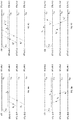
- FIGUREs 4A and 4B depict example procedures in establishing a downstream crosstalk link C 32 in the DSL system.
- FIGUREs 4A and 4B show some high level details of the protocols and procedures that may be used to initiate and provide a better understanding of multilink out-of-band FEXT coupling.
- FTTC cabinet 204 performs precoder training to not only eliminate unwanted crosstalk interference but also to recognize desired traffic on crosstalk link C 32 .
- Precoder 310 in FTTC cabinet 204 performs training for its terminal units XTU-O on its direct links 3-5 as shown in FIGURE 4A and training on terminal unit XTU-R-2 as shown in FIGURE 4B .
- terminal unit XTU-O-3 takes turns training the direct links and the crosstalk link.
- Precoder 310 uses precoding coefficients to modify signals in the lines and transmits the pre-distorted signals downstream from FTTC cabinet 204 to the CPEs 208.
- the introduced pre-distortions in the signals substantially cancel the crosstalk in the signals that are received by the CPEs 208.
- the precoder is trained or initialized using error feedback signals from the CPEs 208, which indicate the crosstalk coupled in the received signals at the CPEs 208.
- terminal unit XTU-O-3 sends a sequence of pilot symbols T 1 downstream to terminal unit XTU-R-3 over direct link C 33 .
- Terminal unit XTU-R-3 receives pilot symbols T 1 and crosstalk symbols X 1 and X 2 from links C 44 and C 55 .
- Terminal unit XTU-R-3 returns corresponding error feedback signals to precoder 310.
- the error feedback signals are then used by precoder 310 to update precoding matrix coefficients and thus adjust the pre-distorted signals until reaching convergence. In this manner, crosstalk symbols X 1 and X 2 are eliminated from the T 1 signal received at the terminal unit XTU-R-3.
- Terminal unit XTU-O-3 sends a sequence of pilot symbols T 1 downstream to terminal unit XTU-R-3 over direct link C 33 .
- Terminal unit XTU-R-2 receives a crosstalk signal T 1 ' of pilot symbols T 1 and cross talk signals X 3 ' and X 4 ' from links C 44 and C 55 .
- Terminal unit XTU-R-2 returns corresponding error feedback signals to precoder 310 through central office 202. The error feedback signals are then used by precoder 310 to update precoding matrix coefficients and thus adjust the pre-distorted signals accordingly.
- precoder 310 maintains an additional set of precoder coefficients for the downstream crosstalk link to terminal unit XTU-R-2 and uses these coefficients when the downstream crosstalk link is activated for data transmission. In this manner, crosstalk symbols X 3 ' and X 4 ' are eliminated from the T 1 ' signal received at the terminal unit XTU-R-2.
- FIGUREs 5A and 5B depict example procedures in establishing an upstream crosstalk link C 32 in the DSL system.
- Canceller 312 in FTTC cabinet 204 is used for uplink crosstalk cancellation.
- FTTC cabinet 204 performs canceller training to not only eliminate unwanted crosstalk interference but also to recognize desired traffic on crosstalk link C 32 .
- Canceller 312 in FTTC cabinet 204 performs training for its terminal units XTU-O on its direct links 3-5 as shown in FIGURE 5A and training on terminal unit XTU-R-2 as shown in FIGURE 5B .
- Uplink crosstalk canceller training is similar to precoder training.
- Terminal Unit XTU-O-3 performs separate canceller training for both terminal units XTU-R-2 and XTU-R-3 sharing the crosstalk link. For the example shown, terminal unit XTU-O-3 takes turns training the direct links and the crosstalk link.
- terminal unit XTU-R-3 sends a sequence of pilot symbols T 2 downstream to terminal unit XTU-O-3 over direct link C 33 .
- Terminal unit XTU-O-3 receives pilot symbols T 2 and crosstalk symbols X 5 and X 6 from links C 44 and C 55 and returns corresponding error feedback signals to canceller 312.
- the error feedback signals are then used by canceller 312 to update canceller matrix coefficients and thus adjust the received signals until reaching convergence. In this manner, crosstalk symbols X 5 and X 6 are eliminated from the T 2 signal received at the terminal unit XTU-O-3.
- terminal unit XTU-R-2 sends a sequence of pilot symbols T 3 upstream to central office 202 over direct link C 22 .
- Terminal unit XTU-O-3 receives on link C 33 a crosstalk signal T 3 ' of pilot symbols T 3 and crosstalk signals X 7 ' and X 8 ' from links C 44 and C 55 and returns corresponding error feedback signals to canceller 312.
- the error feedback signals are then used by canceller 312 to update canceller matrix coefficients and thus adjust the received signals accordingly.
- canceller 312 maintains an additional set of canceller coefficients for the upstream crosstalk link from terminal unit XTU-R-2 and uses these coefficients when the upstream crosstalk link is activated for data transmission. In this manner, crosstalk symbols X 7 ' and X 8 ' are eliminated from the T 3 ' signal received at the terminal unit XTU-O-3.
- crosstalk link C 62 from FTTD cabinet 206 to terminal unit XTU-R-2.
- FIGURE 6 is a flowchart of a method for providing a DSL.
- the steps discussed below refer to a communication device performing the steps. It should be understood that the method can be performed by a communication device comprising a fiber cabinet (such as a FTTC or a FTTD) or by a communication device comprising a CO.
- the communication device receives first link communication parameters of a first communication link.
- the communication device can receive the first link communication parameters via the CO, for example, if the communication device comprises a fiber cabinet.
- the communication device In step 602, the communication device generates a crosstalk establishment signal based on the first link communication parameters.
- the crosstalk establishment signal comprises a signal designed for establishing a crosstalk link to the first communication link.
- the crosstalk establishment signal can be constructed to generate crosstalk of a desired signal strength, signal quality, or according to other crosstalk characteristics.
- the communication device transmits the crosstalk establishment signal over a second communication link.
- the second communication link is located in a common binder with the first communication link for at least a portion of a length of the second communication link.
- the communication device receives crosstalk communication parameters of the first communication link.
- the received crosstalk communication parameters comprise communication parameters of the first communication link.
- the crosstalk communication parameters are received in response to the communication device transmitting the crosstalk establishment signal over the second communication link.
- the received crosstalk communication parameters are related to crosstalk signals generated in the first communication link as a result of transmitting the crosstalk establishment signal over the second communication link.
- the communication device receives the crosstalk communication parameters from the CO, for example, if the communication device comprises a fiber cabinet.
- the communication device generates crosstalk generation parameters based on the received crosstalk communication parameters of the first communication link.
- the crosstalk generation parameters include precoder coefficients and/or digital filter coefficients.
- the crosstalk generation parameters are selected to provide crosstalk between communication links.
- the crosstalk generation parameters can enhance the signal strength and/or signal quality of crosstalk.
- the crosstalk generation parameters can be generated to be used for any communication link in a common binder, or can be generated to be used by a specific communication link or pair of communication links.
- the crosstalk generation parameters are generated for use with crosstalk-intended communications that are exchanged over the second communication link.
- the crosstalk generation parameters can be used in future exchanges of communications over the second communication link wherein crosstalk to the first communication link is intended to be generated.
- the crosstalk generation parameters can be used to ensure crosstalk is generated from the second communication link to the first communication link.
- the crosstalk generation parameters can be used to increase the signal magnitude and/or signal quality of crosstalk generated from the second communication link to the first communication link.
- FIGURE 7 shows a communication device 700.
- the communication device 700 comprises a CO in some examples. In other examples, the communication device 700 comprises a fiber cabinet.
- the communication device 700 in the example shown includes one or more communication ports 701, a processing system 704 coupled to the one or more communication ports 701, and a memory 710 coupled to the processing system 704.
- the memory 710 stores a communication routine 716, among other things.
- the processing system 704 retrieves and executes the communication routine 716.
- the communication device 700 in one example comprises a CO or a fiber cabinet.
- the processing system 704 in one example is configured to exchange first communications over a first communication port 701, with the first communication port 701 adapted to be coupled to a first communication link and a customer premises equipment (CPE), and exchange second communications over a second communication port 701, with the second communication port 701 adapted to be coupled to a second communication link.
- the CO or fiber cabinet exchanges the second communications over the second communication port 701 in order to exchange the second communications with the CPE via crosstalk from the second communication link to the first communication link.
- a total communications rate for the CPE comprises a first communications rate of the first communications exchanged with the CPE combined with a second communications rate of the second communications exchanged with the CPE via crosstalk induced in the first communication link.
- a fiber cabinet (such as a FTTC or FTTD) may be interposed between the CO and the second communication link.
- the CO in this example exchanges communications with the second communication link through the interposed fiber cabinet.
- the communication device 700 in another example comprises a CPE.
- the processing system 704 is configured to exchange first communications over a first communication port 701 adapted to be coupled to a first communication link coupled to a CO, and exchange second communications over a second communication port 701 adapted to be coupled to a second communication link.
- the CPE 20 exchanges the second communications over the second communication port 701 in order to exchange the second communications with the CO via crosstalk from the second communication link to the first communication link.
- a total communications rate for the CPE comprises a first communications rate of the first communications exchanged with the CO combined with a second communications rate of the second communications exchanged with the CO via crosstalk induced in the first communication link.
- this disclosure describes a system and method that uses the FEXT signals from copper twisted pairs connected to proximal cabinets, to improve the rates of customers connected on copper twisted pairs in the same bundle.
- the disclosure enhances the rates by using the additional useable spectrum that is available on a crosstalk link or links.
- the techniques described in this disclosure may be leveraged by a network operator to provide higher rate service to more customers and thus better justify the large capital cost of new cabinet installations.
- some or all of the functions or processes of the one or more of the devices and other hardware devices discussed above are implemented or supported by a computer program that is formed from computer readable program code and that is embodied in a computer readable medium and executed by a processor.
- code includes any type of computer code, including source code, object code, and executable code.
- computer readable medium includes any type of medium capable of being accessed by a computer, such as read only memory (ROM), random access memory (RAM), a hard disk drive, a compact disc (CD), a digital video disc (DVD), or any other type of memory.
Landscapes
- Engineering & Computer Science (AREA)
- Computer Networks & Wireless Communication (AREA)
- Signal Processing (AREA)
- Physics & Mathematics (AREA)
- Electromagnetism (AREA)
- Computing Systems (AREA)
- Cable Transmission Systems, Equalization Of Radio And Reduction Of Echo (AREA)
- Telephonic Communication Services (AREA)
Claims (14)
Austauschen von dritten Übermittlungen mit dem zweiten CPE zur Übertragung mindestens eines Teils der Verkehrsdaten des zweiten CPE über eine dritte Kommunikationsverbindung, die eine Übersprechverbindung ist, die durch die erste verdrillte Doppelleitung in der zweiten verdrillten Doppelleitung induziert wird.
wobei eine Gesamtkommunikationsrate für das CPE eine erste Kommunikationsrate der ersten Übermittlungen, die mit dem CPE ausgetauscht werden, kombiniert mit einer zweiten Kommunikationsrate der zweiten Übermittlungen, die mit dem CPE über in der ersten Kommunikationsverbindung induziertes Übersprechen ausgetauscht werden, umfasst.
Senden eines Übersprech-Herstellungssignals über eine zweite Kommunikationsverbindung;
Empfangen von Übersprech-Kommunikationsparametern einer ersten Kommunikationsverbindung als Reaktion auf Senden des Übersprech-Herstellungssignals über die zweite Kommunikationsverbindung, wobei die Übersprech-Kommunikationsparameter Übersprechsignale betreffen, die in der ersten Kommunikationsverbindung als Ergebnis des Sendens des Übersprech-Herstellungssignals über die zweite Kommunikationsverbindung erzeugt werden; und
Erzeugen von Übersprech-Übertragungsparametern auf der Basis der Übersprech-Kommunikationsparameter der ersten Kommunikationsverbindung, wobei die Übersprech-Übertragungsparameter zur Verwendung mit Übersprech-beabsichtigten Übertragungen über die zweite Kommunikationsverbindung erzeugt werden.
Empfangen von ersten Verbindungskommunikationsparametern der ersten Kommunikationsverbindung; und
Erzeugen des Übersprech-Herstellungssignals auf der Basis der ersten Verbindungskommunikationsparameter.
Applications Claiming Priority (3)
| Application Number | Priority Date | Filing Date | Title |
|---|---|---|---|
| US201461953472P | 2014-03-14 | 2014-03-14 | |
| US201461971888P | 2014-03-28 | 2014-03-28 | |
| PCT/CN2015/074204 WO2015135500A1 (en) | 2014-03-14 | 2015-03-13 | Method and apparatus for providing twisted pair multilink communications |
Publications (3)
| Publication Number | Publication Date |
|---|---|
| EP3103207A1 EP3103207A1 (de) | 2016-12-14 |
| EP3103207A4 EP3103207A4 (de) | 2017-01-04 |
| EP3103207B1 true EP3103207B1 (de) | 2018-09-26 |
Family
ID=54070161
Family Applications (1)
| Application Number | Title | Priority Date | Filing Date |
|---|---|---|---|
| EP15761490.0A Active EP3103207B1 (de) | 2014-03-14 | 2015-03-13 | Verfahren und vorrichtung zur bereitstellung von mehrfachverbindungskommunikation mit verdrillten doppelleitungen |
Country Status (3)
| Country | Link |
|---|---|
| US (1) | US9473240B2 (de) |
| EP (1) | EP3103207B1 (de) |
| WO (1) | WO2015135500A1 (de) |
Families Citing this family (6)
| Publication number | Priority date | Publication date | Assignee | Title |
|---|---|---|---|---|
| EP2770675B1 (de) * | 2012-08-07 | 2017-03-01 | Huawei Technologies Co., Ltd. | Zugangssystem, kommunikationsverfahren und vorrichtung für ein glasfasernetz |
| CN106605370B (zh) * | 2014-03-25 | 2021-05-11 | 领特贝特林共有限责任两合公司 | 用于抑制干扰的设备和方法 |
| EP3560116B1 (de) * | 2016-12-21 | 2021-12-22 | British Telecommunications Public Limited Company | Netzwerkknoten |
| US11411603B2 (en) * | 2017-09-15 | 2022-08-09 | Intel Corporation | Device for transmitting and receiving on a copper wire installed at a customer premise |
| CN109803327B (zh) * | 2017-11-16 | 2020-11-17 | 华为技术有限公司 | 一种通信方法及设备 |
| WO2022251222A1 (en) * | 2021-05-24 | 2022-12-01 | Marvell Asia Pte Ltd | Network optimization for mitigation of crosstalk between network links |
Family Cites Families (23)
| Publication number | Priority date | Publication date | Assignee | Title |
|---|---|---|---|---|
| US7133441B1 (en) * | 1999-02-23 | 2006-11-07 | Actelis Networks Inc. | High speed access system over copper cable plant |
| US7158563B2 (en) * | 2001-06-01 | 2007-01-02 | The Board Of Trustees Of The Leland Stanford Junior University | Dynamic digital communication system control |
| US6782082B2 (en) * | 2002-02-15 | 2004-08-24 | Broadcom Corporation | Method and system for reducing cross-talk and avoiding bridged taps |
| CN1881912A (zh) * | 2005-06-13 | 2006-12-20 | 华澳通讯(上海)有限公司 | 基于多用户的数字用户线捆绑接入方法 |
| EP1760904B1 (de) * | 2005-08-29 | 2011-10-19 | Alcatel Lucent | Verfahren und Vorrichtung zum Messen des Nebensprechens |
| CN100442724C (zh) * | 2005-09-16 | 2008-12-10 | 华为技术有限公司 | 多用户通讯线路串扰测试方法及设备 |
| DE102006051435B4 (de) * | 2006-10-31 | 2009-07-30 | Nokia Siemens Networks Gmbh & Co.Kg | Verfahren, Anordnung und Einrichtung zur Übertragung von Daten über mehrere Kanäle |
| CN101197797B (zh) * | 2006-12-07 | 2011-12-21 | 华为技术有限公司 | 串扰抵消装置、信号处理系统及串扰抵消方法 |
| EP2034622A1 (de) * | 2007-09-10 | 2009-03-11 | Alcatel Lucent | Vorrichtung und entsprechendes Verfahren zur Messung von Nebensprechen |
| BRPI0823226A2 (pt) * | 2008-11-27 | 2015-07-07 | Ericsson Telefon Ab L M | Metodo e sistema para gerenciar recursos de transmissao em um sistema de comunicacao digital |
| US8204100B2 (en) * | 2009-01-15 | 2012-06-19 | Lantiq Deutschland Gmbh | Methods and apparatuses for data transmission |
| CN101908909B (zh) * | 2009-06-05 | 2013-08-14 | 华为技术有限公司 | 估计远端串扰信道的方法和装置 |
| US8498408B2 (en) * | 2009-06-29 | 2013-07-30 | Alcatel Lucent | Crosstalk estimation and power setting based on interpolation in a multi-channel communication system |
| EP2464026B1 (de) * | 2010-12-10 | 2016-07-06 | Alcatel Lucent | Zeitangleichung von Übersprechungserfassungsphasen zwischen mehreren aufeinander treffenden Leitungen |
| WO2012106865A1 (zh) * | 2011-07-05 | 2012-08-16 | 华为技术有限公司 | 生成扩展信道的方法和装置 |
| CN102326334B (zh) * | 2011-08-10 | 2014-03-05 | 华为技术有限公司 | 用于分析线路的串扰的方法及装置 |
| WO2013026479A1 (en) | 2011-08-24 | 2013-02-28 | Telefonaktiebolaget Lm Ericsson (Publ) | Adjusted transmission in xdsl |
| US9531491B2 (en) * | 2012-02-13 | 2016-12-27 | Lantiq Deutschland Gmbh | Communication method, apparatus and system |
| EP2675099A1 (de) * | 2012-06-11 | 2013-12-18 | Lantiq Deutschland GmbH | Ratenadaptives dynamisches Spektrummanagement |
| US9509484B2 (en) * | 2012-10-25 | 2016-11-29 | Sckipio Technologies S.I Ltd | Scheme system and method for power saving in vectored communications |
| US9531866B2 (en) * | 2012-12-21 | 2016-12-27 | Telefonaktiebolaget Lm Ericsson (Publ) | Mitigation of disconnect events in vectoring based DSL systems |
| EP2989780B1 (de) * | 2013-03-01 | 2020-09-16 | Assia Spe, Llc | Systeme und verfahren zur verwaltung von gemischten einsätzen von vektorisiertem und nichtvektorisiertem vdsl |
| CN105191272B (zh) * | 2013-05-05 | 2018-02-23 | 领特德国公司 | 使用准备加入群组来训练经向量化系统中的多个线路的优化 |
-
2015
- 2015-03-13 US US14/657,796 patent/US9473240B2/en active Active
- 2015-03-13 WO PCT/CN2015/074204 patent/WO2015135500A1/en not_active Ceased
- 2015-03-13 EP EP15761490.0A patent/EP3103207B1/de active Active
Non-Patent Citations (1)
| Title |
|---|
| None * |
Also Published As
| Publication number | Publication date |
|---|---|
| EP3103207A4 (de) | 2017-01-04 |
| US20150263809A1 (en) | 2015-09-17 |
| EP3103207A1 (de) | 2016-12-14 |
| WO2015135500A1 (en) | 2015-09-17 |
| US9473240B2 (en) | 2016-10-18 |
Similar Documents
| Publication | Publication Date | Title |
|---|---|---|
| EP2876817B1 (de) | Verfahren, vorrichtung und system kompatibel mit konventionellem vdsl2-benutzerendgerät | |
| US9473240B2 (en) | Method and apparatus for providing twisted pair multilink communications | |
| EP3154230B1 (de) | Übersprechungsbeurteilungsverfahren, -vorrichtung und -system | |
| US20140029406A1 (en) | Time Division Multiple Access Far End Crosstalk Channel Estimation | |
| US10615845B2 (en) | Line synchronization method in OSD system, system, and vectoring control entity | |
| US20100074312A1 (en) | High speed multiple user multiple loop dsl system | |
| WO2016019378A1 (en) | Method and apparatus for crosstalk management among different vectored groups | |
| CN111108719A (zh) | 用于协调通信系统中的fdx和tdd通信的方法和装置 | |
| KR101403590B1 (ko) | G.hn 기술을 엑세스 네트워크에 적용하기 위한 방법 | |
| CN110100406B (zh) | 用于有线传输介质上的全双工通信的方法和装置 | |
| KR20160130386A (ko) | 멀티-심볼 레이트 벡터링을 수행하기 위한 방법 및 장치 | |
| EP2136476B1 (de) | Verfahren und Vorrichtung zur Datenverarbeitung und Kommunikationssystem mit einer derartigen Vorrichtung | |
| KR101911809B1 (ko) | 벡터화된 시스템 내의 특수 동작 채널 | |
| CN105379134B (zh) | 一种dsl系统中抵消线路串扰的方法、设备和系统 | |
| US8908489B2 (en) | Method and device for data processing and communication system comprising such device | |
| EP3284180A1 (de) | Leitungsgruppierung zur übersprechvermeidung | |
| EP3720166A1 (de) | Verfahren und vorrichtung zur verarbeitung eines initialisierungssignals | |
| WO2015196189A1 (en) | Methods and apparatuses for employing a sub-band approach towards doubling transmission bandwidth for dmt systems |
Legal Events
| Date | Code | Title | Description |
|---|---|---|---|
| PUAI | Public reference made under article 153(3) epc to a published international application that has entered the european phase |
Free format text: ORIGINAL CODE: 0009012 |
|
| STAA | Information on the status of an ep patent application or granted ep patent |
Free format text: STATUS: REQUEST FOR EXAMINATION WAS MADE |
|
| 17P | Request for examination filed |
Effective date: 20160906 |
|
| AK | Designated contracting states |
Kind code of ref document: A1 Designated state(s): AL AT BE BG CH CY CZ DE DK EE ES FI FR GB GR HR HU IE IS IT LI LT LU LV MC MK MT NL NO PL PT RO RS SE SI SK SM TR |
|
| AX | Request for extension of the european patent |
Extension state: BA ME |
|
| A4 | Supplementary search report drawn up and despatched |
Effective date: 20161206 |
|
| RIC1 | Information provided on ipc code assigned before grant |
Ipc: H04J 99/00 20090101AFI20161130BHEP |
|
| STAA | Information on the status of an ep patent application or granted ep patent |
Free format text: STATUS: EXAMINATION IS IN PROGRESS |
|
| DAV | Request for validation of the european patent (deleted) | ||
| DAX | Request for extension of the european patent (deleted) | ||
| 17Q | First examination report despatched |
Effective date: 20170530 |
|
| GRAP | Despatch of communication of intention to grant a patent |
Free format text: ORIGINAL CODE: EPIDOSNIGR1 |
|
| STAA | Information on the status of an ep patent application or granted ep patent |
Free format text: STATUS: GRANT OF PATENT IS INTENDED |
|
| INTG | Intention to grant announced |
Effective date: 20180315 |
|
| GRAS | Grant fee paid |
Free format text: ORIGINAL CODE: EPIDOSNIGR3 |
|
| GRAJ | Information related to disapproval of communication of intention to grant by the applicant or resumption of examination proceedings by the epo deleted |
Free format text: ORIGINAL CODE: EPIDOSDIGR1 |
|
| GRAL | Information related to payment of fee for publishing/printing deleted |
Free format text: ORIGINAL CODE: EPIDOSDIGR3 |
|
| STAA | Information on the status of an ep patent application or granted ep patent |
Free format text: STATUS: EXAMINATION IS IN PROGRESS |
|
| GRAR | Information related to intention to grant a patent recorded |
Free format text: ORIGINAL CODE: EPIDOSNIGR71 |
|
| STAA | Information on the status of an ep patent application or granted ep patent |
Free format text: STATUS: GRANT OF PATENT IS INTENDED |
|
| GRAA | (expected) grant |
Free format text: ORIGINAL CODE: 0009210 |
|
| STAA | Information on the status of an ep patent application or granted ep patent |
Free format text: STATUS: THE PATENT HAS BEEN GRANTED |
|
| INTC | Intention to grant announced (deleted) | ||
| RIC1 | Information provided on ipc code assigned before grant |
Ipc: H04B 3/32 20060101ALI20180806BHEP Ipc: H04B 10/27 20130101ALI20180806BHEP Ipc: H04J 99/00 20090101AFI20180806BHEP |
|
| INTG | Intention to grant announced |
Effective date: 20180810 |
|
| AK | Designated contracting states |
Kind code of ref document: B1 Designated state(s): AL AT BE BG CH CY CZ DE DK EE ES FI FR GB GR HR HU IE IS IT LI LT LU LV MC MK MT NL NO PL PT RO RS SE SI SK SM TR |
|
| REG | Reference to a national code |
Ref country code: GB Ref legal event code: FG4D |
|
| REG | Reference to a national code |
Ref country code: CH Ref legal event code: EP |
|
| REG | Reference to a national code |
Ref country code: AT Ref legal event code: REF Ref document number: 1047279 Country of ref document: AT Kind code of ref document: T Effective date: 20181015 |
|
| REG | Reference to a national code |
Ref country code: IE Ref legal event code: FG4D |
|
| REG | Reference to a national code |
Ref country code: DE Ref legal event code: R096 Ref document number: 602015017129 Country of ref document: DE |
|
| REG | Reference to a national code |
Ref country code: NL Ref legal event code: MP Effective date: 20180926 |
|
| PG25 | Lapsed in a contracting state [announced via postgrant information from national office to epo] |
Ref country code: RS Free format text: LAPSE BECAUSE OF FAILURE TO SUBMIT A TRANSLATION OF THE DESCRIPTION OR TO PAY THE FEE WITHIN THE PRESCRIBED TIME-LIMIT Effective date: 20180926 Ref country code: LT Free format text: LAPSE BECAUSE OF FAILURE TO SUBMIT A TRANSLATION OF THE DESCRIPTION OR TO PAY THE FEE WITHIN THE PRESCRIBED TIME-LIMIT Effective date: 20180926 Ref country code: GR Free format text: LAPSE BECAUSE OF FAILURE TO SUBMIT A TRANSLATION OF THE DESCRIPTION OR TO PAY THE FEE WITHIN THE PRESCRIBED TIME-LIMIT Effective date: 20181227 Ref country code: NO Free format text: LAPSE BECAUSE OF FAILURE TO SUBMIT A TRANSLATION OF THE DESCRIPTION OR TO PAY THE FEE WITHIN THE PRESCRIBED TIME-LIMIT Effective date: 20181226 Ref country code: FI Free format text: LAPSE BECAUSE OF FAILURE TO SUBMIT A TRANSLATION OF THE DESCRIPTION OR TO PAY THE FEE WITHIN THE PRESCRIBED TIME-LIMIT Effective date: 20180926 Ref country code: SE Free format text: LAPSE BECAUSE OF FAILURE TO SUBMIT A TRANSLATION OF THE DESCRIPTION OR TO PAY THE FEE WITHIN THE PRESCRIBED TIME-LIMIT Effective date: 20180926 Ref country code: BG Free format text: LAPSE BECAUSE OF FAILURE TO SUBMIT A TRANSLATION OF THE DESCRIPTION OR TO PAY THE FEE WITHIN THE PRESCRIBED TIME-LIMIT Effective date: 20181226 |
|
| REG | Reference to a national code |
Ref country code: LT Ref legal event code: MG4D |
|
| PG25 | Lapsed in a contracting state [announced via postgrant information from national office to epo] |
Ref country code: LV Free format text: LAPSE BECAUSE OF FAILURE TO SUBMIT A TRANSLATION OF THE DESCRIPTION OR TO PAY THE FEE WITHIN THE PRESCRIBED TIME-LIMIT Effective date: 20180926 Ref country code: AL Free format text: LAPSE BECAUSE OF FAILURE TO SUBMIT A TRANSLATION OF THE DESCRIPTION OR TO PAY THE FEE WITHIN THE PRESCRIBED TIME-LIMIT Effective date: 20180926 Ref country code: HR Free format text: LAPSE BECAUSE OF FAILURE TO SUBMIT A TRANSLATION OF THE DESCRIPTION OR TO PAY THE FEE WITHIN THE PRESCRIBED TIME-LIMIT Effective date: 20180926 |
|
| REG | Reference to a national code |
Ref country code: AT Ref legal event code: MK05 Ref document number: 1047279 Country of ref document: AT Kind code of ref document: T Effective date: 20180926 |
|
| PG25 | Lapsed in a contracting state [announced via postgrant information from national office to epo] |
Ref country code: RO Free format text: LAPSE BECAUSE OF FAILURE TO SUBMIT A TRANSLATION OF THE DESCRIPTION OR TO PAY THE FEE WITHIN THE PRESCRIBED TIME-LIMIT Effective date: 20180926 Ref country code: IT Free format text: LAPSE BECAUSE OF FAILURE TO SUBMIT A TRANSLATION OF THE DESCRIPTION OR TO PAY THE FEE WITHIN THE PRESCRIBED TIME-LIMIT Effective date: 20180926 Ref country code: EE Free format text: LAPSE BECAUSE OF FAILURE TO SUBMIT A TRANSLATION OF THE DESCRIPTION OR TO PAY THE FEE WITHIN THE PRESCRIBED TIME-LIMIT Effective date: 20180926 Ref country code: CZ Free format text: LAPSE BECAUSE OF FAILURE TO SUBMIT A TRANSLATION OF THE DESCRIPTION OR TO PAY THE FEE WITHIN THE PRESCRIBED TIME-LIMIT Effective date: 20180926 Ref country code: ES Free format text: LAPSE BECAUSE OF FAILURE TO SUBMIT A TRANSLATION OF THE DESCRIPTION OR TO PAY THE FEE WITHIN THE PRESCRIBED TIME-LIMIT Effective date: 20180926 Ref country code: NL Free format text: LAPSE BECAUSE OF FAILURE TO SUBMIT A TRANSLATION OF THE DESCRIPTION OR TO PAY THE FEE WITHIN THE PRESCRIBED TIME-LIMIT Effective date: 20180926 Ref country code: IS Free format text: LAPSE BECAUSE OF FAILURE TO SUBMIT A TRANSLATION OF THE DESCRIPTION OR TO PAY THE FEE WITHIN THE PRESCRIBED TIME-LIMIT Effective date: 20190126 Ref country code: PL Free format text: LAPSE BECAUSE OF FAILURE TO SUBMIT A TRANSLATION OF THE DESCRIPTION OR TO PAY THE FEE WITHIN THE PRESCRIBED TIME-LIMIT Effective date: 20180926 Ref country code: AT Free format text: LAPSE BECAUSE OF FAILURE TO SUBMIT A TRANSLATION OF THE DESCRIPTION OR TO PAY THE FEE WITHIN THE PRESCRIBED TIME-LIMIT Effective date: 20180926 |
|
| PG25 | Lapsed in a contracting state [announced via postgrant information from national office to epo] |
Ref country code: SK Free format text: LAPSE BECAUSE OF FAILURE TO SUBMIT A TRANSLATION OF THE DESCRIPTION OR TO PAY THE FEE WITHIN THE PRESCRIBED TIME-LIMIT Effective date: 20180926 Ref country code: SM Free format text: LAPSE BECAUSE OF FAILURE TO SUBMIT A TRANSLATION OF THE DESCRIPTION OR TO PAY THE FEE WITHIN THE PRESCRIBED TIME-LIMIT Effective date: 20180926 Ref country code: PT Free format text: LAPSE BECAUSE OF FAILURE TO SUBMIT A TRANSLATION OF THE DESCRIPTION OR TO PAY THE FEE WITHIN THE PRESCRIBED TIME-LIMIT Effective date: 20190126 |
|
| REG | Reference to a national code |
Ref country code: DE Ref legal event code: R097 Ref document number: 602015017129 Country of ref document: DE |
|
| PG25 | Lapsed in a contracting state [announced via postgrant information from national office to epo] |
Ref country code: DK Free format text: LAPSE BECAUSE OF FAILURE TO SUBMIT A TRANSLATION OF THE DESCRIPTION OR TO PAY THE FEE WITHIN THE PRESCRIBED TIME-LIMIT Effective date: 20180926 |
|
| PLBE | No opposition filed within time limit |
Free format text: ORIGINAL CODE: 0009261 |
|
| STAA | Information on the status of an ep patent application or granted ep patent |
Free format text: STATUS: NO OPPOSITION FILED WITHIN TIME LIMIT |
|
| 26N | No opposition filed |
Effective date: 20190627 |
|
| REG | Reference to a national code |
Ref country code: DE Ref legal event code: R119 Ref document number: 602015017129 Country of ref document: DE |
|
| PG25 | Lapsed in a contracting state [announced via postgrant information from national office to epo] |
Ref country code: SI Free format text: LAPSE BECAUSE OF FAILURE TO SUBMIT A TRANSLATION OF THE DESCRIPTION OR TO PAY THE FEE WITHIN THE PRESCRIBED TIME-LIMIT Effective date: 20180926 Ref country code: MC Free format text: LAPSE BECAUSE OF FAILURE TO SUBMIT A TRANSLATION OF THE DESCRIPTION OR TO PAY THE FEE WITHIN THE PRESCRIBED TIME-LIMIT Effective date: 20180926 |
|
| PG25 | Lapsed in a contracting state [announced via postgrant information from national office to epo] |
Ref country code: LU Free format text: LAPSE BECAUSE OF NON-PAYMENT OF DUE FEES Effective date: 20190313 |
|
| REG | Reference to a national code |
Ref country code: BE Ref legal event code: MM Effective date: 20190331 |
|
| PG25 | Lapsed in a contracting state [announced via postgrant information from national office to epo] |
Ref country code: IE Free format text: LAPSE BECAUSE OF NON-PAYMENT OF DUE FEES Effective date: 20190313 Ref country code: DE Free format text: LAPSE BECAUSE OF NON-PAYMENT OF DUE FEES Effective date: 20191001 |
|
| PG25 | Lapsed in a contracting state [announced via postgrant information from national office to epo] |
Ref country code: FR Free format text: LAPSE BECAUSE OF NON-PAYMENT OF DUE FEES Effective date: 20190331 Ref country code: BE Free format text: LAPSE BECAUSE OF NON-PAYMENT OF DUE FEES Effective date: 20190331 |
|
| PG25 | Lapsed in a contracting state [announced via postgrant information from national office to epo] |
Ref country code: TR Free format text: LAPSE BECAUSE OF FAILURE TO SUBMIT A TRANSLATION OF THE DESCRIPTION OR TO PAY THE FEE WITHIN THE PRESCRIBED TIME-LIMIT Effective date: 20180926 |
|
| PG25 | Lapsed in a contracting state [announced via postgrant information from national office to epo] |
Ref country code: MT Free format text: LAPSE BECAUSE OF NON-PAYMENT OF DUE FEES Effective date: 20190313 |
|
| PG25 | Lapsed in a contracting state [announced via postgrant information from national office to epo] |
Ref country code: CY Free format text: LAPSE BECAUSE OF FAILURE TO SUBMIT A TRANSLATION OF THE DESCRIPTION OR TO PAY THE FEE WITHIN THE PRESCRIBED TIME-LIMIT Effective date: 20180926 |
|
| PG25 | Lapsed in a contracting state [announced via postgrant information from national office to epo] |
Ref country code: HU Free format text: LAPSE BECAUSE OF FAILURE TO SUBMIT A TRANSLATION OF THE DESCRIPTION OR TO PAY THE FEE WITHIN THE PRESCRIBED TIME-LIMIT; INVALID AB INITIO Effective date: 20150313 |
|
| PG25 | Lapsed in a contracting state [announced via postgrant information from national office to epo] |
Ref country code: MK Free format text: LAPSE BECAUSE OF FAILURE TO SUBMIT A TRANSLATION OF THE DESCRIPTION OR TO PAY THE FEE WITHIN THE PRESCRIBED TIME-LIMIT Effective date: 20180926 |
|
| PGFP | Annual fee paid to national office [announced via postgrant information from national office to epo] |
Ref country code: GB Payment date: 20250130 Year of fee payment: 11 |
|
| PGFP | Annual fee paid to national office [announced via postgrant information from national office to epo] |
Ref country code: CH Payment date: 20250401 Year of fee payment: 11 |