EP3103306B1 - Verfahren, drahtlose vorrichtung, basisstation und kandidatenrelaisstation zur unterstützung von d2d-kommunikation über ein relais - Google Patents
Verfahren, drahtlose vorrichtung, basisstation und kandidatenrelaisstation zur unterstützung von d2d-kommunikation über ein relais Download PDFInfo
- Publication number
- EP3103306B1 EP3103306B1 EP14706973.6A EP14706973A EP3103306B1 EP 3103306 B1 EP3103306 B1 EP 3103306B1 EP 14706973 A EP14706973 A EP 14706973A EP 3103306 B1 EP3103306 B1 EP 3103306B1
- Authority
- EP
- European Patent Office
- Prior art keywords
- wireless device
- relay
- base station
- candidate relay
- candidate
- Prior art date
- Legal status (The legal status is an assumption and is not a legal conclusion. Google has not performed a legal analysis and makes no representation as to the accuracy of the status listed.)
- Active
Links
Images



Classifications
-
- H—ELECTRICITY
- H04—ELECTRIC COMMUNICATION TECHNIQUE
- H04W—WIRELESS COMMUNICATION NETWORKS
- H04W76/00—Connection management
- H04W76/10—Connection setup
- H04W76/14—Direct-mode setup
-
- H—ELECTRICITY
- H04—ELECTRIC COMMUNICATION TECHNIQUE
- H04W—WIRELESS COMMUNICATION NETWORKS
- H04W24/00—Supervisory, monitoring or testing arrangements
- H04W24/10—Scheduling measurement reports ; Arrangements for measurement reports
-
- H—ELECTRICITY
- H04—ELECTRIC COMMUNICATION TECHNIQUE
- H04W—WIRELESS COMMUNICATION NETWORKS
- H04W40/00—Communication routing or communication path finding
- H04W40/02—Communication route or path selection, e.g. power-based or shortest path routing
- H04W40/22—Communication route or path selection, e.g. power-based or shortest path routing using selective relaying for reaching a BTS [Base Transceiver Station] or an access point
-
- H—ELECTRICITY
- H04—ELECTRIC COMMUNICATION TECHNIQUE
- H04W—WIRELESS COMMUNICATION NETWORKS
- H04W40/00—Communication routing or communication path finding
- H04W40/02—Communication route or path selection, e.g. power-based or shortest path routing
-
- H—ELECTRICITY
- H04—ELECTRIC COMMUNICATION TECHNIQUE
- H04W—WIRELESS COMMUNICATION NETWORKS
- H04W88/00—Devices specially adapted for wireless communication networks, e.g. terminals, base stations or access point devices
- H04W88/02—Terminal devices
- H04W88/04—Terminal devices adapted for relaying to or from another terminal or user
Definitions
- the present disclosure relates generally to methods, wireless devices and a base station of a radio network, for supporting D2D communication between a first wireless device and a second wireless device over a relay wireless device.
- each wireless device communicates radio signals with a serving base station of the radio network by sending uplink radio signals to the base station as well as receiving downlink radio signals from the base station.
- This is the traditional way of communication in a radio network also when the two wireless devices are located somewhat close to one another and being served by the same base station.
- This transmission mode will be referred to as a cellular mode of communication.
- Recently, techniques have been developed to enable such wireless devices in a radio network to communicate radio signals with each other directly, as controlled by the radio network and using frequency spectrum licensed to the network, such that each wireless device receives and decodes the actual radio signals that are transmitted from the opposite, or "peer", wireless device.
- Bluetooth is another example of direct communication between wireless devices, although without control or involvement by any network and using unlicensed frequency spectrum..
- Communication of radio signals may thus take place directly between the two wireless devices without the radio signals being communicated over the radio network via one or more base stations, which is a transmission mode that will be referred to as a direct mode of communication.
- the serving base station allocates radio resources, e.g. defined by time and/or frequency, which the wireless devices are allowed to use in the direct communication.
- Such direct radio communication between two wireless devices is commonly referred to as "Device-to-Device, D2D, communication" or terminal-to- terminal communication.
- wireless device In the field of cellular radio technology, the term “wireless device” is usually used and will be used in this disclosure to represent any wireless communication entity capable of radio communication with a cellular radio network including receiving and sending radio signals.
- UE User Equipment
- Another common term in this field is "User Equipment, UE” which is often used for various wireless devices such as e.g. mobile telephones, tablets and laptop computers.
- UE User Equipment
- a wireless device in this context is not necessarily operated by a human user. It could also be a machine-to-machine type of device operating automatically such as a sensor, counter or measuring entity.
- base station sometimes also referred to as a network node, radio node, e-NodeB, eNB, NB, base transceiver station, access point, etc.
- the base station described here may, without limitation, be a so-called macro base station or a low power base station such as a micro, pico, femto, Wifi or relay node, to mention some customary examples.
- the terms "network node” and "User Equipment, UE” can further be used instead of base station and wireless device, respectively.
- the above D2D communication may thus be employed whenever the two wireless devices, also referred to as “peer devices” or just “peers”, are close enough to one another to be able to receive and decode direct radio signals from the opposite peer. Thereby, it may be possible to reduce transmit power in the area and also to reduce interference, as compared to what is required to enable a serving base station to communicate radio signals with the wireless devices in the traditional manner.
- a radio signal transmitted by the wireless device may be successfully received and decoded by the base station provided that the current radio conditions allow for sufficient quality of the received signals.
- the received signal should not be too weak and/or interfered too much by other radio transmissions in the neighborhood for satisfactory reception and decoding.
- the wireless device may be situated close to the cell edge and relatively far from the base station, or in a spot with bad radio coverage, so that the radio signal fades considerably on its way to the base station.
- the wireless device may in that case need to transmit with increased power in order to provide a sufficiently strong signal at the receiving base station, which may cause interference to other nearby communications.
- Another possibility is to add redundant bits which can be used to assist the decoding in the base station's receiver although they occupy precious radio resources such that overall data throughput is reduced.
- a radio signal transmitted by one wireless device may be successfully received and decoded by the other wireless device provided that the current radio conditions allow for sufficient quality of the received signals.
- the requirements for successful reception and decoding are thus similar to the case of cellular mode discussed above.
- a third wireless device as a D2D relay between the two communicating wireless devices where the third wireless device is in a fixed position and utilized as a part of the network infrastructure.
- Patent applications US2012/0250563 A1 , US2012/0287807 A1 and US2010/0157826 A1 disclose such networks.
- a problem with such relays is that deployment is costly and the fixed position of the relay may make it unsuitable for communication, e.g. when one or both of the two communicating wireless is/are positioned too far away from the relay for favorable signal reception.
- a method is performed by a base station of a radio network, for supporting a D2D communication between a first wireless device and a second wireless device over a relay.
- the base station receives from the first wireless device an identity of a candidate relay wireless device and a first quality metric pertaining to a first relay link between the first wireless device and the candidate relay wireless device and to a second relay link between the second wireless device and the candidate relay wireless device.
- the base station further obtains a second quality metric pertaining to a D2D link between the first wireless device and the second wireless device, and obtains also a third quality metric pertaining to a cellular link between the base station and the first wireless device.
- the base station selects a relay mode for the D2D communication with the candidate relay wireless device acting as the relay.
- the base station then instructs the first wireless device, the second wireless device and the candidate relay wireless device to communicate according to the relay mode.
- a base station is operable in a radio network and arranged to support a D2D communication between a first wireless device and a second wireless device over a relay.
- the base station is configured to receive from the first wireless device an identity of a candidate relay wireless device and a first quality metric pertaining to a first relay link between the first wireless device and the candidate relay wireless device and to a second relay link between the second wireless device and the candidate relay wireless device.
- the base station is also configured to obtain a second quality metric pertaining to a D2D link between the first wireless device and the second wireless device, and to obtain a third quality metric pertaining to a cellular link between the base station and the first wireless device.
- the base station is further configured to select a relay mode for the D2D communication with the candidate relay wireless device acting as the relay, and to instruct the first wireless device, the second wireless device and the candidate relay wireless device to communicate according to the relay mode.
- a method is performed by a first wireless device for supporting a D2D communication between the first wireless device and a second wireless device over a relay, the first and second wireless devices being served by a base station of a radio network.
- the first wireless device transmits a beacon which is measurable by a candidate relay wireless device.
- the first wireless device further receives from the candidate relay wireless device an identity of the candidate relay wireless device and a first quality metric pertaining to a first relay link between the first wireless device and the candidate relay wireless device and to a second relay link between the second wireless device and the candidate relay wireless device.
- the first wireless device then sends the identity and the first quality metric of the candidate relay wireless device to the base station, thereby enabling the base station to select a relay mode for the D2D communication with the candidate relay wireless device acting as the relay, based on the first quality metric.
- a first wireless device is arranged to support D2D communication between the first wireless device and a second wireless device over a relay.
- the first wireless device is configured to transmit a beacon which is measurable by a candidate relay wireless device.
- the first wireless device is also configured to receive from the candidate relay wireless device an identity of the candidate relay wireless device and a first quality metric pertaining to a first relay link between the first wireless device and the candidate relay wireless device and to a second relay link between the second wireless device and the candidate relay wireless device.
- the first wireless device is further configured to send the received identity and the first quality metric of the candidate relay wireless device to the base station, thereby enabling the base station to select a relay mode for the D2D communication with the candidate relay wireless device acting as the relay, based on the first quality metric.
- a method is performed by a candidate relay wireless device for supporting a D2D communication between a first wireless device and a second wireless device over a relay, the first and second wireless devices being served by a base station of a radio network.
- the candidate relay wireless device measures beacons transmitted by the first wireless device and by the second wireless device, and detects a possibility to act as said relay between the first and second wireless devices based on the measured beacons.
- the candidate relay wireless device then calculates, based on the measured beacons, a quality metric pertaining to a first relay link between the first wireless device and the candidate relay wireless device and to a second relay link between the second wireless device and the candidate relay wireless device.
- the candidate relay wireless device further transmits an own identity and the calculated quality metric to be received by at least one of the first wireless device and the second wireless device.
- a candidate relay wireless device is arranged to support a D2D communication between a first wireless device and a second wireless device over a relay, the first and second wireless devices being served by the base station of the radio network.
- the candidate relay wireless device is configured to measure beacons transmitted by the first wireless device and by the second wireless device.
- the candidate relay wireless device is also configured to detect a possibility to act as said relay between the first and second wireless devices based on the measured beacons.
- the candidate relay wireless device is further configured to calculate, based on the measured beacons, a quality metric pertaining to a first relay link between the first wireless device and the candidate relay wireless device and to a second relay link between the second wireless device and the candidate relay wireless device.
- the candidate relay wireless device is also configured to transmit an own identity and the calculated quality metric to be received by at least one of the first wireless device and the second wireless device.
- a fitting candidate relay wireless device can be found which in turn enables the base station to effectively compare different available transmission modes and select the relay mode when the relay mode is assessed to provide favourable signal conditions as indicated by the above quality metrics.
- benefits such as improved spectral and energy efficiency, efficient resource utilization, lower transmit power and reduced interference, may be achieved in the radio network.
- wireless devices and base station may be configured and implemented according to different optional embodiments to accomplish further features and benefits, to be described below.
- a favorable communication between two wireless devices may be achieved by employing a D2D communication via an intermediate relay wireless device, which is a transmission mode that will be referred to as a relay mode of communication, when the relay mode is assessed or evaluated to provide better signal quality and/or require less transmission power as compared to the above cellular and direct modes.
- the relay mode is selected when a combination or sum of a first relay link between the first wireless device and the relay wireless device and a second relay link between the second wireless device and the relay wireless device is estimated to provide better signal quality and/or require less transmission power as compared to using a direct link between the first and second wireless devices or using respective cellular links between the base station and the first and second wireless devices.
- This solution is directed to procedures for finding a fitting candidate device to act as relay and for comparing the above-described three transmission modes in order to select the relay mode under certain conditions which will be described below.
- the base station is thus arranged or configured for supporting a D2D communication between a first wireless device and a second wireless device over a relay.
- This procedure thus illustrates how the base station may operate such that the benefits of improved spectral and energy efficiency, efficient resource utilization, lower transmit power and reduced interference may be achieved, among other things.
- a first action 300 illustrates that the base station establishes a connection with the first wireless device and a connection with the second wireless device, which may be done according to regular procedures. These connections are needed to communicate information and messages to and from the respective devices.
- the first wireless device may have issued a request to start a communication session with the second wireless device.
- the base station discovers that it serves both devices, i.e. both devices are located within the coverage area of the base station, the base station is triggered to execute the procedure of evaluating a number of available transmission modes including the above-described cellular, direct and relay modes, and select one of the available transmission modes for the two-way communication as follows.
- the following actions assume that the first wireless device has recognized that the relay mode may be possible to employ for the D2D communication and that there is at least one potential relay candidate wireless device present which is able to communicate radio signals directly with both of the first and second wireless devices. A procedure of how this may be conducted will be described in more detail later below.
- the base station receives from the first wireless device an identity of a candidate relay wireless device and a first quality metric denoted "G eq " which pertains to a first relay link between the first wireless device and the candidate relay wireless device and to a second relay link between the second wireless device and the candidate relay wireless device.
- the first quality metric G eq indicates the quality of the first relay link and the second relay link if they both were to be used in a relay mode for the D2D communication with the candidate relay wireless device acting as the relay.
- quality metric should be generally understood as any parameter that in some way indicates the quality of a radio link.
- quality metric parameters include Signal to Interference and Noise Ratio, SINR, signal strength, Bit Error Rate, BER, path loss, and some fading condition parameter.
- G1R may be the signal strength of signals received over the first relay link and G2R may be the signal strength of signals received over the second relay link.
- the first quality metric G eq is dependent on adequate quality of both relay links such that this parameter will be much reduced if one of G1R and G2R is significantly smaller than the other.
- the base station obtains a second quality metric denoted "G12" which pertains to a D2D link, i.e. direct link, between the first wireless device and the second wireless device.
- the base station also obtains a third quality metric denoted "G1BS" which pertains to a cellular link between the base station and the first wireless device.
- the base station may optionally also obtain a similar quality metric which pertains to a cellular link between the base station and the second wireless device which may be used in the manner described herein.
- Action 206 assumes that at least the third quality metric G1BS of the cellular link to the first wireless device is obtained as an indication of link quality of the cellular mode.
- the second and third quality metrics G12, G1BS may be obtained from measurements made by one or both of the devices and/or by the base station on various signals such as reference signals which are typically transmitted in wireless networks for the purpose of enabling link quality measurements.
- One or both of the two wireless devices may thus perform D2D link measurements on a beacon signal or the like transmitted from the opposite device.
- the base station may obtain the second quality metric G12 based on a D2D radio link quality report received from at least one of the first and second wireless devices.
- the base station may obtain the third quality metric G1BS based on measurements of the cellular radio link between the base station and the first wireless device. The latter measurements of the cellular radio link may be performed by the base station and/or by the first wireless device.
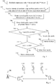
- Another action 308 illustrates that the base station checks whether the first quality metric G eq is greater than both of the second quality metric G12 and the third quality metric G1BS, where the term "max(G12, G1BS)" indicates the greatest value of G12 and G1BS. If so, the base station in this example selects the relay mode in an action 310, for the D2D communication with the candidate relay wireless device acting as the relay. In other words, when the first quality metric G eq indicates a better link quality than both the second quality metric G12 and the third quality metric G1BS, regardless of which type of quality metric parameter is used, the base station selects the relay mode for the D2D communication. The base station then accordingly instructs the first wireless device, the second wireless device and the candidate relay wireless device to communicate according to the relay mode, in an action 312.
- the base station checks whether the second quality metric G12 is greater than the third quality metric G1BS, in another action 314. If so, it can be deduced that the direct mode is more favorable than both the relay mode indicated by G12, and the cellular mode indicated by G1BS. The base station then accordingly selects the direct mode for the D2D communication, in an action 316. If the third quality metric G1BS is found to be greater than the second quality metric G12 in action 314, the base station selects the cellular mode for the D2D communication, in an action 318.
- the base station is able to select the transmission mode that provides the best possible link quality of them all and particularly select the relay mode only when this mode is more favorable than both the cellular and direct modes.
- the base station may accordingly instruct the first and second wireless device, although not shown here.
- the first wireless device has evaluated the available candidate relay wireless devices and selected basically the best one of them to be presented as a "recommended" candidate relay to the base station, which the base station then considers when selecting the transmission mode as in the example of Fig. 3 .
- the first wireless device sends identities and corresponding first quality metrics G eq of the available candidate relay wireless devices to the base station, and in that case it is the base station that evaluates the available candidate relay devices and selects one of them for consideration when selecting the transmission mode.
- the base station may receive from the first wireless device identities of multiple candidate relay wireless devices and their corresponding first quality metrics G eq , and selects one of the candidate relay wireless devices to act as the relay in the D2D communication when the relay mode is selected.
- Fig. 4 illustrates a scenario for supporting a two-way D2D communication between two wireless devices D1, D2 being served by a base station BS.
- both devices D1, D2 transmit measurable beacons.
- a number of candidate relay wireless devices CR1, CR2, CR3... measure the signal strength of the beacons transmitted by the devices D1, D2 and identify themselves as potential candidates for acting as relay in the two-way D2D communication.
- each one of the devices CR1, CR2, CR3... detects a possibility to act as relay, e.g. when the signal strength measured on the beacons from D1 and D2 exceeds some threshold value.
- each candidate relay device CR1, CR2, CR3... determines the above-described "first" quality metric G eq based on the beacons transmitted by devices D1, D2. It has been described above how the first quality metric G eq could be determined from qualities, e.g. received signal strength, of respective relay links between relay and devices D1, D2.
- the candidate relay devices CR1, CR2, CR3... start to transmit their respective beacons, indicated by dashed arrows, which contain their identities as well as their determined first quality metric G eq .
- the beacons transmitted by devices CR1, CR2, CR3... are received by the two wireless devices D1, D2.
- the devices D1, D2 may exchange information extracted from their received beacons and at least one of them, D1 for example, may evaluate the candidate relay devices CR1, CR2, CR3... based on the received first quality metric G eq of each candidate relay.
- each first quality metric G eq reflects the quality of a combination of the respective relay links between the communicating devices D1, D2 and each candidate relay device CR1, CR2, CR3..., i.e. the "end-to-end" link quality between D1 and D2 if the candidate relay device would be used in the "two-hop" relay mode.
- Selection of the best candidate relay wireless device to use may now be conducted in two alternative ways as follows.
- the first device D1 sends identities of the multiple candidate relay wireless devices CR1, CR2, CR3... and their corresponding first quality metrics G eq valid for the respective candidate relays, to the base station BS.
- the base station BS can evaluate the candidate relay device CR1, CR2, CR3... and select the "best" one of them at least based on their first quality metrics G eq .
- the base station may then evaluate different transmission modes and possibly select the relay mode with the selected candidate relay device, if that mode is deemed favorable compared to other available transmission modes such as the above-described cellular and direct modes. This mode selection procedure as such has been described above when discussing actions 308-318.
- At least one of the devices D1, D2 evaluates the candidate relay devices CR1, CR2, CR3... and select the "best" one of them based on their first quality metrics G eq .
- the device D1 and/or D2 may select one of the candidate relay devices further based on measurements on signals transmitted from the candidate relay devices in their respective beacons. If both devices D1, D2 select their own preferred or recommended relay device, this information may be exchanged between the two devices D1, D2 to agree on a common candidate.
- one of the devices, in this case device D1 may be appointed to act as master which decides which candidate relay device to choose and reports it to the base station BS.
- Device D1 then accordingly sends the identity and the first quality metric G eq of the selected one of the candidate relay devices CR1, CR2, CR3..., to the serving base station BS.
- the base station is then able to evaluate different transmission modes based on the reported relay device identity and first quality metric G eq , and possibly select the relay mode in the manner described herein.
- Fig. 5 illustrates an example of a signalling procedure that may be used for supporting a D2D communication in the relay mode.
- the procedure involves a base station 500, two wireless devices 502 and 504 denoted D1 and D2 which correspond to the above first and second wireless devices, respectively, and a candidate relay wireless device 506 called candidate relay "CR" for short.
- a candidate relay wireless device 506 called candidate relay "CR" for short.
- the first device D1 has requested a two-way communication with the second device D2.
- Initial actions 5:1a and 5:1b illustrate that connections are established between the base station 500 and the two devices D1 and D2, at least for signaling over respective cellular links.
- Another action 5:2 illustrates that the devices D1, D2 detect their proximity to one another, e.g. by receiving signals from the opposite device in a conventional peer discovery procedure which is somewhat outside the scope of this solution.
- the base station 500 may configure beacons for the devices D1, D2 to transmit, e.g. instructing them to use certain radio resources in time-frequency and to include certain information in the beacons such as their own identities.
- the devices D1, D2 may be instructed to include both their own identity and the identity of the respective opposite device in their beacons. Thereby, any nearby wireless device receiving the beacons will know that these two devices could potentially be helped by a relay in a D2D communication.
- device D1 and device D2 accordingly transmit their beacons as shown by actions 5:3a and 5:3b, which beacons are received and measured by the candidate relay CR. Since each beacon from devices D1, D2 contains the identities of both D1 and D2, the candidate relay CR is able to deduce that these two devices D1, D2 may be helped by a relay device in a D2D communication in the relay mode.
- Another action 5:4 thus illustrates that the candidate relay CR measures the signal strength of both beacons and thereby detects a possibility to act as relay provided that the beacons can be received and decoded properly, that is when the signal strength is sufficiently high.
- the candidate relay CR also calculates the above-described first quality metric G eq pertaining to the relay links between the candidate relay CR and the first and second devices D1 D2, respectively, based on the measured beacons.
- the candidate relay CR now transmits its own beacon, shown by another action 5:5, containing its own identity and the calculated first quality metric G eq , which is received by both devices D1 and D2 in this example.
- the beacon from the candidate relay CR may further contain identities of the device pair D1, D2 to facilitate recognition of the beacon.
- the devices D1 and D2 may receive a first quality metric G eq from one or more further candidate relays 506, e.g. as described for Fig. 4 above.
- FIG. 5:6a and 5:6b illustrate that devices D1 and D2 may measure the beacon and evaluate the candidate relay CR, as well as any further candidate relays 506 if present, based on the first quality metric G eq , and possibly also based on measurements of the beacon transmitted by the candidate relay CR.
- the devices D1 and D2 may also exchange the results of the evaluation in an optional action 5:7, e.g. as described for Fig. 4 , e.g. to agree on a common recommended candidate relay CR.
- the first wireless device D1 now sends the identity and the first quality metric G eq of the candidate relay CR to the base station 500, in an action 5:8.
- the base station is thereby enabled to select the relay mode for the D2D communication with the candidate relay wireless device CR acting as the relay, based on the first quality metric G eq , which is shown in another action 5:9.
- a further action 5:10 illustrates that the base station 500 basically establishes the D2D two-way communication over the relay by various suitable signaling with the three involved devices 502, 504 and 506.
- a final action 5:11 illustrates that the D2D two-way communication over the relay is executed accordingly, e.g. involving data sent from D1 to D2 over CR, shown as full arrows, and data sent from D2 to D1 over CR, shown as dashed arrows.
- FIG. 6 An example of a procedure with actions, performed by a first wireless device for supporting a D2D communication between the first wireless device and a second wireless device over a relay, will now be described with reference to the flow chart in Fig. 6 .
- the first and second wireless devices are both being served by a base station of a radio network.
- This procedure thus illustrates how the first wireless device may operate in cooperation with the above-described base station such that the benefits of improved spectral and energy efficiency, efficient resource utilization, lower transmit power and reduced interference may be achieved, among other things.
- a first action 600 illustrates that the first wireless device transmits a beacon which is measurable by a candidate relay wireless device, i.e. by one or more candidate relay wireless devices.
- the first wireless device receives from at least one candidate relay wireless device an identity of the candidate relay wireless device and a first quality metric G eq pertaining to a first relay link between the first wireless device and the candidate relay wireless device and to a second relay link between the second wireless device and the candidate relay wireless device.
- Fig. 6 illustrates an option where the first wireless device selects a candidate relay device.
- the first wireless device may receive identities and corresponding first quality metrics G eq from multiple candidate relay wireless devices in action 602.
- the first wireless device may select one of the candidate relay wireless devices, as shown by an optional action 604, to act as the relay wireless device in the D2D communication, based on the respective first quality metrics G eq , as in Alternative 2 above.
- the first wireless device may select one of the candidate relay wireless devices further based on measurements on signals transmitted from the multiple candidate relay wireless devices, which was illustrated by dashed arrows in Fig. 4 and actions 5:5, 5:6a in Fig. 5 .
- the first wireless device sends the identity and the first quality metric G eq of the candidate relay wireless device, e.g. selected in action 604, to the base station.
- the base station is enabled to select a relay mode for the D2D communication with the candidate relay wireless device acting as the relay, based on the first quality metric G eq .
- the first wireless device sends the identity and first quality metric G eq of all candidate relay wireless devices to the base station in action 606.
- FIG. 7 An example of a procedure with actions, performed by a candidate relay wireless device for supporting a D2D communication between a first wireless device and a second wireless device over a relay, will now be described with reference to the flow chart in Fig. 7 .
- the first and second wireless devices are both being served by a base station of a radio network.
- This procedure thus illustrates how the first wireless device may operate in cooperation with the above-described base station such that the benefits of improved spectral and energy efficiency, efficient resource utilization, lower transmit power and reduced interference may be achieved, among other things.
- a first action 700 illustrates that the candidate relay wireless device measures beacons transmitted by the first wireless device and by the second wireless device, e.g. as illustrated by arrows from D1 and D2 in Fig. 4 and actions 5:3a, 5:3b and 5:4 of Fig. 5 .
- the candidate relay wireless device detects a possibility to act as said relay between the first and second wireless devices based on the measured beacons, e.g. if the signal strength of the received beacons exceed some threshold value.
- the candidate relay wireless device calculates, based on the measured beacons, a quality metric G eq pertaining to a first relay link between the first wireless device and the candidate relay wireless device and to a second relay link between the second wireless device and the candidate relay wireless device, as in action 5:4 of Fig. 5 .
- the candidate relay wireless device transmits an own identity and the calculated quality metric G eq to be received by at least one of the first wireless device and the second wireless device, which corresponds to action 5:5 of Fig. 5 .
- An optional action 708 indicates that the candidate relay wireless device may receive an instruction from the base station to act as the relay in the D2D communication, which corresponds to action 5:11 of Fig. 5 .
- the block diagram in Fig. 8 illustrates a detailed but non-limiting example of how a base station 800, a first wireless device 802 and a candidate relay wireless device 804, respectively, may be structured to bring about the above-described solution and embodiments thereof.
- the base station 800, the first wireless device 802 and the candidate relay wireless device 804 may be configured to operate according to any of the examples and embodiments of employing the solution as described above, where appropriate, and as follows.
- Each of the base station 800, first wireless device 802 and candidate relay wireless device 804 is shown to comprise a communication circuit "C" with suitable radio equipment for transmitting and receiving radio signals with information in the manner described herein.
- the base station 800 may be configured or arranged to perform at least the actions 302-312 of the flow chart in Fig. 3 in the manner described above. These actions may be performed by means of different modules in the base station 800 as follows.
- the base station 800 is operable in a radio network and arranged to support a D2D communication between the first wireless device 802 and a second wireless device, not shown, over a relay.
- the base station 800 may comprise a receiving module 800a which is configured to receive from the first wireless device 802 an identity of a candidate relay wireless device, such as device 804 in this example, and a first quality metric, e.g. G eq above, pertaining to a first relay link between the first wireless device 802 and the candidate relay wireless device 804 and to a second relay link between the second wireless device and the candidate relay wireless device 802, e.g. as described above for action 302.
- a receiving module 800a which is configured to receive from the first wireless device 802 an identity of a candidate relay wireless device, such as device 804 in this example, and a first quality metric, e.g. G eq above, pertaining to a first relay link between the first wireless device 802 and the candidate relay wireless device 804 and to a second relay link between the second wireless device and the candidate relay wireless device 802, e.g. as described above for action 302.
- the base station 800 may also comprise an obtaining module 800b which is configured to obtain a second quality metric, e.g. G12 above, pertaining to a D2D link between the first wireless device 802 and the second wireless device, e.g. as described above for action 304.
- the obtaining module 800b is further configured to obtain a third quality metric, e.g. G1BS above, pertaining to a cellular link between the base station 800 and the first wireless device 802, e.g. as described above for action 306.
- the base station 800 may also comprise a selecting module 800c which is configured to, when the first quality metric indicates a better link quality than both the second quality metric and the third quality metric, select a relay mode for the D2D communication with the candidate relay wireless device 804 acting as the relay, e.g. as described above for action 310.
- a selecting module 800c which is configured to, when the first quality metric indicates a better link quality than both the second quality metric and the third quality metric, select a relay mode for the D2D communication with the candidate relay wireless device 804 acting as the relay, e.g. as described above for action 310.
- the base station 800 may also comprise an instructing module 800d which is configured to instruct the first wireless device 802, the second wireless device and the candidate relay wireless device 804 to communicate according to the relay mode, e.g. as described above for action 312.
- the first wireless device 802 may be configured or arranged to perform at least the actions 600, 602 and 606 of the flow chart in Fig. 6 in the manner described above. These actions may be performed by means of different modules in the first wireless device 802 as follows.
- the first wireless device 802 is arranged to support a D2D communication between the first wireless device 802 and a second wireless device over a relay, the first and second wireless devices being served by the base station 800 of the radio network.
- the first wireless device 802 may comprise a transmitting module 802a which is configured to transmit a beacon which is measurable by a candidate relay wireless device such as device 804 in this example, e.g. as described above for action 600.
- the first wireless device 802 may also comprise a receiving module 802b which is configured to receive from the candidate relay wireless device 804 an identity of the candidate relay wireless device and a first quality metric pertaining to a first relay link between the first wireless device 802 and the candidate relay wireless device 804 and to a second relay link between the second wireless device and the candidate relay wireless device 804, e.g. as described above for action 602.
- a receiving module 802b which is configured to receive from the candidate relay wireless device 804 an identity of the candidate relay wireless device and a first quality metric pertaining to a first relay link between the first wireless device 802 and the candidate relay wireless device 804 and to a second relay link between the second wireless device and the candidate relay wireless device 804, e.g. as described above for action 602.
- the transmitting module 802a may be further configured to send the received identity and the first quality metric of the candidate relay wireless device 804 to the base station 800, e.g. as described above for action 606, thereby enabling the base station 800 to select a relay mode for the D2D communication with the candidate relay wireless device 804 acting as the relay, based on the first quality metric.
- the candidate relay wireless device 804 may be configured or arranged to perform at least the actions 700-706 of the flow chart in Fig. 7 in the manner described above. These actions may be performed by means of different modules in the candidate relay wireless device 804 as follows.
- the candidate relay wireless device 804 is arranged to support a D2D communication between the first wireless device 802 and a second wireless device over a relay, the first and second wireless devices being served by the base station 800 of the radio network.
- the candidate relay wireless device 804 may comprise a measuring module 804a which is configured to measure beacons transmitted by the first wireless device 802 and by the second wireless device, e.g. as described above for action 700.
- the candidate relay wireless device 804 may also comprise a detecting module 804b which is configured to detect a possibility to act as said relay between the first and second wireless devices based on the measured beacons, e.g. as described above for action 702.
- the candidate relay wireless device 804 may also comprise a calculating module 804c which is configured to calculate, based on the measured beacons, a quality metric pertaining to a first relay link between the first wireless device 802 and the candidate relay wireless device 804 and to a second relay link between the second wireless device and the candidate relay wireless device 804, e.g. as described above for action 704.
- a calculating module 804c which is configured to calculate, based on the measured beacons, a quality metric pertaining to a first relay link between the first wireless device 802 and the candidate relay wireless device 804 and to a second relay link between the second wireless device and the candidate relay wireless device 804, e.g. as described above for action 704.
- the candidate relay wireless device 804 may also comprise a transmitting module 804d which is configured to transmit an own identity and the calculated quality metric to be received by at least one of the first wireless device 802 and the second wireless device, e.g. as described above for action 706.
- Fig. 8 illustrates some possible functional modules 800a-d, 802a-b, 804a-d in the base station 800, the first wireless device 802 and the candidate relay wireless device 804, respectively, and the skilled person is able to implement these functional modules in practice using suitable software and hardware.
- the solution is generally not limited to the shown structures of the base station 800, the first wireless device 802 and the candidate relay wireless device 804, and the functional modules 800a-d, 802a-b, 804a-d may be configured to operate according to any of the features described in this disclosure, where appropriate.
- the embodiments and features described herein may be implemented in computer programs each comprising computer readable code which, when run on a base station 800, the first wireless device 802 and the candidate relay wireless device 804, respectively, causes them to perform the above actions e.g. as described for Fig. 3 , 6 and 7 , as well as the appropriate functionality described for the base station 800, the first wireless device 802 and the candidate relay wireless device 804 in Fig. 8 .
- the above-described embodiments may be implemented in respective computer program products each comprising a computer readable medium on which the corresponding computer program is stored.
- Each computer program product may be a compact disc or other carrier suitable for holding the computer program.
- the functional modules 800a-d, 802a-b, 804a-d described above for Fig 8 may be implemented in the respective base station 800, first wireless device 802 and candidate relay wireless device 804 by means of program modules of a respective computer program comprising code means which, when run by a processor "P" causes the base station 800, the first wireless device 802 and the candidate relay wireless device 804 to perform the above-described actions and procedures.
- the processor P may comprise a single Central Processing Unit (CPU), or could comprise two or more processing units.
- the processor P may include a general purpose microprocessor, an instruction set processor and/or related chips sets and/or a special purpose microprocessor such as an Application Specific Integrated Circuit (ASIC).
- ASIC Application Specific Integrated Circuit
- the processor P may also comprise a storage for caching purposes.
- Each computer program may be carried by a computer program product in each of the base station 800, the first wireless device 802 and the candidate relay wireless device 804 in the form of a memory "M" having a computer readable medium and being connected to the processor P.
- Each computer program product or memory M thus comprises a computer readable medium on which the computer program is stored.
- the memory M may be a flash memory, a Random-Access Memory (RAM), a Read-Only Memory (ROM) or an Electrically Erasable Programmable ROM (EEPROM), and different program modules could be distributed on different computer program products in the form of memories within the respective base station 800, first wireless device 802 and candidate relay wireless device 804.
- the above-described functionality of the base station may be implemented as a computer program comprising computer readable code which, when run on the base station, causes the base station to perform the method according to any of the above embodiments where appropriate.
- the base station's operation may also be implemented in a computer program product comprising a computer readable medium on which a computer program is stored, wherein the computer program comprises computer readable code which, when run on a base station, causes the base station to perform the method according to any of the above embodiments where appropriate.
- the above-described functionality of the first wireless device may be implemented as a computer program comprising computer readable code which, when run on the first wireless device, causes the first wireless device to perform the method according to any of the above embodiments where appropriate.
- the first wireless device's operation may also be implemented in a computer program product comprising a computer readable medium on which a computer program is stored, wherein the computer program comprises computer readable code which, when run on a first wireless device, causes the first wireless device to perform the method according to any of the above embodiments where appropriate.
- the above-described functionality of the candidate relay wireless device may be implemented as a computer program comprising computer readable code which, when run on the candidate relay wireless device, causes the candidate relay wireless device to perform the method according to any of the above embodiments where appropriate.
- the candidate relay wireless device's operation may also be implemented in a computer program product comprising a computer readable medium on which a computer program is stored, wherein the computer program comprises computer readable code which, when run on a candidate relay wireless device, causes the candidate relay wireless device to perform the method according to any of the above embodiments where appropriate.
Landscapes
- Engineering & Computer Science (AREA)
- Computer Networks & Wireless Communication (AREA)
- Signal Processing (AREA)
- Mobile Radio Communication Systems (AREA)
Claims (15)
- Verfahren, das von einer Basisstation (BS) eines Funknetzes durchgeführt wird, um eine D2D-Kommunikation zwischen einer ersten drahtlosen Vorrichtung (D1) und einer zweiten drahtlosen Vorrichtung (D2) über ein Relais zu unterstützen, wobei das Verfahren umfasst:- Empfangen (302) von der ersten drahtlosen Vorrichtung (D1) einer Identität einer drahtlosen Kandidatenrelaisvorrichtung (CR) und einer ersten Qualitätsmetrik (Geq), die sich auf eine erste Relaisverbindung zwischen der ersten drahtlosen Vorrichtung (D1) und der drahtlosen Kandidatenrelaisvorrichtung (CR) und auf eine zweite Relaisverbindung zwischen der zweiten drahtlosen Vorrichtung (D2) und der drahtlosen Kandidatenrelaisvorrichtung (CR) bezieht,- Erhalten (304) einer zweiten Qualitätsmetrik (G12), die sich auf eine D2D-Verbindung zwischen der ersten drahtlosen Vorrichtung (D1) und der zweiten drahtlosen Vorrichtung (D2) bezieht,- Erhalten (306) einer dritten Qualitätsmetrik (G1BS), die sich auf eine zellulare Verbindung zwischen der Basisstation (BS) und der ersten drahtlosen Vorrichtung (D1) bezieht,- wenn die erste Qualitätsmetrik (Geq) eine bessere Verbindungsqualität angibt als sowohl die zweite Qualitätsmetrik (G12) als auch die dritte Qualitätsmetrik (G1BS), Auswählen (310) eines Relaismodus für die D2D-Kommunikation mit der als Relais fungierenden drahtlosen Kandidatenrelaisvorrichtung (CR) und- Anweisen (312) der ersten drahtlosen Vorrichtung (D1), der zweiten drahtlosen Vorrichtung (D2) und der drahtlosen Kandidatenrelaisvorrichtung (CR), gemäß dem Relaismodus zu kommunizieren.
- Verfahren nach Anspruch 1, wobei die erste Qualitätsmetrik (Geq) auf einen äquivalenten Kanal Bezug nimmt, der sich sowohl auf die erste Relaisverbindung als auch auf die zweite Relaisverbindung bezieht, wobei der äquivalente Kanal berechnet wurde als:

- Verfahren nach Anspruch 1 oder 2, wobei die Basisstation von der ersten drahtlosen Vorrichtung (D1) Identitäten mehrerer drahtloser Kandidatenrelaisvorrichtungen und deren entsprechenden ersten Qualitätsmetriken (Geq) empfängt und eine der drahtlosen Kandidatenrelaisvorrichtungen auswählt, um als Relais in der D2D-Kommunikation zu fungieren.
- Basisstation (500, 800), die in einem Funknetz betreibbar ist, wobei die Basisstation angeordnet ist, um eine D2D-Kommunikation zwischen einer ersten drahtlosen Vorrichtung (D1) und einer zweiten drahtlosen Vorrichtung (D2) über ein Relais zu unterstützen, wobei die Basisstation konfiguriert ist zum:- Empfangen einer Identität einer drahtlosen Kandidatenrelaisvorrichtung (CR) und einer ersten Qualitätsmetrik (Geq), die sich auf eine erste Relaisverbindung zwischen der ersten drahtlosen Vorrichtung (D1) und der drahtlosen Kandidatenrelaisvorrichtung (CR) und auf eine zweite Relaisverbindung zwischen der zweiten drahtlosen Vorrichtung (D2) und der drahtlosen Kandidatenrelaisvorrichtung (CR) bezieht, von der ersten drahtlosen Vorrichtung (D1),- Erhalten einer zweiten Qualitätsmetrik (G12), die sich auf eine D2D-Verbindung zwischen der ersten drahtlosen Vorrichtung (D1) und der zweiten drahtlosen Vorrichtung (D2) bezieht,- Erhalten einer dritten Qualitätsmetrik (G1BS), die sich auf eine zellulare Verbindung zwischen der Basisstation (BS) und der ersten drahtlosen Vorrichtung (D1) bezieht,- wenn die erste Qualitätsmetrik (Geq) eine bessere Verbindungsqualität angibt als sowohl die zweite Qualitätsmetrik (G12) als auch die dritte Qualitätsmetrik (G1BS), Auswählen eines Relaismodus für die D2D-Kommunikation mit der als Relais fungierenden drahtlosen Kandidatenrelaisvorrichtung (CR) und- Anweisen der ersten drahtlosen Vorrichtung (D1), der zweiten drahtlosen Vorrichtung (D2) und der drahtlosen Kandidatenrelaisvorrichtung (CR), gemäß dem Relaismodus zu kommunizieren.
- Basisstation (500, 800) nach Anspruch 4, wobei die erste Qualitätsmetrik (Geq) auf einen äquivalenten Kanal Bezug nimmt, der sich sowohl auf die erste Relaisverbindung als auch auf die zweite Relaisverbindung bezieht, wobei der äquivalente Kanal berechnet wurde als:

- Basisstation (500, 800) nach Anspruch 4 oder 5, wobei die Basisstation von der ersten drahtlosen Vorrichtung (D1) Identitäten mehrerer drahtloser Kandidatenrelaisvorrichtungen und deren entsprechenden ersten Qualitätsmetriken (Geq) empfängt und eine der drahtlosen Kandidatenrelaisvorrichtungen auswählt, um als Relais in der D2D-Kommunikation zu fungieren.
- Verfahren, das von einer ersten drahtlosen Vorrichtung (D1) zum Unterstützen einer D2D-Kommunikation zwischen der ersten drahtlosen Vorrichtung und einer zweiten drahtlosen Vorrichtung (D2) über ein Relais durchgeführt wird, wobei die erste und zweite drahtlose Vorrichtung von einer Basisstation (BS) eines Funknetzes bedient werden, wobei das Verfahren umfasst:- Übertragen (600) eines Beacon-Signals, das durch eine drahtlose Kandidatenrelaisvorrichtung (CR) messbar ist,- Empfangen (602) von der drahtlosen Kandidatenrelaisvorrichtung einer Identität der drahtlosen Kandidatenrelaisvorrichtung (CR) und einer ersten Qualitätsmetrik (Geq), die sich auf eine erste Relaisverbindung zwischen der ersten drahtlosen Vorrichtung (D1) und der drahtlosen Kandidatenrelaisvorrichtung (CR) und auf eine zweite Relaisverbindung zwischen der zweiten drahtlosen Vorrichtung (D2) und der drahtlosen Kandidatenrelaisvorrichtung (CR) bezieht, und- Senden (604) der Identität und der ersten Qualitätsmetrik (Geq) der drahtlosen Kandidatenrelaisvorrichtung (CR) an die Basisstation, wodurch die Basisstation in die Lage versetzt wird, einen Relaismodus für die D2D-Kommunikation mit der als Relais fungierenden drahtlosen Kandidatenrelaisvorrichtung (CR) basierend auf der ersten Qualitätsmetrik (Geq) auszuwählen.
- Verfahren nach Anspruch 7, wobei die erste drahtlose Vorrichtung (D1) Identitäten und entsprechende erste Qualitätsmetriken (Geq) von mehreren drahtlosen Kandidatenrelaisvorrichtungen (CR1, CR2, CR3...) empfängt und eine der drahtlosen Kandidatenrelaisvorrichtungen auswählt (604), um als die drahtlose Kandidatenrelaisvorrichtung in der D2D-Kommunikation zu fungieren, basierend auf den jeweiligen ersten Qualitätsmetriken (Geq) .
- Verfahren nach Anspruch 8, wobei die erste drahtlose Vorrichtung (D1) eine der drahtlosen Kandidatenrelaisvorrichtungen auswählt (604), ferner basierend auf Messungen von Signalen, die von den mehreren drahtlosen Kandidatenrelaisvorrichtungen übertragen werden.
- Erste drahtlose Vorrichtung (502, 802), die angeordnet ist, um eine D2D-Kommunikation zwischen der ersten drahtlosen Vorrichtung und einer zweiten drahtlosen Vorrichtung (D2) über ein Relais zu unterstützen, wobei die erste und zweite drahtlose Vorrichtung von einer Basisstation (500, 800) eines Funknetzes bedient werden, wobei die erste drahtlose Vorrichtung (502, 802) konfiguriert ist zum:- Übertragen eines Beacon-Signals, das durch eine drahtlose Kandidatenrelaisvorrichtung (CR) messbar ist,- Empfangen einer Identität der drahtlosen Kandidatenrelaisvorrichtung (CR) und einer ersten Qualitätsmetrik (Geq), die sich auf eine erste Relaisverbindung zwischen der ersten drahtlosen Vorrichtung (D1) und der drahtlosen Kandidatenrelaisvorrichtung (CR) und auf eine zweite Relaisverbindung zwischen der zweiten drahtlosen Vorrichtung (D2) und der drahtlosen Kandidatenrelaisvorrichtung (CR) bezieht, von der drahtlosen Kandidatenrelaisvorrichtung, und- Senden der Identität und der ersten Qualitätsmetrik (Geq) der drahtlosen Kandidatenrelaisvorrichtung (CR) an die Basisstation, wodurch die Basisstation in die Lage versetzt wird, einen Relaismodus für die D2D-Kommunikation mit der als Relais fungierenden drahtlosen Kandidatenrelaisvorrichtung (CR) basierend auf der ersten Qualitätsmetrik (Geq) auszuwählen.
- Erste drahtlose Vorrichtung (502, 802) nach Anspruch 10, wobei die erste drahtlose Vorrichtung konfiguriert ist, um Identitäten und entsprechende erste Qualitätsmetriken (Geq) von mehreren drahtlosen Kandidatenrelaisvorrichtungen (CR1, CR2, CR3...) zu empfangen und eine der drahtlosen Kandidatenrelaisvorrichtungen auszuwählen, um als die drahtlose Relaisvorrichtung in der D2D-Kommunikation zu fungieren, basierend auf den jeweiligen ersten Qualitätsmetriken (Geq).
- Erste drahtlose Vorrichtung (502, 802) nach Anspruch 11, wobei die erste drahtlose Vorrichtung konfiguriert ist, um eine der drahtlosen Kandidatenrelaisvorrichtungen auszuwählen, die ferner auf Messungen von Signalen basiert, die von den drahtlosen Kandidatenrelaisvorrichtungen übertragen werden.
- Verfahren, das von einer drahtlosen Kandidatenrelaisvorrichtung (CR) zum Unterstützen einer D2D-Kommunikation zwischen einer ersten drahtlosen Vorrichtung (D1) und einer zweiten drahtlosen Vorrichtung (D2) über ein Relais durchgeführt wird, wobei die ersten und zweiten drahtlosen Vorrichtungen von einer Basisstation (BS) eines Funknetzes bedient werden, wobei das Verfahren umfasst:- Messen (700) von Beacon-Signalen, die von der ersten drahtlosen Vorrichtung (D1) und von der zweiten drahtlosen Vorrichtung (D2) übertragen werden,- Erkennen (702) einer Möglichkeit, als das Relais zwischen der ersten und zweiten drahtlosen Vorrichtung (D1, D2) basierend auf den gemessenen Beacon-Signalen zu fungieren,- Berechnen (704), basierend auf den gemessenen Beacon-Signalen, einer Qualitätsmetrik (Geq), die sich auf eine erste Relaisverbindung zwischen der ersten drahtlosen Vorrichtung (D1) und der drahtlosen Kandidatenrelaisvorrichtung (CR) bezieht, und auf eine zweite Relaisverbindung zwischen der zweiten drahtlosen Vorrichtung (D2) und der drahtlosen Kandidatenrelaisvorrichtung (CR), und- Übertragen (706) einer eigenen Identität und der berechneten Qualitätsmetrik (Geq), die von mindestens einer der ersten drahtlosen Vorrichtung (D1) und der zweiten drahtlosen Vorrichtung (D2) empfangen werden soll.
- Verfahren nach Anspruch 13, ferner das Empfangen (708) einer Anweisung von der Basisstation, als Relais in der D2D-Kommunikation zu fungieren, umfassend.
- Drahtlose Kandidatenrelaisvorrichtung (506, 804), die so angeordnet ist, dass sie eine D2D-Kommunikation zwischen einer ersten drahtlosen Vorrichtung (502, 802) und einer zweiten drahtlosen Vorrichtung (D2) über ein Relais unterstützt, wobei die erste und zweite drahtlose Vorrichtung von einer Basisstation (BS) eines Funknetzes bedient werden, wobei die drahtlose Kandidatenrelaisvorrichtung (506, 804) konfiguriert ist zum:- Messen von Beacon-Signalen, die von der ersten drahtlosen Vorrichtung (D1) und von der zweiten drahtlosen Vorrichtung (D2) übertragen werden,- Erkennen einer Möglichkeit, als das Relais zwischen der ersten und zweiten drahtlosen Vorrichtung (D1, D2) basierend auf den gemessenen Beacon-Signalen zu fungieren,- basierend auf den gemessenen Beacon-Signalen, Berechnen einer Qualitätsmetrik (Geq), die sich auf eine erste Relaisverbindung zwischen der ersten drahtlosen Vorrichtung (D1) und der drahtlosen Kandidatenrelaisvorrichtung (CR) bezieht, und auf eine zweite Relaisverbindung zwischen der zweiten drahtlosen Vorrichtung (D2) und der drahtlosen Kandidatenrelaisvorrichtung (CR), und- Übertragen einer eigenen Identität und der berechneten Qualitätsmetrik (Geq), die von mindestens einer der ersten drahtlosen Vorrichtung (D1) und der zweiten drahtlosen Vorrichtung (D2) empfangen werden soll.
Applications Claiming Priority (1)
| Application Number | Priority Date | Filing Date | Title |
|---|---|---|---|
| PCT/SE2014/050135 WO2015119538A1 (en) | 2014-02-04 | 2014-02-04 | Methods, wireless device, base station and candidate relay station for supporting d2d communication over relay |
Publications (2)
| Publication Number | Publication Date |
|---|---|
| EP3103306A1 EP3103306A1 (de) | 2016-12-14 |
| EP3103306B1 true EP3103306B1 (de) | 2019-10-23 |
Family
ID=50184981
Family Applications (1)
| Application Number | Title | Priority Date | Filing Date |
|---|---|---|---|
| EP14706973.6A Active EP3103306B1 (de) | 2014-02-04 | 2014-02-04 | Verfahren, drahtlose vorrichtung, basisstation und kandidatenrelaisstation zur unterstützung von d2d-kommunikation über ein relais |
Country Status (3)
| Country | Link |
|---|---|
| US (1) | US10129918B2 (de) |
| EP (1) | EP3103306B1 (de) |
| WO (1) | WO2015119538A1 (de) |
Cited By (1)
| Publication number | Priority date | Publication date | Assignee | Title |
|---|---|---|---|---|
| US11026148B2 (en) * | 2017-03-23 | 2021-06-01 | Sony Corporation | Electronic apparatus for wireless communication and wireless communication method |
Families Citing this family (26)
| Publication number | Priority date | Publication date | Assignee | Title |
|---|---|---|---|---|
| US10425975B1 (en) * | 2014-02-13 | 2019-09-24 | Telefonaktiebolaget Lm Ericsson (Publ) | Method for selecting a device to act as a relay device between a first and a second node based on received signal quality measurements |
| US10453023B2 (en) * | 2014-05-28 | 2019-10-22 | Fedex Corporate Services, Inc. | Methods and node apparatus for adaptive node communication within a wireless node network |
| KR102118420B1 (ko) * | 2014-09-12 | 2020-06-03 | 삼성전자 주식회사 | 전자 장치의 위치를 추적하는 방법 및 시스템 |
| US9668194B2 (en) | 2015-01-30 | 2017-05-30 | Huawei Technologies Co., Ltd. | System and method for coordinating device-to-device communications |
| US9673885B2 (en) * | 2015-03-03 | 2017-06-06 | Qualcomm Incorporated | Push-based relay selection for device-to-device communication |
| CN107432024A (zh) * | 2015-03-31 | 2017-12-01 | 株式会社Ntt都科摩 | 用户装置和基站 |
| CN106162519B (zh) * | 2015-04-24 | 2020-02-04 | 北京智谷睿拓技术服务有限公司 | 移动终端信息发送方法及发送装置 |
| WO2016183710A1 (zh) * | 2015-05-15 | 2016-11-24 | 华为技术有限公司 | 设备到设备通信中用于选择中继的方法和装置 |
| US10743230B2 (en) * | 2015-06-24 | 2020-08-11 | Sony Corporation | Node reselection determined by the network on received UE beacon signaling |
| CN107836125A (zh) * | 2015-09-11 | 2018-03-23 | 华为技术有限公司 | 一种d2d的数据传输方法、设备及系统 |
| EP3357296B1 (de) | 2015-10-01 | 2022-05-11 | Sony Group Corporation | Telekommunikationsvorrichtungen und -verfahren |
| CN106686674B (zh) * | 2015-11-05 | 2019-12-13 | 索尼公司 | 无线通信系统中的电子设备和无线通信方法 |
| WO2017088133A1 (zh) * | 2015-11-25 | 2017-06-01 | 华为技术有限公司 | 一种竞争性随机接入方法及装置 |
| CN108780538A (zh) | 2016-03-23 | 2018-11-09 | 联邦快递服务公司 | 用于自调整无线节点网络中的节点的广播设定的系统、设备和方法 |
| CN105897478B (zh) * | 2016-04-12 | 2019-02-05 | 腾讯科技(深圳)有限公司 | 一种链路决策的方法及决策设备 |
| EP3477996B1 (de) * | 2016-07-13 | 2020-09-09 | Huawei Technologies Co., Ltd. | Netzwerk mit d2d-endgeräte |
| CN109964475B (zh) * | 2016-08-29 | 2022-09-27 | 皇家Kpn公司 | 发送和接收中继通知的系统和方法 |
| CN109600793B (zh) * | 2018-12-24 | 2021-04-23 | 电子科技大学 | 基于社会关系的d2d通信动态中继选择方法 |
| US10764810B1 (en) | 2019-03-25 | 2020-09-01 | Johnson Controls Fire Protection LP | Systems and methods for adaptively joining a wireless communication network |
| WO2021032605A1 (en) * | 2019-08-20 | 2021-02-25 | Telefonaktiebolaget Lm Ericsson (Publ) | Maintaining sidelink (sl) operation under radio link failure (rlf) using ue-to-ue relay |
| CN113260087B (zh) * | 2020-02-11 | 2023-04-07 | 大唐移动通信设备有限公司 | 设备到设备中继的处理方法、设备、装置及存储介质 |
| CN113382423B (zh) * | 2020-03-09 | 2023-08-22 | 维沃移动通信有限公司 | 信号传输方法、信息指示方法和相关设备 |
| CN112637927B (zh) * | 2020-12-16 | 2022-06-07 | 温州大学 | 基于能量效率的多用户多模式d2d通信资源分配方法 |
| CN116762421A (zh) * | 2021-02-13 | 2023-09-15 | 上海朗帛通信技术有限公司 | 一种被用于中继无线通信中的方法和装置 |
| CN119836843A (zh) * | 2022-08-10 | 2025-04-15 | 交互数字专利控股公司 | 与从直接模式变更为使用中间pegc的pine间通信相关联的服务连续性 |
| EP4366190A1 (de) * | 2022-11-02 | 2024-05-08 | INTEL Corporation | Drahtlose netzwerkvorrichtung und neuzuweisung rechnerischer aufgaben für leistungseffizienz |
Family Cites Families (5)
| Publication number | Priority date | Publication date | Assignee | Title |
|---|---|---|---|---|
| EP2314118B1 (de) | 2008-07-17 | 2015-09-02 | Nokia Solutions and Networks Oy | Auswahl des verbindungstyps in einem zellularen telekommunikationssystem |
| US20100157826A1 (en) * | 2008-12-19 | 2010-06-24 | Telefonaktiebolaget Lm | Local communication between mobile stations via one or more relay stations |
| WO2011075903A1 (zh) * | 2009-12-24 | 2011-06-30 | 中兴通讯股份有限公司 | 业务路由建立方法及装置 |
| WO2012111261A1 (ja) * | 2011-02-16 | 2012-08-23 | パナソニック株式会社 | 無線通信装置 |
| CN103179575A (zh) * | 2011-12-23 | 2013-06-26 | 中兴通讯股份有限公司 | 一种邻近设备通信的方法和系统、网络侧设备和用户设备 |
-
2014
- 2014-02-04 US US15/114,153 patent/US10129918B2/en active Active
- 2014-02-04 EP EP14706973.6A patent/EP3103306B1/de active Active
- 2014-02-04 WO PCT/SE2014/050135 patent/WO2015119538A1/en not_active Ceased
Non-Patent Citations (1)
| Title |
|---|
| None * |
Cited By (1)
| Publication number | Priority date | Publication date | Assignee | Title |
|---|---|---|---|---|
| US11026148B2 (en) * | 2017-03-23 | 2021-06-01 | Sony Corporation | Electronic apparatus for wireless communication and wireless communication method |
Also Published As
| Publication number | Publication date |
|---|---|
| EP3103306A1 (de) | 2016-12-14 |
| US10129918B2 (en) | 2018-11-13 |
| US20170251507A1 (en) | 2017-08-31 |
| WO2015119538A1 (en) | 2015-08-13 |
Similar Documents
| Publication | Publication Date | Title |
|---|---|---|
| US10129918B2 (en) | Methods, wireless device, base station and candidate relay station for supporting D2D communication over relay | |
| CN105430633B (zh) | 一种确定中继节点的方法及设备 | |
| US10237880B2 (en) | Method and radio access point for handling communication between wireless devices | |
| EP2978259B1 (de) | D2d-umschaltverfahren, system und vorrichtung | |
| US9723643B2 (en) | Methods and nodes for supporting D2D communication | |
| EP3457751B1 (de) | Erweiterter lokaler zugriff in mobilkommunikationen | |
| US11082965B2 (en) | Resource allocation method and relevant device | |
| CN107810653B (zh) | Ue、蜂窝基站以及通过其各自执行通信的方法 | |
| US9913307B2 (en) | TDLS setup control from access point | |
| US9860905B2 (en) | Method and system for providing service in a wireless communication system | |
| CN114630326A (zh) | Its频带中的模式3 v2x ue的改进保护 | |
| EP3072350B1 (de) | Verfahren und basisstation zur unterstützung einer d2d-kommunikation | |
| WO2016095637A1 (zh) | 基于盲区中实现高频通信的处理方法、装置和设备 | |
| US20250142601A1 (en) | Advanced cooperative user equipment update | |
| AU2018414355A1 (en) | Method and device for transmitting information | |
| US10432383B2 (en) | Method for enabling a base station to decode data received from a first wireless device using a network coded form of the data received from a second wireless device | |
| WO2014183647A1 (zh) | 一种基于小区的处理方法、系统及相关装置 | |
| EP4490922A1 (de) | Verbesserungen der strahlformungsverwaltung für nr-multicast-dienst | |
| CN109391341A (zh) | 同频小区发现和测量方法、装置、用户设备及基站 | |
| WO2024076265A1 (en) | Method performed by a first user equipment for coordinating resources for sidelink communication between user equipments. | |
| CN119422403A (zh) | 设备到设备通信的系统和方法 | |
| KR20150088743A (ko) | Lte 스몰셀의 셀 기준 신호 송수신 장치 | |
| WO2019242844A1 (en) | Client device, network access node and methods for efficient link reconfiguration |
Legal Events
| Date | Code | Title | Description |
|---|---|---|---|
| PUAI | Public reference made under article 153(3) epc to a published international application that has entered the european phase |
Free format text: ORIGINAL CODE: 0009012 |
|
| STAA | Information on the status of an ep patent application or granted ep patent |
Free format text: STATUS: REQUEST FOR EXAMINATION WAS MADE |
|
| 17P | Request for examination filed |
Effective date: 20160826 |
|
| AK | Designated contracting states |
Kind code of ref document: A1 Designated state(s): AL AT BE BG CH CY CZ DE DK EE ES FI FR GB GR HR HU IE IS IT LI LT LU LV MC MK MT NL NO PL PT RO RS SE SI SK SM TR |
|
| AX | Request for extension of the european patent |
Extension state: BA ME |
|
| DAX | Request for extension of the european patent (deleted) | ||
| REG | Reference to a national code |
Ref country code: DE Ref legal event code: R079 Ref document number: 602014055527 Country of ref document: DE Free format text: PREVIOUS MAIN CLASS: H04W0076020000 Ipc: H04W0076140000 |
|
| GRAP | Despatch of communication of intention to grant a patent |
Free format text: ORIGINAL CODE: EPIDOSNIGR1 |
|
| STAA | Information on the status of an ep patent application or granted ep patent |
Free format text: STATUS: GRANT OF PATENT IS INTENDED |
|
| RIC1 | Information provided on ipc code assigned before grant |
Ipc: H04W 88/04 20090101ALN20190726BHEP Ipc: H04W 76/14 20180101AFI20190726BHEP Ipc: H04W 40/02 20090101ALN20190726BHEP |
|
| GRAS | Grant fee paid |
Free format text: ORIGINAL CODE: EPIDOSNIGR3 |
|
| INTG | Intention to grant announced |
Effective date: 20190823 |
|
| GRAA | (expected) grant |
Free format text: ORIGINAL CODE: 0009210 |
|
| STAA | Information on the status of an ep patent application or granted ep patent |
Free format text: STATUS: THE PATENT HAS BEEN GRANTED |
|
| AK | Designated contracting states |
Kind code of ref document: B1 Designated state(s): AL AT BE BG CH CY CZ DE DK EE ES FI FR GB GR HR HU IE IS IT LI LT LU LV MC MK MT NL NO PL PT RO RS SE SI SK SM TR |
|
| REG | Reference to a national code |
Ref country code: GB Ref legal event code: FG4D |
|
| REG | Reference to a national code |
Ref country code: CH Ref legal event code: EP |
|
| REG | Reference to a national code |
Ref country code: IE Ref legal event code: FG4D |
|
| REG | Reference to a national code |
Ref country code: DE Ref legal event code: R096 Ref document number: 602014055527 Country of ref document: DE |
|
| REG | Reference to a national code |
Ref country code: AT Ref legal event code: REF Ref document number: 1195146 Country of ref document: AT Kind code of ref document: T Effective date: 20191115 |
|
| REG | Reference to a national code |
Ref country code: NL Ref legal event code: MP Effective date: 20191023 |
|
| REG | Reference to a national code |
Ref country code: LT Ref legal event code: MG4D |
|
| PG25 | Lapsed in a contracting state [announced via postgrant information from national office to epo] |
Ref country code: NO Free format text: LAPSE BECAUSE OF FAILURE TO SUBMIT A TRANSLATION OF THE DESCRIPTION OR TO PAY THE FEE WITHIN THE PRESCRIBED TIME-LIMIT Effective date: 20200123 Ref country code: GR Free format text: LAPSE BECAUSE OF FAILURE TO SUBMIT A TRANSLATION OF THE DESCRIPTION OR TO PAY THE FEE WITHIN THE PRESCRIBED TIME-LIMIT Effective date: 20200124 Ref country code: BG Free format text: LAPSE BECAUSE OF FAILURE TO SUBMIT A TRANSLATION OF THE DESCRIPTION OR TO PAY THE FEE WITHIN THE PRESCRIBED TIME-LIMIT Effective date: 20200123 Ref country code: SE Free format text: LAPSE BECAUSE OF FAILURE TO SUBMIT A TRANSLATION OF THE DESCRIPTION OR TO PAY THE FEE WITHIN THE PRESCRIBED TIME-LIMIT Effective date: 20191023 Ref country code: FI Free format text: LAPSE BECAUSE OF FAILURE TO SUBMIT A TRANSLATION OF THE DESCRIPTION OR TO PAY THE FEE WITHIN THE PRESCRIBED TIME-LIMIT Effective date: 20191023 Ref country code: PT Free format text: LAPSE BECAUSE OF FAILURE TO SUBMIT A TRANSLATION OF THE DESCRIPTION OR TO PAY THE FEE WITHIN THE PRESCRIBED TIME-LIMIT Effective date: 20200224 Ref country code: LV Free format text: LAPSE BECAUSE OF FAILURE TO SUBMIT A TRANSLATION OF THE DESCRIPTION OR TO PAY THE FEE WITHIN THE PRESCRIBED TIME-LIMIT Effective date: 20191023 Ref country code: NL Free format text: LAPSE BECAUSE OF FAILURE TO SUBMIT A TRANSLATION OF THE DESCRIPTION OR TO PAY THE FEE WITHIN THE PRESCRIBED TIME-LIMIT Effective date: 20191023 Ref country code: PL Free format text: LAPSE BECAUSE OF FAILURE TO SUBMIT A TRANSLATION OF THE DESCRIPTION OR TO PAY THE FEE WITHIN THE PRESCRIBED TIME-LIMIT Effective date: 20191023 Ref country code: LT Free format text: LAPSE BECAUSE OF FAILURE TO SUBMIT A TRANSLATION OF THE DESCRIPTION OR TO PAY THE FEE WITHIN THE PRESCRIBED TIME-LIMIT Effective date: 20191023 |
|
| PG25 | Lapsed in a contracting state [announced via postgrant information from national office to epo] |
Ref country code: HR Free format text: LAPSE BECAUSE OF FAILURE TO SUBMIT A TRANSLATION OF THE DESCRIPTION OR TO PAY THE FEE WITHIN THE PRESCRIBED TIME-LIMIT Effective date: 20191023 Ref country code: IS Free format text: LAPSE BECAUSE OF FAILURE TO SUBMIT A TRANSLATION OF THE DESCRIPTION OR TO PAY THE FEE WITHIN THE PRESCRIBED TIME-LIMIT Effective date: 20200224 Ref country code: RS Free format text: LAPSE BECAUSE OF FAILURE TO SUBMIT A TRANSLATION OF THE DESCRIPTION OR TO PAY THE FEE WITHIN THE PRESCRIBED TIME-LIMIT Effective date: 20191023 |
|
| PG25 | Lapsed in a contracting state [announced via postgrant information from national office to epo] |
Ref country code: AL Free format text: LAPSE BECAUSE OF FAILURE TO SUBMIT A TRANSLATION OF THE DESCRIPTION OR TO PAY THE FEE WITHIN THE PRESCRIBED TIME-LIMIT Effective date: 20191023 |
|
| REG | Reference to a national code |
Ref country code: DE Ref legal event code: R097 Ref document number: 602014055527 Country of ref document: DE |
|
| PG2D | Information on lapse in contracting state deleted |
Ref country code: IS |
|
| PG25 | Lapsed in a contracting state [announced via postgrant information from national office to epo] |
Ref country code: ES Free format text: LAPSE BECAUSE OF FAILURE TO SUBMIT A TRANSLATION OF THE DESCRIPTION OR TO PAY THE FEE WITHIN THE PRESCRIBED TIME-LIMIT Effective date: 20191023 Ref country code: RO Free format text: LAPSE BECAUSE OF FAILURE TO SUBMIT A TRANSLATION OF THE DESCRIPTION OR TO PAY THE FEE WITHIN THE PRESCRIBED TIME-LIMIT Effective date: 20191023 Ref country code: CZ Free format text: LAPSE BECAUSE OF FAILURE TO SUBMIT A TRANSLATION OF THE DESCRIPTION OR TO PAY THE FEE WITHIN THE PRESCRIBED TIME-LIMIT Effective date: 20191023 Ref country code: EE Free format text: LAPSE BECAUSE OF FAILURE TO SUBMIT A TRANSLATION OF THE DESCRIPTION OR TO PAY THE FEE WITHIN THE PRESCRIBED TIME-LIMIT Effective date: 20191023 Ref country code: DK Free format text: LAPSE BECAUSE OF FAILURE TO SUBMIT A TRANSLATION OF THE DESCRIPTION OR TO PAY THE FEE WITHIN THE PRESCRIBED TIME-LIMIT Effective date: 20191023 Ref country code: IS Free format text: LAPSE BECAUSE OF FAILURE TO SUBMIT A TRANSLATION OF THE DESCRIPTION OR TO PAY THE FEE WITHIN THE PRESCRIBED TIME-LIMIT Effective date: 20200223 |
|
| REG | Reference to a national code |
Ref country code: AT Ref legal event code: MK05 Ref document number: 1195146 Country of ref document: AT Kind code of ref document: T Effective date: 20191023 |
|
| PLBE | No opposition filed within time limit |
Free format text: ORIGINAL CODE: 0009261 |
|
| STAA | Information on the status of an ep patent application or granted ep patent |
Free format text: STATUS: NO OPPOSITION FILED WITHIN TIME LIMIT |
|
| PG25 | Lapsed in a contracting state [announced via postgrant information from national office to epo] |
Ref country code: SM Free format text: LAPSE BECAUSE OF FAILURE TO SUBMIT A TRANSLATION OF THE DESCRIPTION OR TO PAY THE FEE WITHIN THE PRESCRIBED TIME-LIMIT Effective date: 20191023 Ref country code: IT Free format text: LAPSE BECAUSE OF FAILURE TO SUBMIT A TRANSLATION OF THE DESCRIPTION OR TO PAY THE FEE WITHIN THE PRESCRIBED TIME-LIMIT Effective date: 20191023 Ref country code: SK Free format text: LAPSE BECAUSE OF FAILURE TO SUBMIT A TRANSLATION OF THE DESCRIPTION OR TO PAY THE FEE WITHIN THE PRESCRIBED TIME-LIMIT Effective date: 20191023 |
|
| 26N | No opposition filed |
Effective date: 20200724 |
|
| REG | Reference to a national code |
Ref country code: CH Ref legal event code: PL |
|
| REG | Reference to a national code |
Ref country code: BE Ref legal event code: MM Effective date: 20200229 |
|
| PG25 | Lapsed in a contracting state [announced via postgrant information from national office to epo] |
Ref country code: LU Free format text: LAPSE BECAUSE OF NON-PAYMENT OF DUE FEES Effective date: 20200204 Ref country code: MC Free format text: LAPSE BECAUSE OF FAILURE TO SUBMIT A TRANSLATION OF THE DESCRIPTION OR TO PAY THE FEE WITHIN THE PRESCRIBED TIME-LIMIT Effective date: 20191023 |
|
| PG25 | Lapsed in a contracting state [announced via postgrant information from national office to epo] |
Ref country code: AT Free format text: LAPSE BECAUSE OF FAILURE TO SUBMIT A TRANSLATION OF THE DESCRIPTION OR TO PAY THE FEE WITHIN THE PRESCRIBED TIME-LIMIT Effective date: 20191023 Ref country code: LI Free format text: LAPSE BECAUSE OF NON-PAYMENT OF DUE FEES Effective date: 20200229 Ref country code: SI Free format text: LAPSE BECAUSE OF FAILURE TO SUBMIT A TRANSLATION OF THE DESCRIPTION OR TO PAY THE FEE WITHIN THE PRESCRIBED TIME-LIMIT Effective date: 20191023 Ref country code: CH Free format text: LAPSE BECAUSE OF NON-PAYMENT OF DUE FEES Effective date: 20200229 |
|
| PG25 | Lapsed in a contracting state [announced via postgrant information from national office to epo] |
Ref country code: IE Free format text: LAPSE BECAUSE OF NON-PAYMENT OF DUE FEES Effective date: 20200204 |
|
| PG25 | Lapsed in a contracting state [announced via postgrant information from national office to epo] |
Ref country code: BE Free format text: LAPSE BECAUSE OF NON-PAYMENT OF DUE FEES Effective date: 20200229 |
|
| PG25 | Lapsed in a contracting state [announced via postgrant information from national office to epo] |
Ref country code: TR Free format text: LAPSE BECAUSE OF FAILURE TO SUBMIT A TRANSLATION OF THE DESCRIPTION OR TO PAY THE FEE WITHIN THE PRESCRIBED TIME-LIMIT Effective date: 20191023 Ref country code: MT Free format text: LAPSE BECAUSE OF FAILURE TO SUBMIT A TRANSLATION OF THE DESCRIPTION OR TO PAY THE FEE WITHIN THE PRESCRIBED TIME-LIMIT Effective date: 20191023 Ref country code: CY Free format text: LAPSE BECAUSE OF FAILURE TO SUBMIT A TRANSLATION OF THE DESCRIPTION OR TO PAY THE FEE WITHIN THE PRESCRIBED TIME-LIMIT Effective date: 20191023 |
|
| PG25 | Lapsed in a contracting state [announced via postgrant information from national office to epo] |
Ref country code: MK Free format text: LAPSE BECAUSE OF FAILURE TO SUBMIT A TRANSLATION OF THE DESCRIPTION OR TO PAY THE FEE WITHIN THE PRESCRIBED TIME-LIMIT Effective date: 20191023 |
|
| PGFP | Annual fee paid to national office [announced via postgrant information from national office to epo] |
Ref country code: FR Payment date: 20230223 Year of fee payment: 10 |
|
| PG25 | Lapsed in a contracting state [announced via postgrant information from national office to epo] |
Ref country code: FR Free format text: LAPSE BECAUSE OF NON-PAYMENT OF DUE FEES Effective date: 20240229 |
|
| PG25 | Lapsed in a contracting state [announced via postgrant information from national office to epo] |
Ref country code: FR Free format text: LAPSE BECAUSE OF NON-PAYMENT OF DUE FEES Effective date: 20240229 |
|
| PGFP | Annual fee paid to national office [announced via postgrant information from national office to epo] |
Ref country code: GB Payment date: 20260227 Year of fee payment: 13 |
|
| PGFP | Annual fee paid to national office [announced via postgrant information from national office to epo] |
Ref country code: DE Payment date: 20260227 Year of fee payment: 13 |