EP3103394A1 - Dispositif d'imagerie à rayons x - Google Patents
Dispositif d'imagerie à rayons x Download PDFInfo
- Publication number
- EP3103394A1 EP3103394A1 EP15746575.8A EP15746575A EP3103394A1 EP 3103394 A1 EP3103394 A1 EP 3103394A1 EP 15746575 A EP15746575 A EP 15746575A EP 3103394 A1 EP3103394 A1 EP 3103394A1
- Authority
- EP
- European Patent Office
- Prior art keywords
- ray
- emitting elements
- target
- elements
- radiography device
- Prior art date
- Legal status (The legal status is an assumption and is not a legal conclusion. Google has not performed a legal analysis and makes no representation as to the accuracy of the status listed.)
- Granted
Links
- 238000003384 imaging method Methods 0.000 title abstract description 4
- 239000011159 matrix material Substances 0.000 claims abstract description 31
- 238000002601 radiography Methods 0.000 claims description 64
- 238000005452 bending Methods 0.000 claims description 9
- OKTJSMMVPCPJKN-UHFFFAOYSA-N Carbon Chemical compound [C] OKTJSMMVPCPJKN-UHFFFAOYSA-N 0.000 claims description 4
- 239000002041 carbon nanotube Substances 0.000 claims description 4
- 229910021393 carbon nanotube Inorganic materials 0.000 claims description 4
- 238000002591 computed tomography Methods 0.000 description 17
- 230000000694 effects Effects 0.000 description 4
- 238000012545 processing Methods 0.000 description 4
- 239000002086 nanomaterial Substances 0.000 description 3
- 230000004907 flux Effects 0.000 description 2
- 230000004308 accommodation Effects 0.000 description 1
- 230000003247 decreasing effect Effects 0.000 description 1
- 238000013461 design Methods 0.000 description 1
- 238000001514 detection method Methods 0.000 description 1
- 238000010894 electron beam technology Methods 0.000 description 1
- 238000005516 engineering process Methods 0.000 description 1
- 230000001678 irradiating effect Effects 0.000 description 1
- 238000004519 manufacturing process Methods 0.000 description 1
- 238000013507 mapping Methods 0.000 description 1
- 238000000034 method Methods 0.000 description 1
- 238000013021 overheating Methods 0.000 description 1
Images



Classifications
-
- A—HUMAN NECESSITIES
- A61—MEDICAL OR VETERINARY SCIENCE; HYGIENE
- A61B—DIAGNOSIS; SURGERY; IDENTIFICATION
- A61B6/00—Apparatus or devices for radiation diagnosis; Apparatus or devices for radiation diagnosis combined with radiation therapy equipment
- A61B6/42—Arrangements for detecting radiation specially adapted for radiation diagnosis
- A61B6/4266—Arrangements for detecting radiation specially adapted for radiation diagnosis characterised by using a plurality of detector units
-
- A—HUMAN NECESSITIES
- A61—MEDICAL OR VETERINARY SCIENCE; HYGIENE
- A61B—DIAGNOSIS; SURGERY; IDENTIFICATION
- A61B6/00—Apparatus or devices for radiation diagnosis; Apparatus or devices for radiation diagnosis combined with radiation therapy equipment
- A61B6/40—Arrangements for generating radiation specially adapted for radiation diagnosis
- A61B6/4007—Arrangements for generating radiation specially adapted for radiation diagnosis characterised by using a plurality of source units
-
- A—HUMAN NECESSITIES
- A61—MEDICAL OR VETERINARY SCIENCE; HYGIENE
- A61B—DIAGNOSIS; SURGERY; IDENTIFICATION
- A61B6/00—Apparatus or devices for radiation diagnosis; Apparatus or devices for radiation diagnosis combined with radiation therapy equipment
- A61B6/40—Arrangements for generating radiation specially adapted for radiation diagnosis
- A61B6/4007—Arrangements for generating radiation specially adapted for radiation diagnosis characterised by using a plurality of source units
- A61B6/4014—Arrangements for generating radiation specially adapted for radiation diagnosis characterised by using a plurality of source units arranged in multiple source-detector units
-
- H—ELECTRICITY
- H10—SEMICONDUCTOR DEVICES; ELECTRIC SOLID-STATE DEVICES NOT OTHERWISE PROVIDED FOR
- H10F—INORGANIC SEMICONDUCTOR DEVICES SENSITIVE TO INFRARED RADIATION, LIGHT, ELECTROMAGNETIC RADIATION OF SHORTER WAVELENGTH OR CORPUSCULAR RADIATION
- H10F39/00—Integrated devices, or assemblies of multiple devices, comprising at least one element covered by group H10F30/00, e.g. radiation detectors comprising photodiode arrays
- H10F39/80—Constructional details of image sensors
- H10F39/804—Containers or encapsulations
-
- A—HUMAN NECESSITIES
- A61—MEDICAL OR VETERINARY SCIENCE; HYGIENE
- A61B—DIAGNOSIS; SURGERY; IDENTIFICATION
- A61B2560/00—Constructional details of operational features of apparatus; Accessories for medical measuring apparatus
- A61B2560/04—Constructional details of apparatus
- A61B2560/0406—Constructional details of apparatus specially shaped apparatus housings
-
- A—HUMAN NECESSITIES
- A61—MEDICAL OR VETERINARY SCIENCE; HYGIENE
- A61B—DIAGNOSIS; SURGERY; IDENTIFICATION
- A61B2562/00—Details of sensors; Constructional details of sensor housings or probes; Accessories for sensors
- A61B2562/16—Details of sensor housings or probes; Details of structural supports for sensors
- A61B2562/164—Details of sensor housings or probes; Details of structural supports for sensors the sensor is mounted in or on a conformable substrate or carrier
Definitions
- the present invention relates generally to an X-ray radiography device. More particularly, the present invention relates to an X-ray radiography device in which a plurality of X-ray emitting elements emit X-rays to a target and a plurality of X-ray detecting elements detect X-rays transmitted through the target, whereby the X-ray emitting elements and the X-ray detecting elements are arranged in a pixel matrix on a same or separate surface that is either planar or curved.
- X-rays decrease according to an X-ray attenuation coefficient of a target that is placed within X-ray beam paths, and the coefficient may be varied by a photoelectric effect, Compton scattering, etc.
- An X-ray radiography device is a radiograph imaging device that obtains a two-dimensional (2D) projection image or a three-dimensional (3D) computed tomography image by using a characteristic of X-rays that penetrates a target, and the device includes an X-ray generator that emits X-rays and an X-ray detector that detects X-rays.
- the X-ray generator includes a vacuum tube in which cathodes and anodes are provided and sealed. X-rays are generated by colliding heat electrodes that are emitted from cathodes by high power with a target of anodes.
- the X-rays generated from the X-ray generator are emitted in a sine wave according to an angle of the target.
- conventional X-ray generators include a collimator that controls an irradiation shape of the X-rays to a proper size such as cone beam size or fan beam size according to the size of the target or a radiograph purpose.
- the X-ray detector includes a plurality of X-ray detecting elements arranged in a two dimensional matrix on a planar surface. Each of the X-ray detecting elements generates an electric signal that is proportional to an amount of incident X-rays on the X-ray detecting elements.
- conventional X-ray detectors include a signal processing circuit that generates projection data of the target by using electrical signals and positional information of each X-ray detecting element.
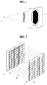
- FIG.1 is a view showing an X-ray radiography device using a cone beam X-ray that is mainly used in dental clinics.
- the X-ray radiography device generally includes an X-ray generator 1 and an X-ray detector 2 that face each other with a target 3 interposed between the X-ray generator 1 and the X-ray detector 2.
- X-rays generated from the X-ray generator 1 diffuse in a cone beam shape, transmit through the target 3 and are incident on the X-ray detector 2.
- X-ray detecting elements of the X-ray detector 2 generate electrical signals that are proportional to an amount of incident X-rays on the X-ray detecting elements. Therefore, the X-ray detector 2 may obtain an interior 2D projection image of the target 3 by image processing projection data that are obtained by the electrical signals and positional information of the X-ray detecting elements.
- a 3D computed tomography image of the target 3 may be obtained by reconstructing multi-directional projection data that are obtained by rotating the X-ray generator 1 and the X-ray detector 2.
- a source to detector distance (SDD) between the X-ray generator 1 and the X-ray detector 2 may be secured to radiograph a target 3 having more than a predetermined size.
- the X-ray detector 2 having a wider or larger surface than the target 3 is required.
- an object of the present invention is to provide an X-ray radiography device that is decreased in size, has a minimized X-ray detector area, and has reduced image distortion.
- an X-ray radiography device the device includes: an X-ray source including a plurality of X-ray emitting elements arranged in at least 2X2 pixel matrix on a planar surface or a curved surface and respectively emitting X-rays to a target; and an X-ray detector detecting the X-rays transmitted through the target.
- the X-ray detector may include a plurality of X-ray detecting elements arranged in an at least 2X2 pixel matrix on a planar surface or a curved surface to be mapped one-to-one or one-to-many to the X-ray source, and respectively to detect each of the X-rays transmitted through the target.
- the X-ray emitting elements may include cathodes of carbon nanotubes.
- the plurality of X-ray emitting elements and the plurality of X-ray detecting elements may be arranged on separate planar surfaces or on separate curved surfaces.
- the X-ray emitting elements and the X-ray detecting elements may be arranged to face each other with the target being interposed between the X-ray emitting elements and the X-ray detecting elements.
- the X-ray radiography device may further include a flexible bending part connecting the separate planar surfaces or the separate curved surfaces to each other.
- one of the plurality of X-ray emitting elements and the plurality of X-ray detecting elements may be arranged along a curved surface having an arc-shaped cross-section perpendicular to a vertical axis of the target to cover at least three sides of the target, and a remaining one of the plurality of X-ray emitting elements and the plurality of X-ray detecting elements may move with facing the target while being interposed between the target and the remaining one of the plurality of X-ray emitting elements and the plurality of X-ray detecting elements.
- the X-ray emitting elements and the X-ray detecting elements may be arranged on a same planar surface or a same curved surface.
- the X-ray emitting elements and the X-ray detecting elements may be arranged in a grid matrix to alternately dispose the X-ray emitting elements and the X-ray detecting elements in each column and each row, or in a stripe matrix to respectively dispose the X-ray emitting elements and the X-ray detecting elements are disposed in alternate columns or in alternate rows.
- planar surface or the curved surface may have flexibility.
- the X-ray emitting elements may sequentially emit the X-rays in a row or a column.
- the present invention has outstanding effects as follows.
- the X-ray radiography device provides an X-ray source including: a plurality of X-ray emitting elements, the X-ray emitting elements being arranged in a pixel matrix and respectively emitting X-rays to a part or the entirety of a target; and an X-ray detector including a plurality of X-ray detecting elements, the X-ray detecting elements being arranged in a pixel matrix, being mapped one-to-one or one-to-many to the X-ray emitting elements, and respectively detecting the X-rays transmitted through the part or the entirety of the target.
- the X-ray radiography device may obtain a 3D image without physically moving the X-ray source or the X-ray detector, or both of the X-ray source and the X-ray detector by arranging the X-ray emitting elements of the X-ray source and the X-ray detecting elements of the X-ray detector on the same or separate surfaces that are planar or curved surfaces.
- the X-ray radiography device provides effect of minimizing the size and simplifying the configuration thereof by simplifying a driving mechanism.
- FIG.2 is a schematic view showing an X-ray source 110 and an X-ray detector 120 of an X-ray radiograph device according to the present invention.
- the X-ray radiograph device may obtain a radiograph of a body, in particular, the device may be effectively used for dental clinics in which patient's head and mouth are used as a target, and include an X-ray source 110 and an X-ray detector 120.
- the X-ray source 110 emits X-rays and includes a plurality of X-ray emitting elements 111 that are arranged along a predetermined surface and respectively emit the X-rays.
- Each of the plurality of X-ray emitting elements 111 is an individual X-ray source.
- the plurality of X-ray emitting elements 111 is configured to include respective cathodes and anodes.
- the cathodes of field emission using nano-materials solve the excessive power consumption problem caused by overheating of cathodes and also improve the focus limitation of an electron beam with a small size compared to a conventional thermal electron X-ray source.
- nano-materials such as carbon nanotube (CNT)
- the plurality of the X-ray emitting elements 111 is arranged in a matrix on a predetermined surface.
- each of the X-ray emitting elements 111 becomes a unit pixel of the X-ray source 110, is arranged in N rows and M columns according to the size of a target, and emits X-rays to the target.
- the predetermined surface may be a planar surface or a curved surface.
- the X-ray source 110 including the X-ray emitting elements 111 arranged in a matrix configuration may emit an X-ray flux that transmits through a part or the entirety of a target, and the X-ray emitting elements 111 are arranged in an at least 2X2 matrix.
- an electrical switching means or a control program may drive the plurality of the X-ray emitting elements 111 at the same time, or, separately or sequentially drive the X-ray emitting elements 111 by a particular row or column.
- the X-ray detector 120 detects the X-rays emitted from the X-ray source 110, and includes a plurality of X-ray detecting elements 121 that face the X-ray emitting elements 111 with the target being interposed therebetween.
- the plurality of X-ray detecting elements 121 generates electrical signals that are respectively proportional to an amount of incident X-rays on the X-ray detecting elements 121.
- the X-ray detecting elements 121 may be image sensors.
- the plurality of X-ray detecting elements 121 may be arranged in a matrix of N rows and M columns along a predetermined surface.
- the predetermined surface may be a planar surface or a curved surface.
- the plurality of X-ray emitting elements 111 and the plurality X-ray detecting elements 121 are mapped one-to-one or one-to-many to each other. Therefore, the X-rays emitted from the X-ray emitting elements 111 are incident on at least one X-ray detecting element 121. It is preferable to arrange the X-ray detecting elements 121 in an at least 2X2 matrix.
- the X-ray detector 120 includes a signal processing part (not shown) that generates projection data about the target based on each electrical signals and positional information of the X-ray detecting elements 121.
- the X-ray emitting elements 111 of the X-ray source 110 are arranged in a pixel matrix configuration and emit the X-rays to the target, and the X-ray detecting elements 121 of the X-ray detector 120 are mapped one-to-one or one-to-many to the X-ray emitting elements 111 and detect the X-rays that transmitted through the target.
- an interior 2D projection image of the target may be obtained by image processing the projection data that are obtained based on each electrical signal and positional information of each X-ray detecting element 121.
- a 3D computed tomography image of the target may be obtained by reconstructing multi-directional projection data of the target.
- matrix configurations of the X-ray emitting elements 111 of the X-ray source 110 and the X-ray detecting elements 121 of the X-ray source 110 are adjusted such that X-ray fluxes that are respectively emitted from the X-ray emitting elements 111 and are transmitted through the target are maintained in parallel.
- the distance between the X-ray source 110 and the X-ray detector 120 may be minimized and the sizes of the X-ray source 110 and the X-ray detector 120 may also be minimized.
- the X-rays detected by the X-ray detecting elements 121 of the X-ray detector 120 actually appear that the X-rays are focused on the X-ray detecting elements 121 in parallel, thus, the resolution of the image can be raised and image distortion such as penumbra can be remarkably reduced.
- At least one collimator may be provided between the X-ray source 110 and the target and/or between the target and the X-ray detector 120 such that the X-ray emitting elements 111 and the X-ray detecting elements 121 are mapped one-to-one or one-to-many to each other.
- the collimator may have a grid configuration or a similar form.
- the X-ray emitting elements 111 and the X-ray detecting elements 121 of the X-ray radiography device according to the present invention may be arranged on separate planar surfaces or separate curved surfaces.
- the separate planar surfaces and the separate curved surfaces are separately described.
- the embodiments of the present invention will be described with reference to fig.2 and other drawings.
- the X-ray emitting elements 111 of the X-ray source 110 and the X-ray detecting elements 121 of the X-ray detector 120 of the X-ray radiography device according to the present invention are arranged on separate planar surfaces or on separate curved surfaces.
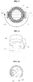
- FIGS. 3 and 4 are a top-plan view and a perspective view of an X-ray radiography device according to a first embodiment of the present invention.
- the X-ray radiography device includes the X-ray source 110, the X-ray detector 120, and a housing 130.
- the X-ray emitting elements 111 of the X-ray source 110 and the X-ray detecting elements 121 of the X-ray detector 120 are arranged on separate planar surfaces or on separate curved surfaces, and the housing 130 provides an accommodation space for a target.
- the housing 130 may be fixed on a supporter, or provided to be capable of moving across rows and having a cylindrical shape to encircle the target, for example, patient's head. Therefore, the height of the housing 130 may be adjusted according to an age or height of the target.
- the X-ray source 110 and the X-ray detector 120 may be provided inside the housing 130, or may be provided on the bottom of the housing 130, as shown in the FIG. 4 .
- the X-ray source 110 and the X-ray detector 120 may rotate along the housing 130 with the target being interposed therebetween.
- a 2D projection image of the target is obtained by using the X-ray source 110 and the X-ray detector 120
- a 3D computed tomography image may be also obtained by obtaining and reconstructing multi-directional projection data of the target that are obtained by rotating the X-ray source 110 and the X-ray detector 120.
- the X-ray radiography device of FIGS. 3 and 4 is shown such that the X-ray source 110 and the X-ray detector 120 are arranged on separate planar surfaces, but the X-ray source 110 and the X-ray detector 120 may be arranged on separate curved surfaces, and each surface may cover the target.
- a 3D computed tomography image may be obtained by arranging the X-ray emitting elements 111 of the X-ray source 110 and the X-ray detecting elements 121 of the X-ray detector 120 of the present invention on separate planar surfaces or separate curved surfaces, and without moving or rotating at least one planer surface or curved surface.
- FIGS. 5a to 5c are views showing an X-ray radiography device according to a second embodiment of the present invention.
- the X-ray radiography device according to the second embodiment of the present invention, the X-ray source 110 and the X-ray detector 120 are arranged on separate curved surfaces.
- a 3D computed tomography image may be obtained without moving or rotating the X-ray source 110 and the X-ray detector 120 while obtaining a 3D computed tomography image.
- the surface of the X-ray source 110 has an arc-shaped cross-section which is perpendicular to a vertical axis of the target such that the surface covers at least three sides of the target.
- the plurality of X-ray emitting elements 111 that respectively emit X-rays are arranged in a matrix inside the X-ray source 110.
- the X-ray detector 120 may move facing the target and a part of the X-ray source 110 while the X-ray detector 120 is interposed between the X-ray source 110 and the target, and the X-ray detecting elements 121 are arranged in a matrix inside the X-ray detector 120.
- the surface of the X-ray detector 120 may have a curved shape that corresponds to the inside of the X-ray source 110 and the radius thereof may be smaller than the X-ray source 110, and the surface of the X-ray detector 120 may move along the inside of the X-ray source 110.
- the X-ray detector 120 is arranged inside the X-ray source 110 that has the arc shape and covers at least three sides of the target, and the X-ray detector 120 may move along the inside of the X-ray source 110.
- a 2D projection image of the target may be obtained by the X-rays emitted from the X-ray emitting elements 111 that face the X-ray detector 120.
- a 3D computed tomography image may be obtained without moving the X-ray source 110 by rotating the X-ray detector 120 and sequentially driving the X-ray emitting elements 111 that are facing the X-ray detector 120.
- the surface of the X-ray detector 120 may have an arc-shaped cross-section which is perpendicular to the vertical axis of the target such that the surface covers at least three sides of the target.
- a 2D projection image and a 3D computed tomography image may be identically obtained by moving the X-ray source 110 along the inside of the X-ray detector 120.
- a 2D projection image may be obtained even though the target has a small size, or a wide area is not secured, and the X-ray source 110 and the X-ray detector 120 are arranged on separate planar surfaces or on separate curved surfaces.
- FIG. 6 is a view showing an X-ray radiography device according to a third embodiment of the present invention.
- the X-ray source 110 and the X-ray detector 120 are connected to each other by a flexible bending part 140, and the X-ray source 110 and the X-ray detector 120 are arranged on separate planar surfaces or on separate curved surfaces and connected to each other by the flexible bending part 140.
- the X-ray radiography device may obtain a 2D projection image of the target by properly bending the flexible bending part 140 such that the target is interposed between the X-ray source 110 and the X-ray detector 120 and receiving, by the X-ray detector 120, the X-rays emitted from the X-ray source 110 and having transmitted through the target.
- the X-ray radiography device is useful when the target has a small size, or when it is difficult for the radiography device to secure a wide area.
- the X-ray radiography device in dental clinics, is useful to radiograph multiple teeth that are inside the mouth. Thus, radiologists may easily perform the radiograph and patients may feel comfortable while radiographing.
- the X-ray emitting elements 111 of X-ray source 110 and the X-ray detecting elements 121 of the X-ray detector 120 are arranged on a single planer surface or on a single curved surface.
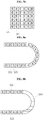
- FIGS. 7a and 7b are schematic views of the X-ray source 110 and the X-ray detector 120 capable of being applied to fourth to sixth embodiments of the present invention, and schematically show arrangement configurations of the X-ray emitting elements 111 and the X-ray detecting elements 121.
- the X-ray emitting elements 111 and the X-ray detecting elements 121 are arranged in a stripe matrix in which the X-ray emitting elements 111 and the X-ray detecting elements 121 are arranged in alternate columns or in alternate rows.
- the X-ray emitting elements 111 and the X-ray detecting elements 121 are arranged in a grid matrix in which the X-ray emitting elements 111 and the X-ray detecting elements 121 are alternately arranged in each column and each row of the grid matrix.
- FIG. 8a shows a schematic view of the X-ray radiography device of the fourth embodiment of the present invention, and the X-ray emitting elements 111 and the X-ray detecting elements 121 are arranged along the single surface having flexibility.
- the X-ray emitting elements 111 and the X-ray detecting elements 121 are arranged in the matrix of FIGS. 7a or 7b .
- the X-ray radiography device may obtain a 2D projection image of the target by properly bending the single surface such that the target is interposed between the X-ray source 110 and the X-ray detector 120, and receiving, by the X-ray detector 120, the X-rays emitted from the X-ray source 110 and transmitted through the target. Further, a 3D computed tomography image may be obtained by reconstructing multi-directional projection data that are obtained by rotating the X-ray source 110 and the X-ray detector 120 with the target being interposed therebetween.
- FIG. 8b shows a schematic view of the X-ray radiography device of the fifth embodiment of the present invention, two surfaces in which the X-ray emitting elements 111 and the X-ray detecting elements 121 are arranged on the surface are provided, the two surfaces are connected through the bending part 140 to face each other with the target being interposed therebetween.
- the X-ray emitting elements 111 and the X-ray detecting elements 121 are arranged on the two surfaces in the matrix of FIGS. 7a or 7b .
- the X-rays emitted from the X-ray emitting elements 111 of a first surface that is one of the two surfaces and having been transmitted through the target are detected by the X-ray detecting elements 121 of a second surface that is the other surface of the two surfaces, and the X-rays emitted from the X-ray emitting elements 111 of the second surface and having been transmitted through the target are detected by the X-ray detecting elements 121 of the first surface.
- a 2D projection image of the target may be obtained by using electrical signals and positional information of the X-ray detecting elements 121 of the first and second surfaces, and a 3D computed tomography image may be also obtained by reconstructing multi-directional data that are obtained by rotating the first and second surfaces with the target being interposed therebetween.
- FIG. 9 is a schematic view of the X-ray source and the X-ray detector of an X-ray radiography device according to a sixth embodiment of the present invention.
- the X-ray radiography device according to the fifth embodiment may obtain a 2D projection image and a 3D computed tomography image without rotating the X-ray source 110 and the X-ray detector 120 in which the X-ray emitting elements 111 of the X-ray source 110 and the X-ray detecting elements 121 of the X-ray detector 120 are arranged to cover at least three sides of the target.
- the X-ray emitting elements 111 and the X-ray detecting elements 121 are arranged on a single curved surface having a predetermined circumference.
- the X-ray emitting elements 111 of the X-ray source 110 and the X-ray detecting elements 121 of the X-ray detector 120 may be arranged in a stripe matrix of FIG. 7a or a grid matrix of FIG. 7b .
- a 2D projection image may be obtained by detecting the X-rays, respectively emitted from the X-ray emitting elements 111 and having been transmitted through the target, by the X-ray detecting elements 121 that face the X-ray emitting elements 111.
- multi-directional projection data are effectively obtained by detecting the X-rays emitted from the X-ray emitting elements 111 that are sequentially driven by a row or column through the X-ray detecting elements 121 facing the X-ray emitting elements 111, thus a 3D computed tomography image may be obtained without rotating the X-ray source 110 and the X-ray detector 120.
- FIG. 10 is a view showing an X-ray radiography device according to a sixth embodiment of the present invention.
- the X-ray emitting elements 111 of the X-ray source 110 and the X-ray detecting elements 121 of the X-ray detector 120 are arranged on a single planar surface or a curved surface.
- Compact design of the X-ray radiography device is achieved by reducing the size of the device. Meanwhile, the device may be portable by using a separate fixing part.
- the X-ray emitting elements 111 of the X-ray source 110 and the X-ray detecting elements 121 of the X-ray detector 120 are arranged on a single curved surface having a predetermined circumference.
- the X-ray emitting elements 111 and the X-ray detecting elements 121 may be arranged in a stripe matrix of FIG. 7a or in a grid matrix of FIG. 7b , and the single surface may be provided in a separate casing.
- the single curved surface, on which the X-ray emitting elements 111 of the X-ray source 110 and the X-ray detecting elements 121 of the X-ray detector 120 are arranged, is coupled to a fixing part 132 that is fixed on the head or the body of the target.
- the fixing part 132 provides a predetermined space part that accommodates the target, and includes an adjusting means 133 that is capable of adjusting the space part.
- the X-ray radiography device may have a compact size to be easily carried, obtain a 2D projection image by fixing the fixing part 132 to the target such as head, arm, leg, etc. and obtain a 3D computed tomography image without rotating the X-ray source 110 and the X-ray detector 120.
- the X-ray emitting elements 111 and the X-ray detecting elements 121 may be mapped one-to-one or one-to-many to each other.
- a 3D computed tomography image may be obtained by individually controlling the X-ray emitting elements 111 and by irradiating the X-rays in multiple directions toward the target.
- FIG. 11 is a schematic view of the X-ray source and the X-ray detector of an X-ray radiography device according to a seventh embodiment of the present invention.
- the X-ray radiography device is externally similar to the embodiment of FIG. 2 .
- the X-ray emitting elements 111 of the X-ray source 110 are mapped one-to-many to the X-ray detecting elements 121 of the X-ray detector 120.
- the X-ray emitting elements 111 sequentially irradiate X-rays while the X-ray emitting elements 111 of the X-ray source 110 are mapped one-to-many to the X-ray detecting elements 121 of the X-ray detector 120.
- the X-ray detector 120 detects the X-rays having been transmitted through the target in different directions and obtains multi-directional X-ray detecting results.
- a 3D computed tomography image may be obtained by reconstructing projection data that are obtained by X-ray detection results in each direction.
- a 3D computed tomography image may be obtained without rotating the X-ray source 110 and/or the X-ray detector 120, or by rotating the X-ray source 110 and/or the X-ray detector 120 at a minimum angle.
- the present invention may be applied to an X-ray radiography device that captures radiographs of patient's body.
Landscapes
- Health & Medical Sciences (AREA)
- Life Sciences & Earth Sciences (AREA)
- Medical Informatics (AREA)
- Engineering & Computer Science (AREA)
- Radiology & Medical Imaging (AREA)
- Biomedical Technology (AREA)
- Biophysics (AREA)
- Nuclear Medicine, Radiotherapy & Molecular Imaging (AREA)
- Optics & Photonics (AREA)
- Pathology (AREA)
- Physics & Mathematics (AREA)
- High Energy & Nuclear Physics (AREA)
- Heart & Thoracic Surgery (AREA)
- Molecular Biology (AREA)
- Surgery (AREA)
- Animal Behavior & Ethology (AREA)
- General Health & Medical Sciences (AREA)
- Public Health (AREA)
- Veterinary Medicine (AREA)
- Apparatus For Radiation Diagnosis (AREA)
Applications Claiming Priority (2)
| Application Number | Priority Date | Filing Date | Title |
|---|---|---|---|
| KR1020140014024A KR102234422B1 (ko) | 2014-02-07 | 2014-02-07 | 엑스선 촬영장치 |
| PCT/KR2015/001276 WO2015119466A1 (fr) | 2014-02-07 | 2015-02-09 | Dispositif d'imagerie à rayons x |
Publications (3)
| Publication Number | Publication Date |
|---|---|
| EP3103394A1 true EP3103394A1 (fr) | 2016-12-14 |
| EP3103394A4 EP3103394A4 (fr) | 2017-12-20 |
| EP3103394B1 EP3103394B1 (fr) | 2020-11-18 |
Family
ID=53778209
Family Applications (1)
| Application Number | Title | Priority Date | Filing Date |
|---|---|---|---|
| EP15746575.8A Active EP3103394B1 (fr) | 2014-02-07 | 2015-02-09 | Dispositif d'imagerie à rayons x |
Country Status (4)
| Country | Link |
|---|---|
| US (1) | US10165993B2 (fr) |
| EP (1) | EP3103394B1 (fr) |
| KR (1) | KR102234422B1 (fr) |
| WO (1) | WO2015119466A1 (fr) |
Cited By (2)
| Publication number | Priority date | Publication date | Assignee | Title |
|---|---|---|---|---|
| US11051771B2 (en) | 2014-06-17 | 2021-07-06 | Xintek, Inc. | Stationary intraoral tomosynthesis imaging systems, methods, and computer readable media for three dimensional dental imaging |
| US12004890B2 (en) | 2018-10-26 | 2024-06-11 | Surround Medical Systems, Inc. | Intraoral tomosynthesis X-ray imaging device, system, and method with interchangeable collimator |
Families Citing this family (4)
| Publication number | Priority date | Publication date | Assignee | Title |
|---|---|---|---|---|
| GB2531326B (en) * | 2014-10-16 | 2020-08-05 | Adaptix Ltd | An X-Ray emitter panel and a method of designing such an X-Ray emitter panel |
| JP7097819B2 (ja) * | 2016-05-13 | 2022-07-08 | コーニンクレッカ フィリップス エヌ ヴェ | 4dイメージングのためのマルチビームx線露光のためのシステム及び方法 |
| US10692184B2 (en) | 2018-07-05 | 2020-06-23 | SVXR, Inc. | Super-resolution X-ray imaging method and apparatus |
| US11489830B2 (en) | 2020-01-09 | 2022-11-01 | Kyndryl, Inc. | Source authentication of website content |
Family Cites Families (13)
| Publication number | Priority date | Publication date | Assignee | Title |
|---|---|---|---|---|
| DE2658533C2 (de) * | 1976-12-23 | 1987-02-26 | Siemens AG, 1000 Berlin und 8000 München | Vorrichtung zur Darstellung von Körperlängsschichten |
| US7082182B2 (en) * | 2000-10-06 | 2006-07-25 | The University Of North Carolina At Chapel Hill | Computed tomography system for imaging of human and small animal |
| US8837669B2 (en) * | 2003-04-25 | 2014-09-16 | Rapiscan Systems, Inc. | X-ray scanning system |
| US20050226364A1 (en) | 2003-11-26 | 2005-10-13 | General Electric Company | Rotational computed tomography system and method |
| US7280631B2 (en) * | 2003-11-26 | 2007-10-09 | General Electric Company | Stationary computed tomography system and method |
| JP2005288152A (ja) * | 2004-03-31 | 2005-10-20 | General Electric Co <Ge> | 回転コンピュータ断層撮影のシステム及び方法 |
| US20070237296A1 (en) * | 2004-09-13 | 2007-10-11 | Wyatt Jeffrey D | Decontamination using planar X-ray sources |
| JP5550209B2 (ja) * | 2007-12-25 | 2014-07-16 | キヤノン株式会社 | X線撮影装置 |
| WO2009115982A1 (fr) * | 2008-03-21 | 2009-09-24 | Koninklijke Philips Electronics N.V. | Dispositif de tomodensimétrie et procédé d'acquisition d'images par tomodensimétrie basés sur des microsources de rayons x réparties dans l'espace du type faisceau conique |
| JP4693884B2 (ja) * | 2008-09-18 | 2011-06-01 | キヤノン株式会社 | マルチx線撮影装置及びその制御方法 |
| DE102010040308A1 (de) * | 2010-09-07 | 2012-03-08 | Siemens Aktiengesellschaft | Röntgenaufnahmesystem und Verfahren zur Aufnahme eines Projektionsbildes |
| WO2012155201A1 (fr) | 2011-05-19 | 2012-11-22 | Newsouth Innovations Pty Ltd | Procédé et appareil pour générer une représentation d'une structure interne d'un objet |
| KR20140013403A (ko) * | 2012-07-23 | 2014-02-05 | 삼성전자주식회사 | 엑스선 촬영 장치 및 그 촬영 방법 |
-
2014
- 2014-02-07 KR KR1020140014024A patent/KR102234422B1/ko active Active
-
2015
- 2015-02-09 US US15/117,445 patent/US10165993B2/en active Active
- 2015-02-09 WO PCT/KR2015/001276 patent/WO2015119466A1/fr not_active Ceased
- 2015-02-09 EP EP15746575.8A patent/EP3103394B1/fr active Active
Cited By (3)
| Publication number | Priority date | Publication date | Assignee | Title |
|---|---|---|---|---|
| US11051771B2 (en) | 2014-06-17 | 2021-07-06 | Xintek, Inc. | Stationary intraoral tomosynthesis imaging systems, methods, and computer readable media for three dimensional dental imaging |
| US12016716B2 (en) | 2014-06-17 | 2024-06-25 | Surround Medical Systems, Inc. | Stationary intraoral tomosynthesis imaging systems, methods, and computer readable media for three dimensional dental imaging |
| US12004890B2 (en) | 2018-10-26 | 2024-06-11 | Surround Medical Systems, Inc. | Intraoral tomosynthesis X-ray imaging device, system, and method with interchangeable collimator |
Also Published As
| Publication number | Publication date |
|---|---|
| KR20150093362A (ko) | 2015-08-18 |
| US20160345919A1 (en) | 2016-12-01 |
| KR102234422B1 (ko) | 2021-03-31 |
| EP3103394B1 (fr) | 2020-11-18 |
| WO2015119466A1 (fr) | 2015-08-13 |
| US10165993B2 (en) | 2019-01-01 |
| EP3103394A4 (fr) | 2017-12-20 |
Similar Documents
| Publication | Publication Date | Title |
|---|---|---|
| US10165993B2 (en) | X-ray imagin device with distributed X-ray source | |
| KR102368907B1 (ko) | 구강 내 x선 촬영용 x선 발생장치 및 이를 포함하는 구강 내 x선 촬영 시스템 | |
| JP7633995B2 (ja) | スペクトルトモシンセシスシステムにおける幾何学的キャリブレーションマーカの検出 | |
| US9867582B2 (en) | Apparatus and method for controlling X-ray radiation field of X-ray imaging apparatus | |
| US9748069B2 (en) | X-ray generator and X-ray imaging apparatus including the same | |
| CN103943443B (zh) | 具有运动阳极或阴极的x射线源 | |
| US20220151576A1 (en) | Movable and static collimators and x-ray source arrangements for intraoral tomosynthesis | |
| EP3210538B1 (fr) | Appareil de génération de rayons x pour imagerie intra-orale à rayons x | |
| ES2848393T3 (es) | Fuente de rayos X | |
| US9380990B2 (en) | Apparatus and method for X-ray imaging of breast | |
| CN111031917B (zh) | X射线系统以及用于运行所述x射线系统的方法 | |
| EP2818113B1 (fr) | Appareil de photographie aux rayons X et son procédé de fonctionnement | |
| KR102139661B1 (ko) | 회전 가능한 시준기를 구비한 ct 시스템 | |
| CN111386077B (zh) | 一种x射线成像设备 | |
| EP2818112B1 (fr) | Appareil de photographie aux rayons X et son procédé de fonctionnement | |
| US9603575B2 (en) | X-ray imaging apparatus and method of operating the same | |
| JP2017056141A (ja) | 放射線検出器、検出器モジュール、及び医用画像診断装置 | |
| US20150003587A1 (en) | Apparatus and method for x-ray imaging | |
| JP6395373B2 (ja) | 放射線発生ユニットおよび放射線撮影装置 | |
| KR20180042572A (ko) | 가변형 디텍터 어레이를 갖는 엑스선 영상 촬영 장치 | |
| US10722196B2 (en) | Radiographic diagnosis apparatus, radiation detector and collimator | |
| US20260123898A1 (en) | X-ray system and method for operation thereof | |
| JP7483434B2 (ja) | X線診断装置、立体画像表示装置及び立体画像表示方法 | |
| JP2022081092A (ja) | X線ct装置、動画像生成方法、および撮影制御方法 | |
| KR102329046B1 (ko) | 구강 내 x선 촬영시스템과 촬영방법 그리고 이를 위한 가이드홀더 |
Legal Events
| Date | Code | Title | Description |
|---|---|---|---|
| STAA | Information on the status of an ep patent application or granted ep patent |
Free format text: STATUS: THE INTERNATIONAL PUBLICATION HAS BEEN MADE |
|
| PUAI | Public reference made under article 153(3) epc to a published international application that has entered the european phase |
Free format text: ORIGINAL CODE: 0009012 |
|
| STAA | Information on the status of an ep patent application or granted ep patent |
Free format text: STATUS: REQUEST FOR EXAMINATION WAS MADE |
|
| 17P | Request for examination filed |
Effective date: 20160907 |
|
| AK | Designated contracting states |
Kind code of ref document: A1 Designated state(s): AL AT BE BG CH CY CZ DE DK EE ES FI FR GB GR HR HU IE IS IT LI LT LU LV MC MK MT NL NO PL PT RO RS SE SI SK SM TR |
|
| AX | Request for extension of the european patent |
Extension state: BA ME |
|
| DAX | Request for extension of the european patent (deleted) | ||
| A4 | Supplementary search report drawn up and despatched |
Effective date: 20171120 |
|
| RIC1 | Information provided on ipc code assigned before grant |
Ipc: A61B 6/00 20060101AFI20171114BHEP |
|
| STAA | Information on the status of an ep patent application or granted ep patent |
Free format text: STATUS: EXAMINATION IS IN PROGRESS |
|
| 17Q | First examination report despatched |
Effective date: 20191014 |
|
| GRAP | Despatch of communication of intention to grant a patent |
Free format text: ORIGINAL CODE: EPIDOSNIGR1 |
|
| STAA | Information on the status of an ep patent application or granted ep patent |
Free format text: STATUS: GRANT OF PATENT IS INTENDED |
|
| INTG | Intention to grant announced |
Effective date: 20200724 |
|
| GRAS | Grant fee paid |
Free format text: ORIGINAL CODE: EPIDOSNIGR3 |
|
| GRAA | (expected) grant |
Free format text: ORIGINAL CODE: 0009210 |
|
| STAA | Information on the status of an ep patent application or granted ep patent |
Free format text: STATUS: THE PATENT HAS BEEN GRANTED |
|
| AK | Designated contracting states |
Kind code of ref document: B1 Designated state(s): AL AT BE BG CH CY CZ DE DK EE ES FI FR GB GR HR HU IE IS IT LI LT LU LV MC MK MT NL NO PL PT RO RS SE SI SK SM TR |
|
| REG | Reference to a national code |
Ref country code: GB Ref legal event code: FG4D |
|
| REG | Reference to a national code |
Ref country code: CH Ref legal event code: EP |
|
| REG | Reference to a national code |
Ref country code: IE Ref legal event code: FG4D |
|
| REG | Reference to a national code |
Ref country code: DE Ref legal event code: R096 Ref document number: 602015062173 Country of ref document: DE |
|
| REG | Reference to a national code |
Ref country code: AT Ref legal event code: REF Ref document number: 1334856 Country of ref document: AT Kind code of ref document: T Effective date: 20201215 |
|
| REG | Reference to a national code |
Ref country code: AT Ref legal event code: MK05 Ref document number: 1334856 Country of ref document: AT Kind code of ref document: T Effective date: 20201118 |
|
| REG | Reference to a national code |
Ref country code: NL Ref legal event code: MP Effective date: 20201118 |
|
| PG25 | Lapsed in a contracting state [announced via postgrant information from national office to epo] |
Ref country code: PT Free format text: LAPSE BECAUSE OF FAILURE TO SUBMIT A TRANSLATION OF THE DESCRIPTION OR TO PAY THE FEE WITHIN THE PRESCRIBED TIME-LIMIT Effective date: 20210318 Ref country code: RS Free format text: LAPSE BECAUSE OF FAILURE TO SUBMIT A TRANSLATION OF THE DESCRIPTION OR TO PAY THE FEE WITHIN THE PRESCRIBED TIME-LIMIT Effective date: 20201118 Ref country code: FI Free format text: LAPSE BECAUSE OF FAILURE TO SUBMIT A TRANSLATION OF THE DESCRIPTION OR TO PAY THE FEE WITHIN THE PRESCRIBED TIME-LIMIT Effective date: 20201118 Ref country code: NO Free format text: LAPSE BECAUSE OF FAILURE TO SUBMIT A TRANSLATION OF THE DESCRIPTION OR TO PAY THE FEE WITHIN THE PRESCRIBED TIME-LIMIT Effective date: 20210218 Ref country code: GR Free format text: LAPSE BECAUSE OF FAILURE TO SUBMIT A TRANSLATION OF THE DESCRIPTION OR TO PAY THE FEE WITHIN THE PRESCRIBED TIME-LIMIT Effective date: 20210219 |
|
| PG25 | Lapsed in a contracting state [announced via postgrant information from national office to epo] |
Ref country code: AT Free format text: LAPSE BECAUSE OF FAILURE TO SUBMIT A TRANSLATION OF THE DESCRIPTION OR TO PAY THE FEE WITHIN THE PRESCRIBED TIME-LIMIT Effective date: 20201118 Ref country code: BG Free format text: LAPSE BECAUSE OF FAILURE TO SUBMIT A TRANSLATION OF THE DESCRIPTION OR TO PAY THE FEE WITHIN THE PRESCRIBED TIME-LIMIT Effective date: 20210218 Ref country code: PL Free format text: LAPSE BECAUSE OF FAILURE TO SUBMIT A TRANSLATION OF THE DESCRIPTION OR TO PAY THE FEE WITHIN THE PRESCRIBED TIME-LIMIT Effective date: 20201118 Ref country code: LV Free format text: LAPSE BECAUSE OF FAILURE TO SUBMIT A TRANSLATION OF THE DESCRIPTION OR TO PAY THE FEE WITHIN THE PRESCRIBED TIME-LIMIT Effective date: 20201118 Ref country code: IS Free format text: LAPSE BECAUSE OF FAILURE TO SUBMIT A TRANSLATION OF THE DESCRIPTION OR TO PAY THE FEE WITHIN THE PRESCRIBED TIME-LIMIT Effective date: 20210318 Ref country code: SE Free format text: LAPSE BECAUSE OF FAILURE TO SUBMIT A TRANSLATION OF THE DESCRIPTION OR TO PAY THE FEE WITHIN THE PRESCRIBED TIME-LIMIT Effective date: 20201118 |
|
| REG | Reference to a national code |
Ref country code: LT Ref legal event code: MG9D |
|
| PG25 | Lapsed in a contracting state [announced via postgrant information from national office to epo] |
Ref country code: HR Free format text: LAPSE BECAUSE OF FAILURE TO SUBMIT A TRANSLATION OF THE DESCRIPTION OR TO PAY THE FEE WITHIN THE PRESCRIBED TIME-LIMIT Effective date: 20201118 |
|
| PG25 | Lapsed in a contracting state [announced via postgrant information from national office to epo] |
Ref country code: RO Free format text: LAPSE BECAUSE OF FAILURE TO SUBMIT A TRANSLATION OF THE DESCRIPTION OR TO PAY THE FEE WITHIN THE PRESCRIBED TIME-LIMIT Effective date: 20201118 Ref country code: SK Free format text: LAPSE BECAUSE OF FAILURE TO SUBMIT A TRANSLATION OF THE DESCRIPTION OR TO PAY THE FEE WITHIN THE PRESCRIBED TIME-LIMIT Effective date: 20201118 Ref country code: LT Free format text: LAPSE BECAUSE OF FAILURE TO SUBMIT A TRANSLATION OF THE DESCRIPTION OR TO PAY THE FEE WITHIN THE PRESCRIBED TIME-LIMIT Effective date: 20201118 Ref country code: SM Free format text: LAPSE BECAUSE OF FAILURE TO SUBMIT A TRANSLATION OF THE DESCRIPTION OR TO PAY THE FEE WITHIN THE PRESCRIBED TIME-LIMIT Effective date: 20201118 Ref country code: CZ Free format text: LAPSE BECAUSE OF FAILURE TO SUBMIT A TRANSLATION OF THE DESCRIPTION OR TO PAY THE FEE WITHIN THE PRESCRIBED TIME-LIMIT Effective date: 20201118 Ref country code: EE Free format text: LAPSE BECAUSE OF FAILURE TO SUBMIT A TRANSLATION OF THE DESCRIPTION OR TO PAY THE FEE WITHIN THE PRESCRIBED TIME-LIMIT Effective date: 20201118 |
|
| REG | Reference to a national code |
Ref country code: DE Ref legal event code: R097 Ref document number: 602015062173 Country of ref document: DE |
|
| PG25 | Lapsed in a contracting state [announced via postgrant information from national office to epo] |
Ref country code: DK Free format text: LAPSE BECAUSE OF FAILURE TO SUBMIT A TRANSLATION OF THE DESCRIPTION OR TO PAY THE FEE WITHIN THE PRESCRIBED TIME-LIMIT Effective date: 20201118 |
|
| PLBE | No opposition filed within time limit |
Free format text: ORIGINAL CODE: 0009261 |
|
| STAA | Information on the status of an ep patent application or granted ep patent |
Free format text: STATUS: NO OPPOSITION FILED WITHIN TIME LIMIT |
|
| PG25 | Lapsed in a contracting state [announced via postgrant information from national office to epo] |
Ref country code: MC Free format text: LAPSE BECAUSE OF FAILURE TO SUBMIT A TRANSLATION OF THE DESCRIPTION OR TO PAY THE FEE WITHIN THE PRESCRIBED TIME-LIMIT Effective date: 20201118 |
|
| 26N | No opposition filed |
Effective date: 20210819 |
|
| REG | Reference to a national code |
Ref country code: BE Ref legal event code: MM Effective date: 20210228 |
|
| PG25 | Lapsed in a contracting state [announced via postgrant information from national office to epo] |
Ref country code: NL Free format text: LAPSE BECAUSE OF FAILURE TO SUBMIT A TRANSLATION OF THE DESCRIPTION OR TO PAY THE FEE WITHIN THE PRESCRIBED TIME-LIMIT Effective date: 20201118 Ref country code: LU Free format text: LAPSE BECAUSE OF NON-PAYMENT OF DUE FEES Effective date: 20210209 Ref country code: LI Free format text: LAPSE BECAUSE OF NON-PAYMENT OF DUE FEES Effective date: 20210228 Ref country code: IT Free format text: LAPSE BECAUSE OF FAILURE TO SUBMIT A TRANSLATION OF THE DESCRIPTION OR TO PAY THE FEE WITHIN THE PRESCRIBED TIME-LIMIT Effective date: 20201118 Ref country code: AL Free format text: LAPSE BECAUSE OF FAILURE TO SUBMIT A TRANSLATION OF THE DESCRIPTION OR TO PAY THE FEE WITHIN THE PRESCRIBED TIME-LIMIT Effective date: 20201118 Ref country code: CH Free format text: LAPSE BECAUSE OF NON-PAYMENT OF DUE FEES Effective date: 20210228 |
|
| PG25 | Lapsed in a contracting state [announced via postgrant information from national office to epo] |
Ref country code: SI Free format text: LAPSE BECAUSE OF FAILURE TO SUBMIT A TRANSLATION OF THE DESCRIPTION OR TO PAY THE FEE WITHIN THE PRESCRIBED TIME-LIMIT Effective date: 20201118 Ref country code: ES Free format text: LAPSE BECAUSE OF FAILURE TO SUBMIT A TRANSLATION OF THE DESCRIPTION OR TO PAY THE FEE WITHIN THE PRESCRIBED TIME-LIMIT Effective date: 20201118 |
|
| PG25 | Lapsed in a contracting state [announced via postgrant information from national office to epo] |
Ref country code: IE Free format text: LAPSE BECAUSE OF NON-PAYMENT OF DUE FEES Effective date: 20210209 |
|
| PG25 | Lapsed in a contracting state [announced via postgrant information from national office to epo] |
Ref country code: IS Free format text: LAPSE BECAUSE OF FAILURE TO SUBMIT A TRANSLATION OF THE DESCRIPTION OR TO PAY THE FEE WITHIN THE PRESCRIBED TIME-LIMIT Effective date: 20210318 |
|
| PG25 | Lapsed in a contracting state [announced via postgrant information from national office to epo] |
Ref country code: BE Free format text: LAPSE BECAUSE OF NON-PAYMENT OF DUE FEES Effective date: 20210228 |
|
| PG25 | Lapsed in a contracting state [announced via postgrant information from national office to epo] |
Ref country code: HU Free format text: LAPSE BECAUSE OF FAILURE TO SUBMIT A TRANSLATION OF THE DESCRIPTION OR TO PAY THE FEE WITHIN THE PRESCRIBED TIME-LIMIT; INVALID AB INITIO Effective date: 20150209 |
|
| PG25 | Lapsed in a contracting state [announced via postgrant information from national office to epo] |
Ref country code: CY Free format text: LAPSE BECAUSE OF FAILURE TO SUBMIT A TRANSLATION OF THE DESCRIPTION OR TO PAY THE FEE WITHIN THE PRESCRIBED TIME-LIMIT Effective date: 20201118 |
|
| P01 | Opt-out of the competence of the unified patent court (upc) registered |
Effective date: 20230525 |
|
| PG25 | Lapsed in a contracting state [announced via postgrant information from national office to epo] |
Ref country code: MK Free format text: LAPSE BECAUSE OF FAILURE TO SUBMIT A TRANSLATION OF THE DESCRIPTION OR TO PAY THE FEE WITHIN THE PRESCRIBED TIME-LIMIT Effective date: 20201118 |
|
| PG25 | Lapsed in a contracting state [announced via postgrant information from national office to epo] |
Ref country code: TR Free format text: LAPSE BECAUSE OF FAILURE TO SUBMIT A TRANSLATION OF THE DESCRIPTION OR TO PAY THE FEE WITHIN THE PRESCRIBED TIME-LIMIT Effective date: 20201118 |
|
| PG25 | Lapsed in a contracting state [announced via postgrant information from national office to epo] |
Ref country code: MT Free format text: LAPSE BECAUSE OF FAILURE TO SUBMIT A TRANSLATION OF THE DESCRIPTION OR TO PAY THE FEE WITHIN THE PRESCRIBED TIME-LIMIT Effective date: 20201118 |
|
| PGFP | Annual fee paid to national office [announced via postgrant information from national office to epo] |
Ref country code: DE Payment date: 20250106 Year of fee payment: 11 |
|
| PGFP | Annual fee paid to national office [announced via postgrant information from national office to epo] |
Ref country code: FR Payment date: 20250107 Year of fee payment: 11 |
|
| PGFP | Annual fee paid to national office [announced via postgrant information from national office to epo] |
Ref country code: GB Payment date: 20250106 Year of fee payment: 11 |