EP3103587B1 - Machine d'ebavurage pour des pieces metalliques usinees - Google Patents
Machine d'ebavurage pour des pieces metalliques usinees Download PDFInfo
- Publication number
- EP3103587B1 EP3103587B1 EP16000170.7A EP16000170A EP3103587B1 EP 3103587 B1 EP3103587 B1 EP 3103587B1 EP 16000170 A EP16000170 A EP 16000170A EP 3103587 B1 EP3103587 B1 EP 3103587B1
- Authority
- EP
- European Patent Office
- Prior art keywords
- shore
- belt
- deburring machine
- machine according
- contact roller
- Prior art date
- Legal status (The legal status is an assumption and is not a legal conclusion. Google has not performed a legal analysis and makes no representation as to the accuracy of the status listed.)
- Active
Links
Images

Classifications
-
- B—PERFORMING OPERATIONS; TRANSPORTING
- B24—GRINDING; POLISHING
- B24B—MACHINES, DEVICES, OR PROCESSES FOR GRINDING OR POLISHING; DRESSING OR CONDITIONING OF ABRADING SURFACES; FEEDING OF GRINDING, POLISHING, OR LAPPING AGENTS
- B24B21/00—Machines or devices using grinding or polishing belts; Accessories therefor
- B24B21/04—Machines or devices using grinding or polishing belts; Accessories therefor for grinding plane surfaces
- B24B21/06—Machines or devices using grinding or polishing belts; Accessories therefor for grinding plane surfaces involving members with limited contact area pressing the belt against the work, e.g. shoes sweeping across the whole area to be ground
- B24B21/08—Pressure shoes; Pressure members, e.g. backing belts
-
- B—PERFORMING OPERATIONS; TRANSPORTING
- B24—GRINDING; POLISHING
- B24B—MACHINES, DEVICES, OR PROCESSES FOR GRINDING OR POLISHING; DRESSING OR CONDITIONING OF ABRADING SURFACES; FEEDING OF GRINDING, POLISHING, OR LAPPING AGENTS
- B24B21/00—Machines or devices using grinding or polishing belts; Accessories therefor
- B24B21/002—Machines or devices using grinding or polishing belts; Accessories therefor for grinding edges or bevels
-
- B—PERFORMING OPERATIONS; TRANSPORTING
- B24—GRINDING; POLISHING
- B24B—MACHINES, DEVICES, OR PROCESSES FOR GRINDING OR POLISHING; DRESSING OR CONDITIONING OF ABRADING SURFACES; FEEDING OF GRINDING, POLISHING, OR LAPPING AGENTS
- B24B21/00—Machines or devices using grinding or polishing belts; Accessories therefor
- B24B21/04—Machines or devices using grinding or polishing belts; Accessories therefor for grinding plane surfaces
- B24B21/12—Machines or devices using grinding or polishing belts; Accessories therefor for grinding plane surfaces involving a contact wheel or roller pressing the belt against the work
Definitions
- the present invention relates to deburring machines for deburring metal workpieces according to the preambles of claims 1 and 3.
- a deburring machine for deburring of metal workpieces known, with a rotating about its longitudinal axis contact roller made of steel.
- On the outside of the contact roller is a soft covering made from up to 30 mm thick rubber coating vulcanized.
- Around this contact roller around an endless revolving sanding belt is provided on the outside of the actual abrasive is attached.
- This abrasive belt is not attached to the contact roller, but is held circumferentially on the contact roller and a second roller and clamped so that the drive of the abrasive belt can be done for example via the contact roller.
- the endless rotating abrasive belt is stretched so tight that no slip, or at least no appreciable, arises between the contact roller and the abrasive belt.
- the contact pressure at other locations, in particular on surfaces of the workpiece is correspondingly lower and the removal on the surface correspondingly lower. That is also wanted, because the workpiece should be deburred.
- Such hard contact rollers are advantageously used for workpieces that were made by laser or water jet technology, because these workpieces are comparatively thick over the entire workpiece surface.
- the workpiece may be warped due to thermal influences.
- the abrasive belt must be made yielding during deburring, so that the grinding belt can follow the contour of the workpiece at least partially and the machining of the surface of the workpiece is reduced to a minimum, because an unnecessary processing of the workpiece, in particular its surface requires one high power requirement of the deburring machine, leading to high wear of the grinding belt and has a high thermal stress on the workpiece result, which in extreme cases can lead to further distortion of the workpiece.
- the film In order to achieve the hardness required for the respective workpiece, the film must be changed together with the grinding arc at a workpiece change, which is very expensive. In the event that another compliance with the new workpiece is required, even another contact roller with a different coating must be used, which is also very expensive. Likewise, the grinding arc change designed as very expensive.
- a contact disc for a belt grinding machine is known, on the contact roller a flexible work cushion is attached.
- This work cushion is surrounded by an abrasion-resistant, closed, flexible but non-stretchable material.
- This jacket formed of cork, polyamide fiber, metal fabric or the like may be in one piece or consist of several different layers.
- Such a contact disk is suitable for a particular application.
- a different hardness must be realized.
- the shell must be changed at a workpiece change, which is very expensive.
- another compliance with the new workpiece is required, even another contact roller with a different coating must be used, which is also very expensive.
- the present invention seeks to provide a deburring machine of the type mentioned above with a large compliance range at sufficient for deburring back pressure on the ridge, their handling is much easier.
- a deburring machine designed according to this technical teaching has the advantage that a comparatively high backpressure is built up on the ridge by the peripheral pressure band present in addition to the revolving grinding belt, in particular if this has a higher hardness than the resilient lining, in order to grind it off effectively. This allows the use of a softer coating, so that the compliance is increased, for example, better compensate for workpiece irregularities.
- Another advantage is that due to the comparatively hard pressure belt and the associated back pressure on the ridge a Damage to the sanding belt is avoided by sharp or protruding burrs.
- a very particular advantage is that for the exchange of the printing tape only the tension roller of the sanding belt, possibly even the tensioning device of the printing tape, need to be solved before the print tape can be removed and replaced by another. A removal of the heavy contact roller as in the DE 32 38 624 A1 not necessary. Thus, the printing tape can be replaced in a simple manner and replaced by a pressure belt of different hardness.
- the printing tape is stretched over its own tensioning device. This has the advantage that the printing tape can be stretched independently of the sanding belt, with the result that both the printing belt and the sanding belt are optimally tensioned in order to avoid slippage on the contact roller.
- the printing tape is tensioned so that the printing tape during the grinding process exerts a contact pressure on the pad roller located on the pad.
- the printing tape is at least as wide designed as the abrasive belt. This has the advantage that the desired back pressure over the entire width of the sanding belt is available.
- a pressure belt also means that a softer surface can be used, which has a high compliance, while the built-up by the pressure belt in conjunction with the sanding belt back pressure allows sufficient removal of the chip or burr without the sanding belt is damaged. Consequently, even a covering of a foam, in particular a technical cell foam, preferably of ethylene-propylene-diene rubber (EPDM), natural rubber, sponge rubber or sponge rubber with a hardness of 5 ° Shore to 25 ° Shore can be used without the abrasive belt Damage decreases, so that loops of up to 15 mm, in extreme cases even 20 mm, can be achieved during grinding.
- EPDM ethylene-propylene-diene rubber
- the contact roller has a diameter of 250 mm to 600 mm, preferably 400 mm. At present, contact rolls with a diameter of 180 mm are common. Such an enlarged contact roller has the advantage of enlarging the grinding surface on the burr, with the result that the burr is correspondingly longer machined and thus reliable removal of the burr and even a rounding of the edge is achieved.
- the pressure band has a structured surface on its side facing the lining of the contact roller.
- this structured surface has a structural depth of 0.1 mm to 2 mm, this has the advantage that protruding parts of the structured surface press into the comparatively soft coating and thus between the pressure band and the contact roller forms a positive fit, so that a good power transmission from the contact roller on the printing tape is carried out and thus the slip is minimized.
- a resilient covering with an average hardness of between 60 ° Shore and 70 ° Shore, preferably 65 ° Shore, is provided on the contact roller while the pressure band 5 "is constructed in three layers, with an inner layer (facing the contact roller) a fabric tape receiving the tensile forces, having a middle layer of a soft resilient covering with a hardness of 5 ° Shore to 25 ° Shore, preferably 25 ° Shore, and an outer layer (facing the abrasive tape) of a harder layer with 80 ° Shore until 100 ° Shore, preferably 90 ° Shore
- Another advantage is that after removal of the printing tape a contact roller with an average hardness of about 65 ° Shore is available, with which then a microsection can be created, which is not possible with a soft system. Thus, different operations can be completed on one and the same Entgratungsmaschine, which significantly increases the application of the Entratungsmaschine.
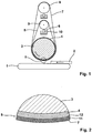
- FIG. 1 and 2 is a schematic representation of a first preferred embodiment of a deburring machine according to the invention shown.
- This deburring machine comprises a revolving conveyor belt 1 for transporting a workpiece 2, and a preferably electrically driven in a clockwise contact roller 3, on the surface of a soft EPDM formed soft and thus resilient coating 4 is applied, said resilient lining 4 is about 20 mm thick.
- Around the contact roller 3 around an endlessly circulating pressure belt 5 is provided, which is stretched over a tensioning device 6.
- To the contact roller 3 and the pressure belt 5 around an endless revolving belt 7 is provided, which is stretched over a tension roller 8.
- the tensioning device 6 comprises a roller 9 which is aligned coaxially with the contact roller 3 and which is tensioned by known spring mechanisms 10. Analogously, the tension roller 8 is constructed.
- the pressure belt 5 extends around the contact roller 3 on the one hand and on the other hand around the roller 9, the tensioning device 6 moving the roller 9 in order to tension the pressure belt 5.
- the covering 4 made of EPDM on the contact roller 3 has a thickness of approximately 20 mm and has a hardness of 15 ° Shore. It would also be conceivable to provide the coating with a hardness of only 5 ° Shore or up to 25 ° Shore.
- the thickness of the covering can vary between 5 mm and 50 mm.
- the printing tape 5 is constructed in two layers and has on its side facing the sanding belt 7, a comparatively hard layer 11 made of PVC, while the contact roller 3 facing inner side of the printing tape 5 is formed of a tensile fabric 12 having a textured surface.
- the hardness of the PVC layer 11 is approximately 5.33 times higher than the hardness of the lining 4 and is 80 ° Shore. In other embodiments, in particular with a hardness of the coating of 5 ° Shore, the PVC layer may also be 16 times harder.
- the structured surface of the fabric strip 12 of the printing tape 5 is at least partially pressed into the lining 4, so that a positive force transmission of the electrically driven contact roller 3 on the printing tape 5 takes place via this positive connection.
- the circulating around the pressure belt 5 sanding belt 7 is tensioned on the tension roller 8 so that the slip between the pressure belt 5 and the sanding belt 7 is reduced to a minimum, so that the electrically driven contact roller 3, the grinding belt 7 drives reliably and virtually without slippage.
- the contact roller 3 is adjusted so that the lowest point of the grinding belt 7 is below the upper edge of the workpiece 2. If the workpiece 2 now passes under the contact roller 3, the grinding belt 7, supported by the pressure belt 5 and the lining 4, exerts a force on the ridge projecting from the workpiece 2, not shown here, and wipes it off. Because the contact roller 3 has a diameter of 400 mm, a comparatively long processing time is available, so that the burr is reliably removed. In the event that the workpiece has unevenness or distortion, due to the soft and 20 mm thick coating 4, the grinding belt machine is capable of yielding a few mm, in particular up to 10 mm, in order to follow the contour of the workpiece. Due to the comparatively hard PVC layer 11 of the printing tape 5, a sufficiently high back pressure is built up on the ridge of the workpiece 2, so that the burr does not damage the sanding belt 7.
- the use of a thicker and harder pressure belt with a lower clamping pressure on the printing belt can increase the grinding pressure on the burr and at the same time preserve the flexibility to compensate for workpiece tolerances.
- a resilient covering 4 with a somewhat higher hardness of 60 ° Shore to 70 ° Shore, preferably 65 ° Shore is used. This can be created on the workpiece 2, a different grinding pattern than with the soft coating with 15 ° Shore.
- a pressure band is provided between the contact roller and the tension roller on the one hand and the abrasive belt on the other hand, wherein both the pressure belt, and the sanding belt are tensioned by the like tensioner.
- the pressure belt leads to an increased back pressure on the ridge and allows the use of a softer surface with the advantage of a higher compliance, at the same time easy to handle when changing the pressure belt and / or the sanding belt.
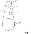
- Fig. 3 shows a second embodiment of a Entgratungsmaschine invention, which differs from the in the Fig. 1 and 2 illustrated first embodiment differs in that the pressure belt 5 ' is guided both to the contact roller 3 ', and about the tension roller 8' and that the tensioning device 6 'acts on the pressure belt 5' from the outside.
- the advantages described for the aforementioned embodiments apply to the in Fig. 3 described embodiment in an analogous manner.
- the sanding belt machine described here combines the advantage of a high compliance with high back pressure with the advantage that the hardness of the contact roller can be adjusted easily and quickly, at least without the contact roller needs to be changed.
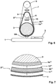
- a third embodiment of a deburring machine according to the invention is shown, which differs from the in the Fig. 1 and 2 only differs in that in the third embodiment, the resilient covering instead of the contact roller 3 is now attached to the pressure belt 5 "Again, the resilient coating either soft with a Shore hardness between 5 ° and 25 ° Shore or medium hard with Shore hardness between 60 ° and 70 ° Shore can be used.
- the resilient covering of the middle layer 4 may be formed of EPDM, PVC, PU, rubber or sponge rubber.
- a fourth, preferred embodiment is shown, which differs from the previous embodiments in that on the contact roller 3 a resilient covering 4a '"is provided, while the pressure belt 5"', analogous to the pressure belt 5 "according to the third embodiment, three-layered is, with a soft middle layer 4b "'.
- resilient pad 4a '" attached to the contact roller 3 resilient pad 4a '" has an average hardness of 60 ° to 70 ° Shore preferably 65 ° Shore, while the about 20 mm thick center layer 4b'" of the printing tape 5 "'is kept soft with a hardness of 5 ° to 25 ° Shore, preferably 25 ° Shore
- the inner layer 12 '" is made of a tensile fabric tape with a textured surface and the outer layer 11'" is made of a PVC having a Shore hardness of about 90 ° Shore.
Landscapes
- Engineering & Computer Science (AREA)
- Mechanical Engineering (AREA)
- Finish Polishing, Edge Sharpening, And Grinding By Specific Grinding Devices (AREA)
Claims (14)
- Machine d'ébavurage pour ébavurer des pièces métalliques avec une bande abrasive (7, 7') circulant sans fin, avec un rouleau de contact (3) pour presser la bande abrasive (7, 7') contre la pièce (2), où le rouleau de contact (3) est enrobé d'un revêtement souple (4, 4a"'), et avec un rouleau de tension (8) pour tendre la bande abrasive (7, 7'),
caractérisée en ce que
une bande de pression (5, 5', 5", 5"') circulant sans fin autour du rouleau de contact (3) et d'un second rouleau (9) est prévue entre le rouleau de contact (3) et la bande abrasive (7, 7'). - Machine d'ébavurage selon la revendication 1,
caractérisée en ce que
la bande de pression (5, 5') est formée de manière à être plus dure que le revêtement souple (4) du rouleau de contact (3), en particulier en ce que la dureté de la bande de pression (5) est plus élevée d'un facteur 2 à 10, de préférence d'un facteur 3 à 6, que la dureté du revêtement souple (4). - Machine d'ébavurage pour ébavurer des pièces métalliques avec une bande abrasive (7) circulant sans fin, avec un rouleau de contact (3) pour presser la bande abrasive (7) contre la pièce (2) et avec un rouleau de tension (8) pour tendre la bande abrasive (7),
caractérisée en ce que
une bande de pression (5", 5"') circulant sans fin autour du rouleau de contact (3) et d'un second rouleau (9) est prévue entre le rouleau de contact (3) et la bande abrasive (7) et que la bande de pression (5", 5"') comporte une revêtement souple. - Machine d'ébavurage selon l'une des revendications précédentes,
caractérisée en ce que
la bande de pression (5", 5"') est formée d'au moins trois couches, avec une première couche intérieure résistante à la traction (12", 12"'), avec une couche médiane (4", 4b"') faite d'un revêtement souple et mou et avec une couche extérieure (11 ", 11"') plus dure. - Machine d'ébavurage selon l'une des revendications précédentes,
caractérisée en ce que
le revêtement souple (4) a une dureté comprise entre 5° Shore et 25° Shore, de préférence de 20° Shore. - Machine d'ébavurage selon la revendication 4,
caractérisée en ce que
la couche médiane (4") a une dureté comprise entre 5° Shore et 25° Shore, de préférence de 20° Shore. - Machine d'ébavurage selon l'une des revendications précédentes,
caractérisée en ce que
le revêtement souple (4a"') a une dureté comprise entre 60° Shore et 70° Shore, de préférence de 65° Shore. - Machine d'ébavurage selon la revendication 4,
caractérisé en ce que
la couche médiane (4b"') a une dureté comprise entre 5° Shore et 25° Shore, de préférence de 20° Shore. - Machine d'ébavurage selon l'une des revendications précédentes,
caractérisée en ce que
la couche souple (4, 4a"') et/ou la couche médiane (4", 4b"') est formée d'une mousse, en particulier d'une mousse alvéolaire technique, de préférence en caoutchouc éthylène-propylène-diène (EPDM), de caoutchouc naturel, de caoutchouc mousse ou de caoutchouc spongieux. - Machine d'ébavurage selon l'une des revendications précédentes,
caractérisée en ce que
la bande de pression (5, 5', 5"') est tendue de telle manière que la bande de pression (5, 5', 5"') exerce une pression de contact sur le revêtement souple (4', 4a"') pendant le processus de ponçage. - Machine d'ébavurage selon l'une des revendications précédentes,
caractérisée en ce que
la bande de pression (5, 5', 5", 5"') est réalisée de manière à être au moins aussi large que la bande abrasive (6). - Machine d'ébavurage selon l'une des revendications précédentes,
caractérisée en ce que
la bande de pression (5, 5', 5", 5"') comporte une surface structurée sur son côté faisant face au rouleau de contact (3). - Machine d'ébavurage selon la revendication 12,
caractérisée en ce que
la surface structurée a une profondeur de structure de 0,1 mm à 2 mm. - Machine d'ébavurage selon l'une des revendications 12 ou 13,
caractérisée en ce que
la surface structurée comporte des reliefs, en particulier des protubérances et/ou des creux, en particulier des sillons.
Priority Applications (1)
| Application Number | Priority Date | Filing Date | Title |
|---|---|---|---|
| US15/072,447 US20160325395A1 (en) | 2015-05-07 | 2016-03-17 | Deburring Machine for Deburring Metal Work Pieces |
Applications Claiming Priority (1)
| Application Number | Priority Date | Filing Date | Title |
|---|---|---|---|
| DE102015005915.7A DE102015005915A1 (de) | 2015-05-07 | 2015-05-07 | Entgratungsmaschine zum Entgraten von metallenen Werkstücken |
Publications (2)
| Publication Number | Publication Date |
|---|---|
| EP3103587A1 EP3103587A1 (fr) | 2016-12-14 |
| EP3103587B1 true EP3103587B1 (fr) | 2017-06-14 |
Family
ID=55236158
Family Applications (1)
| Application Number | Title | Priority Date | Filing Date |
|---|---|---|---|
| EP16000170.7A Active EP3103587B1 (fr) | 2015-05-07 | 2016-01-25 | Machine d'ebavurage pour des pieces metalliques usinees |
Country Status (3)
| Country | Link |
|---|---|
| EP (1) | EP3103587B1 (fr) |
| DE (1) | DE102015005915A1 (fr) |
| PT (1) | PT3103587T (fr) |
Families Citing this family (2)
| Publication number | Priority date | Publication date | Assignee | Title |
|---|---|---|---|---|
| CN111571349A (zh) * | 2020-04-28 | 2020-08-25 | 青岛迪普瑞机械有限公司 | 板材干式磨砂去毛刺机 |
| CN114800188B (zh) * | 2022-04-22 | 2023-07-18 | 浙江亚特电器股份有限公司 | 一种可快速拆装的电动砂带机 |
Family Cites Families (6)
| Publication number | Priority date | Publication date | Assignee | Title |
|---|---|---|---|---|
| DE1042416B (de) * | 1954-03-06 | 1958-10-30 | C Hilzinger Thum Fa | Kontaktscheibe fuer Bandschleifmaschinen |
| DD132181B1 (de) * | 1977-05-26 | 1981-07-29 | Juergen Kallenbach | Bandschleifverfahren zum abtragen des schmiedegrates an rohlingen fuer ringschluessel |
| DE3020393A1 (de) * | 1980-05-29 | 1982-01-28 | Friedr. August Picard KG, 5630 Remscheid | Vorrichtung zum bandschleifen |
| DE3238624A1 (de) | 1982-10-19 | 1984-04-19 | Paul Dipl.-Ing. 6925 Eschelbronn Ernst Jun. | Schleifwalze fuer eine blechentgratungsmaschine |
| DE10342134B4 (de) * | 2003-09-12 | 2009-09-03 | Thielenhaus Technologies Gmbh | Verfahren und Vorrichtung zur Finishbearbeitung von Kurbel- und Nockenwellen |
| DE202005014430U1 (de) * | 2005-09-12 | 2005-11-24 | Lissmac Maschinenbau Und Diamantwerkzeuge Gmbh | Vorrichtung zum Bearbeiten eines Werkstücks |
-
2015
- 2015-05-07 DE DE102015005915.7A patent/DE102015005915A1/de not_active Withdrawn
-
2016
- 2016-01-25 PT PT160001707T patent/PT3103587T/pt unknown
- 2016-01-25 EP EP16000170.7A patent/EP3103587B1/fr active Active
Non-Patent Citations (1)
| Title |
|---|
| None * |
Also Published As
| Publication number | Publication date |
|---|---|
| EP3103587A1 (fr) | 2016-12-14 |
| PT3103587T (pt) | 2017-09-05 |
| DE102015005915A1 (de) | 2016-11-10 |
Similar Documents
| Publication | Publication Date | Title |
|---|---|---|
| EP2212058B2 (fr) | Dispositif de pression d'éléments coupants, dispositif et procédé de finition de surfaces périphériques de parties cylindriques de pièces d'usinage | |
| EP3052239B1 (fr) | Methode pour opérer un systeme comportant au moins un dispositif comprenant une surface rotative | |
| EP1924403B2 (fr) | Dispositif d'usinage par ebavurage ou meulage d'une piece metallique en forme de bande ou de plaque | |
| DE202012002267U1 (de) | Tellerschleifer einer Vorrichtung zum Entgraten und/oder Verrunden von metallenen Werkstücken im Durchlaufverfahren | |
| EP2087971A2 (fr) | Dispositif de coupe | |
| EP2504125B1 (fr) | Station de faconnage et dispositif pour faconner une piece | |
| DE69906679T2 (de) | Vorrichtung zum Spannen von um Rollen gewickelten flexiblelen Elementen | |
| DE60126707T2 (de) | Vorrichtung zum Bearbeiten von zylindrischen Laufflächen mittels eines Schleifbandes | |
| EP3103587B1 (fr) | Machine d'ebavurage pour des pieces metalliques usinees | |
| EP2527102B1 (fr) | Lame et dispositif de coupe ainsi que le procédé de découpage | |
| DE3927106C2 (fr) | ||
| DE602004003943T2 (de) | Metalltreibriemen | |
| EP3181293B1 (fr) | Outil de finition à capacité de coupe variable localement | |
| DE10239402B4 (de) | Walzen-Schleifvorrichtung und Verfahren zum Schleifen einer Walze | |
| WO2018015162A1 (fr) | Produit en lamibois et son procédé de production | |
| EP1920884B1 (fr) | Procédé destiné au traitement de finition de bandes de surfaces circonférentielles de pièces à usiner | |
| DE102022108782B3 (de) | Verfahren zur kraftgesteuerten Selbstschärfung mindestens eines Schneidelements eines Bearbeitungswerkzeugs und Bearbeitungswerkzeug | |
| DE102018103371B4 (de) | Regelwalze für eine Durchlaufschleifanlage zum Antrieb einer zu schleifenden Rolle, Durchlaufschleifanlage mit der Regelwalze und der Rolle und Verfahren zum Schleifen der Rolle mit der Durchlaufschleifanlage | |
| DE102008052564A1 (de) | Durchlaufschleifmaschine zur Metallbearbeitung | |
| AT502101A1 (de) | Verfahren zur bearbeitung von laufflächen von wintersportgeräten | |
| EP1436121B1 (fr) | Procédé pour la production d'un élément abrasif, en particulier pour couronnes de mèches creuses | |
| DE102014208426B3 (de) | Verfahren zur Herstellung einer Druckplatte | |
| CH312328A (de) | Schleifvorrichtung. | |
| AT521312B1 (de) | Vorrichtung zur nichtabrasiven Härtung von Schienenkopfoberflächen | |
| CH605034A5 (en) | Machine for chamfering glass sheet lower edge |
Legal Events
| Date | Code | Title | Description |
|---|---|---|---|
| PUAI | Public reference made under article 153(3) epc to a published international application that has entered the european phase |
Free format text: ORIGINAL CODE: 0009012 |
|
| STAA | Information on the status of an ep patent application or granted ep patent |
Free format text: STATUS: THE APPLICATION HAS BEEN PUBLISHED |
|
| AK | Designated contracting states |
Kind code of ref document: A1 Designated state(s): AL AT BE BG CH CY CZ DE DK EE ES FI FR GB GR HR HU IE IS IT LI LT LU LV MC MK MT NL NO PL PT RO RS SE SI SK SM TR |
|
| AX | Request for extension of the european patent |
Extension state: BA ME |
|
| STAA | Information on the status of an ep patent application or granted ep patent |
Free format text: STATUS: REQUEST FOR EXAMINATION WAS MADE |
|
| 17P | Request for examination filed |
Effective date: 20161209 |
|
| RBV | Designated contracting states (corrected) |
Designated state(s): AL AT BE BG CH CY CZ DE DK EE ES FI FR GB GR HR HU IE IS IT LI LT LU LV MC MK MT NL NO PL PT RO RS SE SI SK SM TR |
|
| GRAP | Despatch of communication of intention to grant a patent |
Free format text: ORIGINAL CODE: EPIDOSNIGR1 |
|
| STAA | Information on the status of an ep patent application or granted ep patent |
Free format text: STATUS: GRANT OF PATENT IS INTENDED |
|
| INTG | Intention to grant announced |
Effective date: 20170310 |
|
| GRAS | Grant fee paid |
Free format text: ORIGINAL CODE: EPIDOSNIGR3 |
|
| GRAA | (expected) grant |
Free format text: ORIGINAL CODE: 0009210 |
|
| STAA | Information on the status of an ep patent application or granted ep patent |
Free format text: STATUS: THE PATENT HAS BEEN GRANTED |
|
| AK | Designated contracting states |
Kind code of ref document: B1 Designated state(s): AL AT BE BG CH CY CZ DE DK EE ES FI FR GB GR HR HU IE IS IT LI LT LU LV MC MK MT NL NO PL PT RO RS SE SI SK SM TR |
|
| REG | Reference to a national code |
Ref country code: GB Ref legal event code: FG4D Free format text: NOT ENGLISH |
|
| REG | Reference to a national code |
Ref country code: CH Ref legal event code: EP Ref country code: AT Ref legal event code: REF Ref document number: 900505 Country of ref document: AT Kind code of ref document: T Effective date: 20170615 |
|
| REG | Reference to a national code |
Ref country code: IE Ref legal event code: FG4D Free format text: LANGUAGE OF EP DOCUMENT: GERMAN |
|
| REG | Reference to a national code |
Ref country code: DE Ref legal event code: R096 Ref document number: 502016000034 Country of ref document: DE |
|
| REG | Reference to a national code |
Ref country code: NL Ref legal event code: FP |
|
| REG | Reference to a national code |
Ref country code: PT Ref legal event code: SC4A Ref document number: 3103587 Country of ref document: PT Date of ref document: 20170905 Kind code of ref document: T Free format text: AVAILABILITY OF NATIONAL TRANSLATION Effective date: 20170830 |
|
| REG | Reference to a national code |
Ref country code: LT Ref legal event code: MG4D |
|
| PG25 | Lapsed in a contracting state [announced via postgrant information from national office to epo] |
Ref country code: NO Free format text: LAPSE BECAUSE OF FAILURE TO SUBMIT A TRANSLATION OF THE DESCRIPTION OR TO PAY THE FEE WITHIN THE PRESCRIBED TIME-LIMIT Effective date: 20170914 Ref country code: LT Free format text: LAPSE BECAUSE OF FAILURE TO SUBMIT A TRANSLATION OF THE DESCRIPTION OR TO PAY THE FEE WITHIN THE PRESCRIBED TIME-LIMIT Effective date: 20170614 Ref country code: FI Free format text: LAPSE BECAUSE OF FAILURE TO SUBMIT A TRANSLATION OF THE DESCRIPTION OR TO PAY THE FEE WITHIN THE PRESCRIBED TIME-LIMIT Effective date: 20170614 Ref country code: GR Free format text: LAPSE BECAUSE OF FAILURE TO SUBMIT A TRANSLATION OF THE DESCRIPTION OR TO PAY THE FEE WITHIN THE PRESCRIBED TIME-LIMIT Effective date: 20170915 Ref country code: HR Free format text: LAPSE BECAUSE OF FAILURE TO SUBMIT A TRANSLATION OF THE DESCRIPTION OR TO PAY THE FEE WITHIN THE PRESCRIBED TIME-LIMIT Effective date: 20170614 |
|
| PG25 | Lapsed in a contracting state [announced via postgrant information from national office to epo] |
Ref country code: BG Free format text: LAPSE BECAUSE OF FAILURE TO SUBMIT A TRANSLATION OF THE DESCRIPTION OR TO PAY THE FEE WITHIN THE PRESCRIBED TIME-LIMIT Effective date: 20170914 Ref country code: RS Free format text: LAPSE BECAUSE OF FAILURE TO SUBMIT A TRANSLATION OF THE DESCRIPTION OR TO PAY THE FEE WITHIN THE PRESCRIBED TIME-LIMIT Effective date: 20170614 Ref country code: LV Free format text: LAPSE BECAUSE OF FAILURE TO SUBMIT A TRANSLATION OF THE DESCRIPTION OR TO PAY THE FEE WITHIN THE PRESCRIBED TIME-LIMIT Effective date: 20170614 Ref country code: SE Free format text: LAPSE BECAUSE OF FAILURE TO SUBMIT A TRANSLATION OF THE DESCRIPTION OR TO PAY THE FEE WITHIN THE PRESCRIBED TIME-LIMIT Effective date: 20170614 |
|
| REG | Reference to a national code |
Ref country code: FR Ref legal event code: PLFP Year of fee payment: 3 |
|
| PG25 | Lapsed in a contracting state [announced via postgrant information from national office to epo] |
Ref country code: EE Free format text: LAPSE BECAUSE OF FAILURE TO SUBMIT A TRANSLATION OF THE DESCRIPTION OR TO PAY THE FEE WITHIN THE PRESCRIBED TIME-LIMIT Effective date: 20170614 Ref country code: CZ Free format text: LAPSE BECAUSE OF FAILURE TO SUBMIT A TRANSLATION OF THE DESCRIPTION OR TO PAY THE FEE WITHIN THE PRESCRIBED TIME-LIMIT Effective date: 20170614 Ref country code: SK Free format text: LAPSE BECAUSE OF FAILURE TO SUBMIT A TRANSLATION OF THE DESCRIPTION OR TO PAY THE FEE WITHIN THE PRESCRIBED TIME-LIMIT Effective date: 20170614 |
|
| PG25 | Lapsed in a contracting state [announced via postgrant information from national office to epo] |
Ref country code: SM Free format text: LAPSE BECAUSE OF FAILURE TO SUBMIT A TRANSLATION OF THE DESCRIPTION OR TO PAY THE FEE WITHIN THE PRESCRIBED TIME-LIMIT Effective date: 20170614 Ref country code: PL Free format text: LAPSE BECAUSE OF FAILURE TO SUBMIT A TRANSLATION OF THE DESCRIPTION OR TO PAY THE FEE WITHIN THE PRESCRIBED TIME-LIMIT Effective date: 20170614 Ref country code: ES Free format text: LAPSE BECAUSE OF FAILURE TO SUBMIT A TRANSLATION OF THE DESCRIPTION OR TO PAY THE FEE WITHIN THE PRESCRIBED TIME-LIMIT Effective date: 20170614 Ref country code: IS Free format text: LAPSE BECAUSE OF FAILURE TO SUBMIT A TRANSLATION OF THE DESCRIPTION OR TO PAY THE FEE WITHIN THE PRESCRIBED TIME-LIMIT Effective date: 20171014 |
|
| REG | Reference to a national code |
Ref country code: DE Ref legal event code: R097 Ref document number: 502016000034 Country of ref document: DE |
|
| PLBE | No opposition filed within time limit |
Free format text: ORIGINAL CODE: 0009261 |
|
| STAA | Information on the status of an ep patent application or granted ep patent |
Free format text: STATUS: NO OPPOSITION FILED WITHIN TIME LIMIT |
|
| PG25 | Lapsed in a contracting state [announced via postgrant information from national office to epo] |
Ref country code: DK Free format text: LAPSE BECAUSE OF FAILURE TO SUBMIT A TRANSLATION OF THE DESCRIPTION OR TO PAY THE FEE WITHIN THE PRESCRIBED TIME-LIMIT Effective date: 20170614 |
|
| 26N | No opposition filed |
Effective date: 20180315 |
|
| PG25 | Lapsed in a contracting state [announced via postgrant information from national office to epo] |
Ref country code: SI Free format text: LAPSE BECAUSE OF FAILURE TO SUBMIT A TRANSLATION OF THE DESCRIPTION OR TO PAY THE FEE WITHIN THE PRESCRIBED TIME-LIMIT Effective date: 20170614 |
|
| PG25 | Lapsed in a contracting state [announced via postgrant information from national office to epo] |
Ref country code: MT Free format text: LAPSE BECAUSE OF FAILURE TO SUBMIT A TRANSLATION OF THE DESCRIPTION OR TO PAY THE FEE WITHIN THE PRESCRIBED TIME-LIMIT Effective date: 20170614 |
|
| PG25 | Lapsed in a contracting state [announced via postgrant information from national office to epo] |
Ref country code: LU Free format text: LAPSE BECAUSE OF NON-PAYMENT OF DUE FEES Effective date: 20180125 |
|
| REG | Reference to a national code |
Ref country code: IE Ref legal event code: MM4A |
|
| PG25 | Lapsed in a contracting state [announced via postgrant information from national office to epo] |
Ref country code: IE Free format text: LAPSE BECAUSE OF NON-PAYMENT OF DUE FEES Effective date: 20180125 |
|
| PG25 | Lapsed in a contracting state [announced via postgrant information from national office to epo] |
Ref country code: MC Free format text: LAPSE BECAUSE OF FAILURE TO SUBMIT A TRANSLATION OF THE DESCRIPTION OR TO PAY THE FEE WITHIN THE PRESCRIBED TIME-LIMIT Effective date: 20170614 |
|
| PG25 | Lapsed in a contracting state [announced via postgrant information from national office to epo] |
Ref country code: TR Free format text: LAPSE BECAUSE OF FAILURE TO SUBMIT A TRANSLATION OF THE DESCRIPTION OR TO PAY THE FEE WITHIN THE PRESCRIBED TIME-LIMIT Effective date: 20170614 |
|
| PG25 | Lapsed in a contracting state [announced via postgrant information from national office to epo] |
Ref country code: MK Free format text: LAPSE BECAUSE OF NON-PAYMENT OF DUE FEES Effective date: 20170614 Ref country code: CY Free format text: LAPSE BECAUSE OF FAILURE TO SUBMIT A TRANSLATION OF THE DESCRIPTION OR TO PAY THE FEE WITHIN THE PRESCRIBED TIME-LIMIT Effective date: 20170614 Ref country code: HU Free format text: LAPSE BECAUSE OF FAILURE TO SUBMIT A TRANSLATION OF THE DESCRIPTION OR TO PAY THE FEE WITHIN THE PRESCRIBED TIME-LIMIT; INVALID AB INITIO Effective date: 20160125 Ref country code: RO Free format text: LAPSE BECAUSE OF FAILURE TO SUBMIT A TRANSLATION OF THE DESCRIPTION OR TO PAY THE FEE WITHIN THE PRESCRIBED TIME-LIMIT Effective date: 20170614 |
|
| PG25 | Lapsed in a contracting state [announced via postgrant information from national office to epo] |
Ref country code: AL Free format text: LAPSE BECAUSE OF FAILURE TO SUBMIT A TRANSLATION OF THE DESCRIPTION OR TO PAY THE FEE WITHIN THE PRESCRIBED TIME-LIMIT Effective date: 20170614 |
|
| PGFP | Annual fee paid to national office [announced via postgrant information from national office to epo] |
Ref country code: FR Payment date: 20210122 Year of fee payment: 6 Ref country code: CH Payment date: 20210120 Year of fee payment: 6 |
|
| PGFP | Annual fee paid to national office [announced via postgrant information from national office to epo] |
Ref country code: AT Payment date: 20210121 Year of fee payment: 6 |
|
| PGFP | Annual fee paid to national office [announced via postgrant information from national office to epo] |
Ref country code: GB Payment date: 20220223 Year of fee payment: 7 |
|
| REG | Reference to a national code |
Ref country code: CH Ref legal event code: PL |
|
| REG | Reference to a national code |
Ref country code: AT Ref legal event code: MM01 Ref document number: 900505 Country of ref document: AT Kind code of ref document: T Effective date: 20220125 |
|
| PG25 | Lapsed in a contracting state [announced via postgrant information from national office to epo] |
Ref country code: AT Free format text: LAPSE BECAUSE OF NON-PAYMENT OF DUE FEES Effective date: 20220125 |
|
| PG25 | Lapsed in a contracting state [announced via postgrant information from national office to epo] |
Ref country code: FR Free format text: LAPSE BECAUSE OF NON-PAYMENT OF DUE FEES Effective date: 20220131 |
|
| PG25 | Lapsed in a contracting state [announced via postgrant information from national office to epo] |
Ref country code: LI Free format text: LAPSE BECAUSE OF NON-PAYMENT OF DUE FEES Effective date: 20220131 Ref country code: CH Free format text: LAPSE BECAUSE OF NON-PAYMENT OF DUE FEES Effective date: 20220131 |
|
| P01 | Opt-out of the competence of the unified patent court (upc) registered |
Effective date: 20230601 |
|
| GBPC | Gb: european patent ceased through non-payment of renewal fee |
Effective date: 20230125 |
|
| PG25 | Lapsed in a contracting state [announced via postgrant information from national office to epo] |
Ref country code: GB Free format text: LAPSE BECAUSE OF NON-PAYMENT OF DUE FEES Effective date: 20230125 |
|
| PGFP | Annual fee paid to national office [announced via postgrant information from national office to epo] |
Ref country code: NL Payment date: 20260121 Year of fee payment: 11 |
|
| PGFP | Annual fee paid to national office [announced via postgrant information from national office to epo] |
Ref country code: DE Payment date: 20251010 Year of fee payment: 11 |
|
| PGFP | Annual fee paid to national office [announced via postgrant information from national office to epo] |
Ref country code: IT Payment date: 20260126 Year of fee payment: 11 Ref country code: BE Payment date: 20260121 Year of fee payment: 11 |
|
| PGFP | Annual fee paid to national office [announced via postgrant information from national office to epo] |
Ref country code: PT Payment date: 20260115 Year of fee payment: 11 |