EP3103952A1 - Encadrement d'un element de porte coulissante ou de fenetre - Google Patents
Encadrement d'un element de porte coulissante ou de fenetre Download PDFInfo
- Publication number
- EP3103952A1 EP3103952A1 EP16171998.4A EP16171998A EP3103952A1 EP 3103952 A1 EP3103952 A1 EP 3103952A1 EP 16171998 A EP16171998 A EP 16171998A EP 3103952 A1 EP3103952 A1 EP 3103952A1
- Authority
- EP
- European Patent Office
- Prior art keywords
- outer shell
- frame
- inner shell
- shell
- elements
- Prior art date
- Legal status (The legal status is an assumption and is not a legal conclusion. Google has not performed a legal analysis and makes no representation as to the accuracy of the status listed.)
- Withdrawn
Links
- 239000011521 glass Substances 0.000 claims abstract description 48
- 230000002787 reinforcement Effects 0.000 claims abstract description 26
- 239000002023 wood Substances 0.000 claims abstract description 24
- 239000000463 material Substances 0.000 claims abstract description 22
- 238000000034 method Methods 0.000 claims abstract description 14
- 238000004519 manufacturing process Methods 0.000 claims abstract description 9
- 238000007789 sealing Methods 0.000 claims description 23
- XAGFODPZIPBFFR-UHFFFAOYSA-N aluminium Chemical compound [Al] XAGFODPZIPBFFR-UHFFFAOYSA-N 0.000 claims description 9
- 229910052782 aluminium Inorganic materials 0.000 claims description 9
- 239000011345 viscous material Substances 0.000 claims description 5
- 238000011161 development Methods 0.000 description 4
- 230000018109 developmental process Effects 0.000 description 4
- 125000006850 spacer group Chemical group 0.000 description 4
- 230000001419 dependent effect Effects 0.000 description 3
- 238000010276 construction Methods 0.000 description 2
- 239000000853 adhesive Substances 0.000 description 1
- 230000001070 adhesive effect Effects 0.000 description 1
- 230000027455 binding Effects 0.000 description 1
- 238000009739 binding Methods 0.000 description 1
- 238000004891 communication Methods 0.000 description 1
- 239000002131 composite material Substances 0.000 description 1
- 238000005520 cutting process Methods 0.000 description 1
- 230000001066 destructive effect Effects 0.000 description 1
- 230000003993 interaction Effects 0.000 description 1
- 229920001296 polysiloxane Polymers 0.000 description 1
- 238000002360 preparation method Methods 0.000 description 1
- 239000007787 solid Substances 0.000 description 1
- 239000000725 suspension Substances 0.000 description 1
- 238000009423 ventilation Methods 0.000 description 1
Images

Classifications
-
- E—FIXED CONSTRUCTIONS
- E06—DOORS, WINDOWS, SHUTTERS, OR ROLLER BLINDS IN GENERAL; LADDERS
- E06B—FIXED OR MOVABLE CLOSURES FOR OPENINGS IN BUILDINGS, VEHICLES, FENCES OR LIKE ENCLOSURES IN GENERAL, e.g. DOORS, WINDOWS, BLINDS, GATES
- E06B3/00—Window sashes, door leaves, or like elements for closing wall or like openings; Layout of fixed or moving closures, e.g. windows in wall or like openings; Features of rigidly-mounted outer frames relating to the mounting of wing frames
- E06B3/04—Wing frames not characterised by the manner of movement
- E06B3/06—Single frames
- E06B3/08—Constructions depending on the use of specified materials
- E06B3/10—Constructions depending on the use of specified materials of wood
- E06B3/105—Constructions depending on the use of specified materials of wood reinforced
-
- E—FIXED CONSTRUCTIONS
- E06—DOORS, WINDOWS, SHUTTERS, OR ROLLER BLINDS IN GENERAL; LADDERS
- E06B—FIXED OR MOVABLE CLOSURES FOR OPENINGS IN BUILDINGS, VEHICLES, FENCES OR LIKE ENCLOSURES IN GENERAL, e.g. DOORS, WINDOWS, BLINDS, GATES
- E06B1/00—Border constructions of openings in walls, floors, or ceilings; Frames to be rigidly mounted in such openings
- E06B1/70—Sills; Thresholds
-
- E—FIXED CONSTRUCTIONS
- E06—DOORS, WINDOWS, SHUTTERS, OR ROLLER BLINDS IN GENERAL; LADDERS
- E06B—FIXED OR MOVABLE CLOSURES FOR OPENINGS IN BUILDINGS, VEHICLES, FENCES OR LIKE ENCLOSURES IN GENERAL, e.g. DOORS, WINDOWS, BLINDS, GATES
- E06B3/00—Window sashes, door leaves, or like elements for closing wall or like openings; Layout of fixed or moving closures, e.g. windows in wall or like openings; Features of rigidly-mounted outer frames relating to the mounting of wing frames
- E06B3/30—Coverings, e.g. protecting against weather, for decorative purposes
- E06B3/301—Coverings, e.g. protecting against weather, for decorative purposes consisting of prefabricated profiled members or glass
- E06B3/303—Covering metal or plastic frames with wooden profiled members
-
- E—FIXED CONSTRUCTIONS
- E06—DOORS, WINDOWS, SHUTTERS, OR ROLLER BLINDS IN GENERAL; LADDERS
- E06B—FIXED OR MOVABLE CLOSURES FOR OPENINGS IN BUILDINGS, VEHICLES, FENCES OR LIKE ENCLOSURES IN GENERAL, e.g. DOORS, WINDOWS, BLINDS, GATES
- E06B3/00—Window sashes, door leaves, or like elements for closing wall or like openings; Layout of fixed or moving closures, e.g. windows in wall or like openings; Features of rigidly-mounted outer frames relating to the mounting of wing frames
- E06B3/32—Arrangements of wings characterised by the manner of movement; Arrangements of movable wings in openings; Features of wings or frames relating solely to the manner of movement of the wing
- E06B3/34—Arrangements of wings characterised by the manner of movement; Arrangements of movable wings in openings; Features of wings or frames relating solely to the manner of movement of the wing with only one kind of movement
- E06B3/42—Sliding wings; Details of frames with respect to guiding
- E06B3/46—Horizontally-sliding wings
Definitions
- the invention relates to a frame for a window or sliding door element, with an inner shell and with an outer shell, wherein the inner shell and the outer shell are intended to be interconnected and to support a glass element between them, and wherein the connection between the inner shell and the outer shell is made via plug connections.
- the invention relates to a method for vitrifying a frame for a window or sliding door element, wherein the frame consists of an inner shell of a wood material and an outer shell.
- plug-in connection is intended to cover all connections which manage without further connecting means, such as screws, nails, etc., wherein the connection process does not necessarily have to take place (exclusively) by linear movements.
- latching, clips or snap connections fall under the term connector, as used herein.
- frame is intended to cover all possible constructions which usually surround a glass element. Examples include openable windows, permanently installed, ie not openable window and door elements, and in particular both the fixed and the movable elements of lifting sliding doors.
- wood material is intended to include both wood and wood composites such as WPC.
- sliding door elements are becoming ever larger and increasingly require glazing to take place on the construction site. What the fixed sliding door elements As far as the glazing is concerned, it has established itself directly in the threshold, which brings a clear gain in the glass surface. In this respect, it is within the scope of the invention that one or multi-part sleepers form the lower part of said frame.
- one or multi-part sleepers form the lower part of said frame.
- wooden sliding doors it is currently not possible to make the glazing in a simple manner only on the site, especially if the glazing is to be done from the outside and in the threshold so that the outer shell is made of a wood material.
- a generic framework for the production of plastic windows is from the EP 0 563 030 B1 known.
- this document relates to a method for producing plastic windows or the like, in which a frame of individual profile pieces welded together and inserted into the frame a glass sheet and clamped with the interposition of seals between profile stops and glass retaining strips, the profile pieces and the glass retaining strips together of a the profile pieces and the glass skirting profiles having profile strand are cut to length.
- the glass strand strip separately manufactured from the profile strand is mated via a snap connection with the profile strand in the direction of attack profile stop and then welded together after the joint cutting the Glashalteangn thoroughlye simultaneously with the profile pieces under release of Schnapptresss Kunststoffes to a self-contained Glashalteangnrahmen.
- the clamping leg consists of its own latchable via a snap connection with the base profile part profile, which is insertable with a festschenkel projecting tongue in the tongue direction in a slot of the base profile and in this form-fitting manner.
- the invention has for its object to form the generic frame and said method so that they also in connection with frame Wood materials can be used, in particular in Hebeschiebeten wooden glazing on the job site and in the threshold by means of secure and easy to produce connectors should be possible.
- the frame according to the invention builds on the generic state of the art in that the outer shell consists of a wood material, which has at least partially reinforcements over which the connectors are made.
- This solution allows the often preferred appearance of wood-based frames to be combined with the advantages of simple assembly of, for example, plastic windows.
- the reinforcements are preferably arranged so that they are not or hardly visible in finished glazed frame.
- the reinforcements are formed by aluminum profiles, although in principle, of course, other materials come into question.
- Essential for the choice of material of the reinforcement is sufficient strength to ideally reinforce the wood material, but to keep him at least on the strength level that he would have no reinforcements.
- the connection of the wood material with the reinforcements by positive engagement. Additionally or alternatively, however, adhesives or other fastening means can also be used.
- the reinforcements are housed in T-shaped recesses of the outer shell.
- the reinforcements can then be inserted into each of the four outer shell elements in the longitudinal direction before the outer shell elements are interconnected, provided such an interconnection of the outer shell elements is provided at all, the outer shell elements are thus not only indirectly connected via the inner shell.
- the production of the plug connections takes place by a movement of the entire outer shell or several movements of individual outer shell elements in a plane which runs parallel to or in the plane of the glass element.
- the connectors are made by moving parallel to or in the plane of the glass element, pressure applied from the inside to the glass element does not present a risk that the connectors will unintentionally be solved again.
- the outer shell or individual outer shell elements are guided through the glass element during the production of the plug connections, which is preferably the case, this advantageously leads to the elements producing the plug connections being in a defined position relative to one another, so that the plug connections are produced in a simple manner can be made without requiring manual alignment.
- the glazing is to be in the threshold of a lift-and-slide door, it is not necessary to move the lower shell of the outer shell parallel to and in friction with the threshold.
- connectors are particularly preferred in the manner of clip connections.
- the inner shell is an inner shell which, at least in sections, consists of wood or a wood-based material.
- wood is the preferred material according to the invention, for example, the elements producing the plug-in connections can be made of a different material, for example of aluminum or plastic.
- the inner frame comprises a threshold, for example, the statically relevant substructure can be made in aluminum.
- the reinforcements form plug connection elements of a first type and that the inner shell is equipped with plug connection elements of a second type, wherein the plug connection elements of the first type for producing the plug-in connections cooperate with the plug connection elements of the second type.
- plug connection elements of the first type for producing the plug-in connections cooperate with the plug connection elements of the second type.
- locking pins or locking webs can be used, which cooperate with round or elongated detent openings.
- connector elements that produce the connector in the manner of a suspension operation, which can be determined by the interpretation of engaging in a recess locking pin if necessary, whether the connector can be solved by appropriate force destructive again or not.
- the plug connection elements of the first type and the plug connection elements of the second type hold the outer shell with manufactured connections at a distance to the inner shell and / or the glass element, wherein the distance serves to ventilate a Glasfalzraum and / or to create space for sealing elements.
- the outer shell associated with connector elements of the second type only extend as far as corresponding recesses, as it is desired as the final distance between the outer shell and inner shell.
- the mentioned ventilation of Glasfalzraums is useful especially in folding frame, but it can also be used in frames made of other materials.
- the outer shell consists of several outer shell elements, and that the outer shell elements are applied in a predefined order.
- it is conceivable, for example, that it is a quadrangular frame in which each of the four frame sides is formed by an outer shell element.
- the lateral outer frame elements extend over the entire height, so that the upper and lower outer shell elements come to rest in their final position between the lateral outer shell elements.
- first the lateral outer shell elements can be brought into plug-in connection by moving from the inside to the outside, wherein subsequently the upper and lower outer shell elements are fastened by sliding upwards or downwards on the inner shell.
- the outer shell elements it is preferred in this context for the outer shell elements to be applied by displacing the outer shell elements from the glass element to the outside.
- the above-mentioned guidance of the outer shell elements by the glass element can be used in a particularly advantageous manner, so that there is a mutual self-alignment with respect to the mutual alignment of the elements producing the connections.
- the outer shell it is clear that in cases where the outer shell is preassembled, only a simultaneous movement of the individual outer shell elements can be done so that the respective connector elements must then be aligned accordingly to all connectors by a single movement of the outer shell, for example from above below to be able to produce.
- a first sealing element made of a viscous material is provided between the outer shell and the glass element. It is conceivable that the first sealing element is the only element that is in direct communication with the glass element, for example, in cases where a (small) distance between the inner and outer shell is desired. But it is also possible that the outer shell, at least in sections is applied to the glass element, wherein the first sealing element is preferably somewhat compressed in such solutions.
- a second sealing element made of a viscous material is provided between the inner shell and the glass element.
- the lower leg of the inner shell is a door sill.
- the glazing in the threshold can be done in an advantageous manner only on the site.
- the movable window element of lift-and-slide doors it should be clear that such elements each have their own inner shell and outer shell, so that a first frame according to the invention is displaced within a second frame according to the invention.
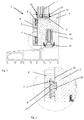
- FIG. 1 shows a first embodiment of the frame according to the invention, wherein only the lower leg of a movable wooden lifting sliding door element is shown in section.
- the in FIG. 1 shown frame 1 comprises an inner shell 2, which has a gradation 3 for receiving a glass element 4.
- the outer shell 5 consists of a wood material, in particular of wood.
- the outer shell 5 has T-shaped recesses in which reinforcements formed by aluminum profiles 7 are accommodated, which take over the function of connector elements of a first type.
- the aluminum profiles can extend over the entire length of an outer shell element, but this need not necessarily.
- several aluminum profiles may be provided per outer shell element.
- the aluminum profiles can be inserted in an advantageous manner in the longitudinal direction of the outer shell elements in the T-shaped recesses so that the illustrated positive connection results.
- the connector elements of the first type cooperate with connector elements of a second type 8 in order to connect the inner shell 2 with the outer shell 5 such that the glass element 4 is held between these shells 2,5.
- Both plug-in connection elements of the second type 8 can be, for example, plastic clips, in particular plastic clips of which in each case several are fastened at a distance from one another on the inner shell, for example by screw connections.
- a first sealing element 10 is provided, which may consist of a viscous material.
- a second sealing element 9 is provided, which simultaneously performs the function of a spacer element, so that the glass element 4 does not bear directly against the inner shell 2.
- the inner side 11 of the inner shell 2 is approximately flush with the right side wall of a threshold profile 21, which may be made of GRP or aluminum or combinations thereof, for example.
- a threshold profile 21 which may be made of GRP or aluminum or combinations thereof, for example.
- the in FIG. 1 only partially and in section shown lower leg of a movable wooden lifting sliding door element comprises at least two guide rollers, of which only one guide roller 24 is shown. This runs when moving the door element on the threshold profile 21 associated rail.
- FIG. 2 shows a detail FIG. 1 in an enlarged view. Shown in particular is the interaction between a plug connection element of the first type formed by the reinforcement 7 and a plug connection element of the second type 8.
- the reinforcement 7 is keyed in a recess of the outer shell 5, ie is in firm connection with the outer shell 5.
- the connector element of the second type 8 is attached to the inner shell 2, for example by a screw, not shown.
- the representation of FIG. 2 it can be seen, the outer shell 5 has been connected to the inner shell 2, in which the reinforcement 7 was hooked by a movement from top to bottom in the connector element of the second type 8.
- an optional the plug-in connection element of the second type 8 associated latching pin 26 is engaged in a recess 27 which is provided in the connector element of the first type 7.
- the skilled artisan will appreciate that can be determined by the shape of the locking pin 26 and the recess 26, whether, and if so, with what force, the connector by a movement of the outer shell 5 from bottom to top can be solved without destroying, for example, after To be able to use a new glass element 4 a glass breakage.
- engaging in a blind hole locking cylinder can not be brought into disambiguation virtually no longer, while such a take much more likely, for example, in a hemispherical locking pin and a half-shell-shaped recess.
- FIG. 3 shows a second embodiment of the frame according to the invention, wherein only the lower leg of a fixed wooden lifting sliding door element is shown in section. This may in particular to the wooden lifting sliding door of FIG. 1 belonging solid door element act.
- the entire frame is again denoted by 1.
- the inner shell 2 is formed in this embodiment by the threshold 20 with the threshold profile 21, a threshold insert 22 and a guide rail 23, said inner shell 2 again has a gradation 3 for receiving the glass element.
- both the reinforcement 7 and the second plug connection elements 8 are designed somewhat differently in this embodiment in order to prevent the lower outer shell element from extending downwards over the threshold profile 21.
- the connector element of the second type 8 is smaller than in the other cases.
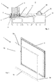
- FIG. 4 shows the inner and outer shell of the frame of FIG. 1 before their connection. Also in this illustration, the entire frame is provided with the reference numeral 1.
- the inner shell bears the reference numeral 2
- the outer shell is composed in this case of four outer shell elements 5a, 5b, 5c and 5d. If the outer shell elements 5a, 5b, 5c and 5d are already connected to each other before the outer shell is connected to the inner shell 2, all connections must be made simultaneously, for example by a movement of the outer shell from top to bottom, so that all the connector elements are aligned accordingly have to.
- the left outer shell member 5b may be fixed to the inner shell 2 by moving from right to left, followed by fixing the right outer shell member 5d by moving from left to right.
- the upper outer shell member 5a can be fixed by a movement from bottom to top, to finally the lower outer shell member 5c by a movement from top to bottom to lock. This can be done particularly easily if the outer shell elements 5 a, 5 b, 5 c and 5 d by the in FIG. 4 not shown glass element are performed.
- FIG. 5 shows a third embodiment of the frame according to the invention, wherein only the lower leg of a movable wooden lift-and-slide door element is shown in section.
- the representation of FIG. 5 corresponds to the representation of FIG. 1 , with the sole difference that the illustrated lower leg of the outer shell 5 is divided horizontally, so that initially only the lower part of this leg is fixed to the inner shell 2, wherein the upper part of this leg is subsequently mounted. The upper part engages behind the lower part while sections, as shown, to make a secure connection.
- FIG. 6 shows a first example of the use of first and second sealing means. It can be seen that the second sealing or spacer element 13 is elastically spread in a groove provided in the inner shell 2. That is, second seal member 13 is fixed to the inner shell 2 before the glass member 4 is inserted. Although not shown, the glass element 4 in this as well as in all other embodiments can be clogged in a conventional manner.
- the first sealing element 10 provided between the outer shell 5 and the glass element 4 may be, for example, a silicone sealing element. It may also be a hard stop the outer shell 5 may be provided.
- FIG. 7 shows a second example of the use of first and second sealing means.
- the representation of FIG. 7 only differs from the representation of FIG. 6 in that the first sealing element 10 and the second sealing element 13 are designed the same in this case, but the outer shell 5 is held by the plug connection elements 7, 8 at a distance from the glass element 4, while the glass element 4 rests in the inner shell 2.
- FIG. 3 Reference is made to illustrate one possible embodiment of the method according to the invention.
- the procedure is as follows. First, the existing from the elements 20 to 23 inner shell 2 is fixed to a building, for example, in a designated and appropriately sized recess. Subsequently, the glass element is inserted into the inner shell 2. Finally, the inner shell 2 with the Outer shell 5 is connected by plug-in connections, wherein the production of the connectors 7, 8 via reinforcements 7 of the outer shell 5 takes place.
Landscapes
- Engineering & Computer Science (AREA)
- Life Sciences & Earth Sciences (AREA)
- Wood Science & Technology (AREA)
- Civil Engineering (AREA)
- Structural Engineering (AREA)
- Securing Of Glass Panes Or The Like (AREA)
- Wing Frames And Configurations (AREA)
Applications Claiming Priority (1)
| Application Number | Priority Date | Filing Date | Title |
|---|---|---|---|
| DE102015007386.9A DE102015007386A1 (de) | 2015-06-10 | 2015-06-10 | Rahmen für ein Fenster- oder Schiebetürelement |
Publications (1)
| Publication Number | Publication Date |
|---|---|
| EP3103952A1 true EP3103952A1 (fr) | 2016-12-14 |
Family
ID=56092813
Family Applications (1)
| Application Number | Title | Priority Date | Filing Date |
|---|---|---|---|
| EP16171998.4A Withdrawn EP3103952A1 (fr) | 2015-06-10 | 2016-05-30 | Encadrement d'un element de porte coulissante ou de fenetre |
Country Status (2)
| Country | Link |
|---|---|
| EP (1) | EP3103952A1 (fr) |
| DE (1) | DE102015007386A1 (fr) |
Cited By (1)
| Publication number | Priority date | Publication date | Assignee | Title |
|---|---|---|---|---|
| DE202020107359U1 (de) | 2020-12-17 | 2022-03-18 | Holzbau Schmid GmbH u. Co. Kommanditgesellschaft | Festverglasung für ein Gebäude |
Families Citing this family (3)
| Publication number | Priority date | Publication date | Assignee | Title |
|---|---|---|---|---|
| EP3527768A1 (fr) * | 2018-02-20 | 2019-08-21 | MACO Technologie GmbH | Agencement pour un élément pivotant-coulissant |
| DE102018103776A1 (de) * | 2018-02-20 | 2019-08-22 | Maco Technologie Gmbh | Hebeschiebe-Element |
| DE102018007189A1 (de) * | 2018-02-20 | 2019-08-22 | Maco Technologie Gmbh | Anordnung für ein Hebeschiebe-Element |
Citations (4)
| Publication number | Priority date | Publication date | Assignee | Title |
|---|---|---|---|---|
| ITRG950001A1 (it) * | 1995-01-02 | 1996-07-02 | Giuseppe Bracchitta | Complesso di profilati per serramenti ottenuti collegando due elementi di diverso materiale con relativo metodo e dispositivo per la loro |
| EP0563030B1 (fr) | 1992-03-23 | 1998-07-08 | Internorm Fenster Aktiengesellschaft | Procédure et profil en plastique pour vitrage de fenêtre en matières synthétiques |
| EP1561892A2 (fr) * | 2004-02-06 | 2005-08-10 | Eichinger Schreinerei GmbH | Système de revêtement pour surfaces extérieures ou intérieures de bâtiments, portes, fenêtres et similaires |
| EP2690244A1 (fr) * | 2012-07-25 | 2014-01-29 | Christian Rupprecht | Elément de fenêtre ou de porte doté d'une sécurité supplémentaire contre l'effraction avec violence |
Family Cites Families (5)
| Publication number | Priority date | Publication date | Assignee | Title |
|---|---|---|---|---|
| FR2734310B1 (fr) * | 1995-05-19 | 2000-09-22 | Pab | Perfectionnement aux menuiseries en matiere plastique |
| DE29813338U1 (de) * | 1998-07-27 | 1998-11-12 | Spadinger, Bernd, 78183 Hüfingen | Holzfenster bzw. Holztür |
| PT102640B (pt) * | 2001-06-25 | 2007-04-30 | Anodil Extrusao E Distribuic D | Sistema de caixilharia em alumínio com revestimento interior em madeira |
| DE10344946A1 (de) * | 2003-09-27 | 2005-04-28 | Franz Karl Fa | Fenster oder Tür |
| ITFI20040198A1 (it) * | 2004-09-24 | 2004-12-24 | Giampiero Fabbri | Accoppiamento per profilati compositi di serramenti |
-
2015
- 2015-06-10 DE DE102015007386.9A patent/DE102015007386A1/de not_active Withdrawn
-
2016
- 2016-05-30 EP EP16171998.4A patent/EP3103952A1/fr not_active Withdrawn
Patent Citations (4)
| Publication number | Priority date | Publication date | Assignee | Title |
|---|---|---|---|---|
| EP0563030B1 (fr) | 1992-03-23 | 1998-07-08 | Internorm Fenster Aktiengesellschaft | Procédure et profil en plastique pour vitrage de fenêtre en matières synthétiques |
| ITRG950001A1 (it) * | 1995-01-02 | 1996-07-02 | Giuseppe Bracchitta | Complesso di profilati per serramenti ottenuti collegando due elementi di diverso materiale con relativo metodo e dispositivo per la loro |
| EP1561892A2 (fr) * | 2004-02-06 | 2005-08-10 | Eichinger Schreinerei GmbH | Système de revêtement pour surfaces extérieures ou intérieures de bâtiments, portes, fenêtres et similaires |
| EP2690244A1 (fr) * | 2012-07-25 | 2014-01-29 | Christian Rupprecht | Elément de fenêtre ou de porte doté d'une sécurité supplémentaire contre l'effraction avec violence |
Cited By (1)
| Publication number | Priority date | Publication date | Assignee | Title |
|---|---|---|---|---|
| DE202020107359U1 (de) | 2020-12-17 | 2022-03-18 | Holzbau Schmid GmbH u. Co. Kommanditgesellschaft | Festverglasung für ein Gebäude |
Also Published As
| Publication number | Publication date |
|---|---|
| DE102015007386A1 (de) | 2016-12-15 |
Similar Documents
| Publication | Publication Date | Title |
|---|---|---|
| EP3401495B2 (fr) | Construction de façade/fenêtre et installation de protection solaire correspondante | |
| CH699782A2 (de) | Rahmenanschlussteil zur Befestigung an einem Rahmen. | |
| WO2016131909A1 (fr) | Dispositif d'étanchéité pour éléments de fenêtre et éléments de porte | |
| EP0202510B1 (fr) | Chambranle ou cadre de battant pour fenêtres ou portes | |
| DE102015007386A1 (de) | Rahmen für ein Fenster- oder Schiebetürelement | |
| AT516308B1 (de) | Fensterelement | |
| EP1978171B1 (fr) | Façade avec montants et traverses en construction modulaire | |
| EP2796652B1 (fr) | Dormant de porte | |
| EP0690951A1 (fr) | Profile mixte bois-aluminium | |
| EP1643049B1 (fr) | Construction avec profilés porteurs | |
| DE102004014515A1 (de) | Stoßverbinder zum winkeligen Verbinden von Hohlprofilen | |
| EP3293336B1 (fr) | Rail de retenue pour un balcon français ainsi que dispositif et système de retenue associés | |
| CH702394B1 (de) | Schiebewand mit wenigstens zwei Flügeln. | |
| DE102007006824B4 (de) | Multifunktionsblendrahmen | |
| EP2292885B1 (fr) | Système de fenêtre préfabriquée et d'éléments muraux préfabriqués analogues | |
| AT406785B (de) | Verkleidungselemente | |
| DE102013013074B4 (de) | Zargenkonstruktion zum Anschluss eines Fenster- oder Türrahmens an eine Gebäudewand | |
| DE102011001726B4 (de) | Modul zur Aufnahme einer Schiebetür, Schiebetürvorrichtung und Verfahren zur Montage einer Schiebetürvorrichtung | |
| DE20100618U1 (de) | Rahmenprofil | |
| DE102012104000B4 (de) | Halter zur Fixierung eines Isolationskörpers an einer Pfosten- und Riegelanordnung und eine solche Pfosten- und Riegelanordnung | |
| DE102007005290B4 (de) | Revisionsvorrichtung | |
| EP4012147A1 (fr) | Insert de feuillure de verre pour un profilé de cadre de fenêtre et système et procédé de vitrage d'un cadre de fenêtre | |
| EP2639396B1 (fr) | Pièce d'étanchéité et agencement de cadre | |
| DE102024125127A1 (de) | Haltevorrichtung für ein flächenelement | |
| DE102004051617B3 (de) | Verglasungselement |
Legal Events
| Date | Code | Title | Description |
|---|---|---|---|
| PUAI | Public reference made under article 153(3) epc to a published international application that has entered the european phase |
Free format text: ORIGINAL CODE: 0009012 |
|
| AK | Designated contracting states |
Kind code of ref document: A1 Designated state(s): AL AT BE BG CH CY CZ DE DK EE ES FI FR GB GR HR HU IE IS IT LI LT LU LV MC MK MT NL NO PL PT RO RS SE SI SK SM TR |
|
| AX | Request for extension of the european patent |
Extension state: BA ME |
|
| STAA | Information on the status of an ep patent application or granted ep patent |
Free format text: STATUS: THE APPLICATION IS DEEMED TO BE WITHDRAWN |
|
| 18D | Application deemed to be withdrawn |
Effective date: 20170615 |