EP3104005A1 - Système de diagnostic pour machine hydraulique, une machine hydraulique, une appareil de génération d'énergie éolienne et une procédé de diagnostic de machine hydraulique - Google Patents
Système de diagnostic pour machine hydraulique, une machine hydraulique, une appareil de génération d'énergie éolienne et une procédé de diagnostic de machine hydraulique Download PDFInfo
- Publication number
- EP3104005A1 EP3104005A1 EP16154339.2A EP16154339A EP3104005A1 EP 3104005 A1 EP3104005 A1 EP 3104005A1 EP 16154339 A EP16154339 A EP 16154339A EP 3104005 A1 EP3104005 A1 EP 3104005A1
- Authority
- EP
- European Patent Office
- Prior art keywords
- pressure
- valve
- hydraulic machine
- pressure valve
- low
- Prior art date
- Legal status (The legal status is an assumption and is not a legal conclusion. Google has not performed a legal analysis and makes no representation as to the accuracy of the status listed.)
- Granted
Links
Images


Classifications
-
- F—MECHANICAL ENGINEERING; LIGHTING; HEATING; WEAPONS; BLASTING
- F04—POSITIVE - DISPLACEMENT MACHINES FOR LIQUIDS; PUMPS FOR LIQUIDS OR ELASTIC FLUIDS
- F04B—POSITIVE-DISPLACEMENT MACHINES FOR LIQUIDS; PUMPS
- F04B17/00—Pumps characterised by combination with, or adaptation to, specific driving engines or motors
- F04B17/02—Pumps characterised by combination with, or adaptation to, specific driving engines or motors driven by wind motors
-
- F—MECHANICAL ENGINEERING; LIGHTING; HEATING; WEAPONS; BLASTING
- F03—MACHINES OR ENGINES FOR LIQUIDS; WIND, SPRING, OR WEIGHT MOTORS; PRODUCING MECHANICAL POWER OR A REACTIVE PROPULSIVE THRUST, NOT OTHERWISE PROVIDED FOR
- F03C—POSITIVE-DISPLACEMENT ENGINES DRIVEN BY LIQUIDS
- F03C1/00—Reciprocating-piston liquid engines
- F03C1/02—Reciprocating-piston liquid engines with multiple-cylinders, characterised by the number or arrangement of cylinders
- F03C1/04—Reciprocating-piston liquid engines with multiple-cylinders, characterised by the number or arrangement of cylinders with cylinders in star or fan arrangement
- F03C1/0403—Details, component parts specially adapted of such engines
- F03C1/0406—Pistons
-
- F—MECHANICAL ENGINEERING; LIGHTING; HEATING; WEAPONS; BLASTING
- F03—MACHINES OR ENGINES FOR LIQUIDS; WIND, SPRING, OR WEIGHT MOTORS; PRODUCING MECHANICAL POWER OR A REACTIVE PROPULSIVE THRUST, NOT OTHERWISE PROVIDED FOR
- F03D—WIND MOTORS
- F03D17/00—Monitoring or testing of wind motors, e.g. diagnostics
-
- F—MECHANICAL ENGINEERING; LIGHTING; HEATING; WEAPONS; BLASTING
- F03—MACHINES OR ENGINES FOR LIQUIDS; WIND, SPRING, OR WEIGHT MOTORS; PRODUCING MECHANICAL POWER OR A REACTIVE PROPULSIVE THRUST, NOT OTHERWISE PROVIDED FOR
- F03D—WIND MOTORS
- F03D9/00—Adaptations of wind motors for special use; Combinations of wind motors with apparatus driven thereby; Wind motors specially adapted for installation in particular locations
- F03D9/20—Wind motors characterised by the driven apparatus
- F03D9/28—Wind motors characterised by the driven apparatus the apparatus being a pump or a compressor
-
- F—MECHANICAL ENGINEERING; LIGHTING; HEATING; WEAPONS; BLASTING
- F04—POSITIVE - DISPLACEMENT MACHINES FOR LIQUIDS; PUMPS FOR LIQUIDS OR ELASTIC FLUIDS
- F04B—POSITIVE-DISPLACEMENT MACHINES FOR LIQUIDS; PUMPS
- F04B1/00—Multi-cylinder machines or pumps characterised by number or arrangement of cylinders
- F04B1/04—Multi-cylinder machines or pumps characterised by number or arrangement of cylinders having cylinders in star- or fan-arrangement
- F04B1/0404—Details or component parts
- F04B1/0408—Pistons
-
- F—MECHANICAL ENGINEERING; LIGHTING; HEATING; WEAPONS; BLASTING
- F04—POSITIVE - DISPLACEMENT MACHINES FOR LIQUIDS; PUMPS FOR LIQUIDS OR ELASTIC FLUIDS
- F04B—POSITIVE-DISPLACEMENT MACHINES FOR LIQUIDS; PUMPS
- F04B49/00—Control, e.g. of pump delivery, or pump pressure of, or safety measures for, machines, pumps, or pumping installations, not otherwise provided for, or of interest apart from, groups F04B1/00 - F04B47/00
- F04B49/22—Control, e.g. of pump delivery, or pump pressure of, or safety measures for, machines, pumps, or pumping installations, not otherwise provided for, or of interest apart from, groups F04B1/00 - F04B47/00 by means of valves
-
- F—MECHANICAL ENGINEERING; LIGHTING; HEATING; WEAPONS; BLASTING
- F04—POSITIVE - DISPLACEMENT MACHINES FOR LIQUIDS; PUMPS FOR LIQUIDS OR ELASTIC FLUIDS
- F04B—POSITIVE-DISPLACEMENT MACHINES FOR LIQUIDS; PUMPS
- F04B51/00—Testing machines, pumps, or pumping installations
-
- F—MECHANICAL ENGINEERING; LIGHTING; HEATING; WEAPONS; BLASTING
- F04—POSITIVE - DISPLACEMENT MACHINES FOR LIQUIDS; PUMPS FOR LIQUIDS OR ELASTIC FLUIDS
- F04B—POSITIVE-DISPLACEMENT MACHINES FOR LIQUIDS; PUMPS
- F04B53/00—Component parts, details or accessories not provided for in, or of interest apart from, groups F04B1/00 - F04B23/00 or F04B39/00 - F04B47/00
- F04B53/10—Valves; Arrangement of valves
-
- F—MECHANICAL ENGINEERING; LIGHTING; HEATING; WEAPONS; BLASTING
- F05—INDEXING SCHEMES RELATING TO ENGINES OR PUMPS IN VARIOUS SUBCLASSES OF CLASSES F01-F04
- F05B—INDEXING SCHEME RELATING TO WIND, SPRING, WEIGHT, INERTIA OR LIKE MOTORS, TO MACHINES OR ENGINES FOR LIQUIDS COVERED BY SUBCLASSES F03B, F03D AND F03G
- F05B2260/00—Function
- F05B2260/40—Transmission of power
- F05B2260/406—Transmission of power through hydraulic systems
-
- Y—GENERAL TAGGING OF NEW TECHNOLOGICAL DEVELOPMENTS; GENERAL TAGGING OF CROSS-SECTIONAL TECHNOLOGIES SPANNING OVER SEVERAL SECTIONS OF THE IPC; TECHNICAL SUBJECTS COVERED BY FORMER USPC CROSS-REFERENCE ART COLLECTIONS [XRACs] AND DIGESTS
- Y02—TECHNOLOGIES OR APPLICATIONS FOR MITIGATION OR ADAPTATION AGAINST CLIMATE CHANGE
- Y02E—REDUCTION OF GREENHOUSE GAS [GHG] EMISSIONS, RELATED TO ENERGY GENERATION, TRANSMISSION OR DISTRIBUTION
- Y02E10/00—Energy generation through renewable energy sources
- Y02E10/70—Wind energy
- Y02E10/72—Wind turbines with rotation axis in wind direction
-
- Y—GENERAL TAGGING OF NEW TECHNOLOGICAL DEVELOPMENTS; GENERAL TAGGING OF CROSS-SECTIONAL TECHNOLOGIES SPANNING OVER SEVERAL SECTIONS OF THE IPC; TECHNICAL SUBJECTS COVERED BY FORMER USPC CROSS-REFERENCE ART COLLECTIONS [XRACs] AND DIGESTS
- Y02—TECHNOLOGIES OR APPLICATIONS FOR MITIGATION OR ADAPTATION AGAINST CLIMATE CHANGE
- Y02P—CLIMATE CHANGE MITIGATION TECHNOLOGIES IN THE PRODUCTION OR PROCESSING OF GOODS
- Y02P80/00—Climate change mitigation technologies for sector-wide applications
- Y02P80/10—Efficient use of energy, e.g. using compressed air or pressurized fluid as energy carrier
Definitions
- the present disclosure relates to a diagnosis system for a hydraulic machine, a hydraulic machine, a wind turbine power generating apparatus, and a method of diagnosing a hydraulic machine.
- Patent Document 1 describes a hydraulic machine which performs conversion between fluid energy of working fluid and rotational energy of a rotation shaft, utilizing a cyclic volume change of a working chamber formed by a cylinder and a piston.
- Patent Document 2 describes an approach for suppressing occurrence of abnormality in opening and closing of a valve for switching a communication state between a working chamber of a hydraulic machine and outside of the working chamber, which is to control an opening-closing timing of the valve in accordance with the characteristics of the constituent members of a fluid working machine or a state of working fluid (working oil).
- an object of at least one embodiment of the present invention is to provide a diagnosis system for a hydraulic machine, a hydraulic machine, a wind turbine power generating apparatus, and a method of diagnosing a hydraulic machine whereby it is possible to diagnose abnormality of the hydraulic machine precisely.
- a pressure in a working chamber changes in accordance with opening and closing of the high-pressure valve and the low-pressure valve, and with the reciprocating motion of the piston.
- a chamber pressure fluctuates cyclically during normal operation of a hydraulic machine.
- the cyclic change of the chamber pressure is achieved by controlling the high-pressure valve or the low-pressure valve.
- the high-pressure valve or the low-pressure valve is a valve in which the position of a valve body is controlled to switch between a normal position (open position or closed position) and an excitation position by supply control of excitation current
- the chamber pressure fluctuates cyclically by controlling the supply of the excitation current to open or close the valve so that the hydraulic machine performs required motion.
- the valve body when the high-pressure valve or the low-pressure valve is not supplied with the excitation current, the valve body is normally at the normal position due to a biasing force applied to the valve body. However, if a force in a direction opposite to that of the biasing force acts on the valve body due to some reason, a phenomenon such that valve body gets fixed to the excitation position even when not supplied with the excitation current may occur. If the motion of the valve is different from desired motion, the pressure in the working chamber changes in a manner different from the above described cyclic pressure fluctuation.
- a diagnosis system for a hydraulic machine, a hydraulic machine, a wind turbine power generating apparatus, and a method of diagnosing a hydraulic machine whereby it is possible to diagnose abnormality of the hydraulic machine precisely are provided.
- a hydraulic machine according to one embodiment of the present invention will be described, referring to a hydraulic motor of a hydraulic transmission constituting a drive train of a wind turbine power generating apparatus as an example.
- a hydraulic machine is not limited to the example herein, and may be a hydraulic pump or a hydraulic motor to be applied to a certain usage.
- the wind turbine power generating apparatus includes a hydraulic machine (hydraulic motor) to which the diagnosis system and method according to one embodiment are to be applied.
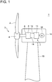
- FIG. 1 is a schematic diagram of a wind turbine power generating apparatus according to one embodiment. As illustrated in the drawing, the wind turbine power generating apparatus 1 includes a rotor 3 configured to rotate by receiving wind, a hydraulic transmission 7 for transmitting rotation of the rotor 3, a generator 16 for generating electric power.
- the rotor 3 includes at least one blade 2, and a hub 4 to which the at least one blade 2 is mounted.
- the hydraulic transmission 7 includes a hydraulic pump 8 connected to the rotor 3 via a rotation shaft 6, a hydraulic motor 10, and a high-pressure line 12 and a low-pressure line 14 connecting the hydraulic pump 8 and the hydraulic motor 10.
- the generator 16 is coupled to the hydraulic motor 10 via an output shaft of the hydraulic motor 10.
- the generator 16 is a synchronous generator connected to a utility grid and driven by the hydraulic motor 10.
- the hydraulic pump 8, the hydraulic motor 10, and the generator 16 may be disposed inside a nacelle 18 disposed on a tower 19.
- the rotation energy of the rotor 3 is inputted into the generator 16 via the hydraulic transmission 7 including the hydraulic pump 8 and the hydraulic motor 10, and electric power is generated by the generator 16.
- the entire rotor 3 rotates by the power of the wind, so that the hydraulic pump 8 is driven by the rotor 3 to pressurize working oil, thereby producing high-pressure working oil (pressurized oil).
- the pressurized oil produced by the hydraulic pump 8 is supplied to the hydraulic motor 10 via the high-pressure line 12, and drives the hydraulic motor 10.
- Electric power is generated by the generator 16 connected to the hydraulic motor 10 via the output shaft.
- the low-pressure working oil having performed work in the hydraulic motor 10 flows again into the hydraulic pump 8 via the low-pressure line 14.
- the hydraulic pump 8 and the hydraulic motor 10 may be of variable-displacement type whereby the displacement is adjustable.
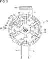
- FIGs. 2 and 3 are each a schematic diagram of a diagnosis system for a hydraulic motor (hydraulic machine) according to one embodiment.
- the hydraulic motor 10 to be diagnosed by the diagnosis system and method includes a rotation shaft 32, a cylinder 20, a piston 22 which forms a working chamber 24 with the cylinder 20, and a high-pressure valve 28 and a low-pressure valve 30 provided for the working chamber 24, and a cam 26 (conversion mechanism) for performing conversion between the reciprocating motion of the piston 22 and the rotational motion of the rotation shaft 32.
- the cam 26 has a cam curved surface configured to contact the piston 22.
- the piston 22 preferably includes a piston body portion 22A which slides inside the cylinder 20, and a piston roller or a piston shoe which is attached to the piston body portion 22A and which contacts the cam curved surface of the cam 26, from the perspective of smoothly converting the reciprocating motion of the piston 22 into the rotational motion of the rotation shaft 32.
- the piston 22 includes a piston body portion 22A and a piston shoe 22B.
- the cam 26 is an eccentric cam disposed eccentrically from the axial center O of the rotation shaft (crank shaft) 32 of the hydraulic motor 10. While the piston 22 performs a set of upward and downward movement, the cam 26 and the rotation shaft 32 to which the cam 26 is mounted perform one revolution.
- the cam 26 is an annular-shaped multi-lobed cam (ring cam) with a plurality of lobes. In this case, while the cam 26 and the rotation shaft 32 to which the cam 26 is mounted perform one revolution, the piston 22 performs as many sets of upward and downward movement as the number of lobes.
- the high-pressure valve 28 is disposed in a high-pressure communication line 34 between the working chamber 24 and the high-pressure line 12 disposed outside the working chamber 24, and configured to be capable of switching the communication state between the working chamber 24 and the high-pressure line 12.
- the low-pressure valve 30 is disposed in a low-pressure communication line 36 between the working chamber 24 and the low-pressure line 14 disposed outside the working chamber 24, and configured to be capable of switching the communication state between the working chamber 24 and the low-pressure line 14.
- a diagnosis system 70 of the hydraulic motor 10 illustrated in FIGs. 2 and 3 includes a monitor/controller 110 for controlling and monitoring the operation state of a device (e.g. the high-pressure valve 28 and the low-pressure valve 30) constituting the hydraulic motor 10, or an instrument (e.g. the pressure sensor 72 described below).
- the monitor/controller 110 includes an abnormality determination part 118 for determining abnormality of the hydraulic motor 10 (hydraulic machine) and a controller 111 for controlling a device constituting the hydraulic motor 10.
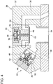
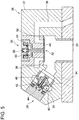
- FIGs. 4 and 5 are each a schematic cross-sectional view of the configuration of the high-pressure valve 28 and the low-pressure valve 30.
- FIG. 4 illustrates a situation where the high-pressure valve 28 is closed and the low-pressure valve 30 is open
- FIG. 5 illustrates a situation where the high-pressure valve 28 is open and the low-pressure valve 30 is closed.
- the high-pressure valve 28, the low-pressure valve 30, and a casing 37 of the valves may be unitized and configured as a valve unit 38, as illustrated in FIGs. 4 and 5 .
- the high-pressure valve 28 and the low-pressure valve 30 are controlled to open and close by a valve control part 112 (see FIG. 3 ) that the controller 111 includes.
- the valve control part 112 controls the opening-closing motion of the high-pressure valve 28 by applying a HPV control signal (opening-closing command for the high-pressure valve 28) to the high-pressure valve 28, and controls the opening-closing motion of the low-pressure valve 30 by applying a LPV control signal (opening-closing command for the low-pressure valve 30) to the low-pressure valve 30.
- the high-pressure valve 28 illustrated in FIGs. 4 and 5 includes a movable unit 40 including a valve body 35, a solenoid coil 42 that functions as an actuator for moving the movable unit 40 between a valve-open position and a valve-closed position, a spring 44, and a valve seat 46.
- the high-pressure valve 28 is a poppet solenoid valve of normally-closed type, with the valve seat 46 disposed on a side adjacent to the working chamber 24 with respect to the valve body 35.
- the high-pressure valve 28 is capable of switching the communication state between the working chamber 24 and the high-pressure line 12 (see FIG. 12) by movement of the movable unit 40 caused by the electromagnetic force of the solenoid coil 42 or the biasing force of the spring 44.
- the movable unit 40 When the high-pressure valve 28 is not excited by the HPV control signal from the valve control part 112, the movable unit 40 is biased toward the valve seat 46 by the spring 44, so as to be retained in a position such that the working chamber 24 and the high-pressure line 12 are not in communication (normal position; the position of the movable unit 40 in FIG. 4 ).
- the movable unit 40 moves to a position such that the working chamber 24 and the high-pressure line 12 communicate with each other by the electromagnetic force, against the biasing force of the spring 44 (excitation position; the position of the movable unit 40 in FIG. 5 ).
- the high-pressure valve 28 is configured such that the valve body is movable by the supply control of the excitation current, between the normal position where the excitation current is not supplied and the excitation position where the excitation current is supplied.
- the low-pressure valve 30 illustrated in FIGs. 4 and 5 includes a movable unit 52 including a valve body 48 and an armature 50, a solenoid coil 54, a spring 56, and a valve seat 58.
- the low-pressure valve 30 is a poppet solenoid valve of normally-open type, with the valve body 48 disposed on the side of the working chamber 24 with respect to the valve seat 58.
- the low-pressure valve 30 is capable of switching the communication state between the working chamber 24 and the low-pressure line 14 (see FIG. 2 ) by movement of the movable unit 52 caused by the electromagnetic force of the solenoid coil 54 or the biasing force of the spring 56.
- the movable unit 52 When the low-pressure valve 30 is not excited by the LPV control signal from the valve control part 112, the movable unit 52 is biased in a direction away from the valve seat 58 by the spring 56, so as to be retained in a valve-open position such that the working chamber 24 and the low-pressure line 14 are in communication with each other (normal position; the position of the movable unit 52 in FIG. 4 ).
- the low-pressure valve 30 When the low-pressure valve 30 is excited by the LPV control signal from the valve control part 112, the electromagnetic force of the solenoid coil 54 attracts the armature 50 and the movable unit 52 moves toward the valve seat 58 by the electromagnetic force against the biasing force of the spring 56, thereby moving to a valve-closed position such that the working chamber 24 and the high-pressure line 12 are not in communication (excitation position; the position of the movable unit 52 in FIG. 5 ).
- the low-pressure valve 30 is configured such that the valve body is movable by the supply control of the excitation current, between the normal position where the excitation current is not supplied and the excitation position where the excitation current is supplied.
- the diagnosis system 70 of the hydraulic motor 10 includes a pressure sensor 72 for measuring a pressure of the working chamber 24.
- the signal representing the pressure of the working chamber 24 measured by the pressure sensor 72 is inputted to the monitor/controller 110.
- the measurement result obtained by the pressure sensor 72 is used by the abnormality determination part 118 to determine abnormality of the hydraulic motor 10.
- the abnormality determination part 118 includes the first abnormality determination part 114 and/or the second abnormality determination part described below.
- a signal representing an electric-current value measured by an electric-current measuring part 74 for measuring a value of the excitation current supplied to the low-pressure valve 30 is inputted to the monitor/controller 110.
- each of the working chambers 24 may include the pressure sensor 72, as illustrated in FIG. 2 .
- the diagnosis system 70 of the hydraulic motor 10 includes the first abnormality determination part 114 for determining abnormality of the hydraulic machine on the basis of the measurement result of the pressure sensor 72.
- the first abnormality determination part 114 determines abnormality of the hydraulic motor 10 on the basis of the measurement result obtained by the pressure sensor 72 when the low-pressure valve 30 is not supplied with the excitation current.
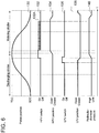
- FIG. 6 is a diagram illustrating the opening-closing motion of the high-pressure valve 28 and the low-pressure valve 30 and a pressure fluctuation inside the working chamber 24 while the cylinder 20 performs an active cycle.
- An active cycle of the hydraulic motor 10 refers to a cycle in which pressurized oil from the hydraulic pump 8 performs a work to rotate the rotation shaft of the hydraulic motor 10 in the cylinder 20, i.e., a cycle in which the displacement of the working oil is generated.
- the piston-cycle curve 130 is a curve representing a time-series change of the position of a piston 22, where the x-axis is time t.
- an HPV control signal 132 represents a control signal to be supplied to the high-pressure valve 28
- a high-pressure valve position 134 represents an open/closed state of the high-pressure valve 28
- an LPV control signal 136 represents a control signal to be supplied to the low-pressure valve 30
- a low-pressure valve position 138 represents an open/closed state of the low-pressure valve 30
- a pressure curve 140 represents a pressure in the working chamber 24.
- the differential pressure between the high-pressure line 12 and the low-pressure line 14 created by the hydraulic pump 8 moves the pistons 22 upward and downward cyclically, so that each piston 22 repeats a discharging stroke of moving toward a top dead center from a bottom dead center and a motoring stroke of moving toward a bottom dead center from a top dead center.
- the HPV control signal 132 is applied to the high-pressure valve 28 of normally-closed type. As represented by the HPV control signal 132 in FIG. 6 , the high-pressure valve 28 is supplied with the excitation current immediately before the piston 22 reaches the top dead center, and thereby the high-pressure valve opens as represented by the high-pressure valve position 134.
- the high-pressure valve 28 opens, the high-pressure fluid flows into the working chamber 24 to rotate the cam 26.
- a biasing force a force acting in a direction to close the high-pressure valve 28
- repeating excitation and de-excitation of the high-pressure valve 28 at a high frequency makes it possible to latch the high-pressure valve 28 in an open state using little current. For instance, a signal having a duty ratio of 20 % and a cycle of 10kHz can be used.
- the pulse control signal given to the high-pressure valve 28 preferably has a higher frequency than that of the reciprocal number of a time constant of the coil of the high-pressure valve 28, from the perspective of securely maintaining the high-pressure valve 28 to be open.
- the final pulse 132A of the high-frequency signal repeating excitation and de-excitation of the high-pressure valve 28 may be regarded as a control signal for switching the high-pressure valve 28 from an open state to a closed state.
- the low-pressure valve 30 of normally-open type the low-pressure valve 30 is excited (closed) immediately before the piston 22 reaches the top dead center, and then the high-pressure valve 28 is excited (opened), so that the low-pressure valve 30 is maintained to be closed by the differential pressure between the opposite sides of the valve body 48.
- the low-pressure valve 30 is closed by being excited immediately before the piston 22 reaches the top dead center.
- the low-pressure valve 30 is maintained to be closed by the differential pressure between the working chamber 24 and the low-pressure line 14 even if the low-pressure valve 30 is closed by excitation and then de-excited before the piston 22 reaches the top dead center, because the pressure in the working chamber 24 is high (see the pressure curve 140) during a period during which the piston 22 moves toward the top dead center (a period in the discharging stroke after the low-pressure valve 98 is closed).
- FIGs. 7A to 7D are each a schematic graph showing a change in the excitation current to the low-pressure valve 30 over time t, and a measurement result (i.e., a change in the pressure inside the working chamber 24, which is a chamber pressure) obtained by the pressure sensor 72 corresponding to the same.
- FIG. 7A illustrates a case in which the cylinder is performing an active cycle while the hydraulic motor 10 is in normal operation.
- FIG. 7B illustrates a case in which the cylinder is performing an inactive cycle while the hydraulic motor 10 is in normal operation. In both of FIGs.
- FIG. 7C illustrates a case in which the self-pumping described below is occurring
- FIG. 7D illustrates a case in which the juddering described below is occurring.
- "low-pressure valve(LPV) current” of y-axis represents the magnitude of the excitation current to the low-pressure valve 30.
- “ON” refers to the excitation current when the excitation current is supplied to the low-pressure valve 30, and “OFF” to that when the excitation current is not supplied.
- chamber pressure of y-axis represents the magnitude of the pressure inside the working chamber 24.
- T BDC1 , t BDC2 , and the like of x-axis represent the time points at which the piston 22 passes through the bottom dead center. Specifically, a period from t BDC1 to t BDC2 and a period from t BDC2 to t BDC3 correspond to a rotational cycle T* of the rotation shaft 32, which is a cycle of the reciprocating motion of the piston 22.
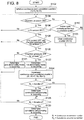
- FIG. 8 is a flowchart illustrating an example of a process for determining abnormality of the hydraulic motor 10 (hydraulic machine) by the first abnormality determination part 114 according to one embodiment.
- "chamber pressure ON” refers to when the chamber pressure is at least a threshold
- "chamber pressure OFF” to when the chamber pressure is less than the threshold
- "low-pressure valve (LPV) current OFF” to when the excitation current to the low-pressure valve 30 is at most a threshold.
- the high-pressure valve 28 and the low-pressure valve 30 are repetitively excited and de-excited in relation to the reciprocating cycle of the piston 22, so that the pressure inside the working chamber 24 changes cyclically.
- the cyclic change of the excitation current to the low-pressure valve 30 and the chamber pressure is, for instance, as illustrated in FIG. 7A .
- the high-pressure valve 28 and the low-pressure valve 30 are both in a de-excited state, in which the high-pressure valve 28 is constantly closed and the low-pressure valve 30 is constantly open, so that the working chamber 24 is in communication with the low-pressure line 14.
- the pressure inside the working chamber 24 is relatively low (which may be substantially the same as the pressure of the low-pressure line 14) throughout a cycle (the rotation cycle of the rotation shaft 32) of the cylinder 20.
- the change of the excitation current to the low-pressure valve 30 and the chamber pressure is, for instance, as illustrated in FIG. 7B .
- the excitation current to the low-pressure valve 30 is constantly OFF and the chamber pressure is also constantly OFF throughout the cycle of the cylinder 20.
- the low-pressure valve 30 may close unintentionally due to some reason even if the low-pressure valve 30 is de-excited, and the chamber pressure may increase as shown in the graph of FIG. 7C , which is a phenomenon called self pumping.
- self pumping occurs in the hydraulic motor 10
- the performance of the hydraulic motor 10 may decrease, or the low-pressure valve 30 may get damaged.
- the first abnormality determination part 114 measures a period t 1 during which the pressure of the working chamber 24 is at least the second threshold P th2 (see S104 in FIG. 8 ) in a period during which the excitation current to the low-pressure valve 30 is at most the first threshold I th1 (see S106 of FIG. 8 ) and the rotation shaft 32 performs one revolution (period T* in FIG. 7 ). Then, if the period t 1 continues for at least a predetermined period T 1 (Yes in S108 of FIG.
- the first threshold I th1 of the excitation current may be a mean value of the current value of when the excitation current is ON and the mean value of when the excitation current is OFF.
- the second threshold P th2 of the pressure of the working chamber 24 may be a mean value of the pressure of when the chamber pressure is ON and the pressure of when the chamber pressure is OFF.
- the length of the period t 1 during which the chamber pressure is at least the second threshold P th2 (the chamber pressure is ON) may be obtained on the basis of the increase time point and the decrease time point of the chamber pressure.
- the period t 1 may be from the increase-starting time point t up to the decrease-starting time point t down of the chamber pressure (see FIG. 7C ).
- the period t 1 may be from an increase-ending time point to a decrease-ending time point of the chamber pressure (not illustrated).
- the period from the increase time point to the decrease time point of the chamber pressure may be regarded to have the length of the period t 1 during which the chamber pressure is at least a threshold (chamber pressure is ON).
- a relative phase time axis
- a relative phase is used as a basis of a period during which the chamber pressure is ON during one revolution of the rotation shaft 32, instead of an absolute phase (rotational angle) of the rotation shaft. In this way, it is no longer necessary to take into account inconvenient matters such as an error like a phase error which may occur in a rotation-pulse sensor for measuring the rotation angle.
- the first abnormality determination part 114 after determining whether there is abnormality in the hydraulic motor 10 on the basis of the length t 1 of the period during which the chamber pressure is at least the second threshold P th2 (the chamber pressure is ON) as described above, the first abnormality determination part 114 measures a period t 2 during which the pressure inside the working chamber 24 is at most the third threshold P th3 (the chamber pressure is OFF) during one revolution of the rotation shaft 32 of the hydraulic motor 10. Then, on the basis of whether the above period t 2 continues for at least the predetermined period T 2 , the first abnormality determination part 114 determines the abnormality mode of the hydraulic machine (see S120 in FIG. 8 ).
- the first abnormality determination part 114 determines that the second abnormality mode (juddering; see FIG. 7D ) in which the low-pressure valve fails to open due to a delay in the closing timing of the high-pressure valve, if the period t 2 does not continue for at least the predetermined period T 2 . Further, the first abnormality determination part 114 determines that the first abnormality mode (the above described self pumping; see FIG. 7C ) in which the low-pressure valve opens as the high-pressure valve closes at an appropriate timing but the valve body of the low-pressure valve closes even when the low-pressure valve is not supplied with the excitation current, if the period t 2 continues for at least the predetermined period T 2 (see S120 of FIG. 8 ).
- Juddering is a phenomenon that occurs during an active cycle of the cylinder 20, in which the high-pressure valve 28 does not close normally in the vicinity of the bottom dead center of the piston 22 and thus the low-pressure valve 30 fails to open even though being de-excited, so that the pressure inside the working chamber 24 is high in most time of the rotational cycle of the rotation shaft 32.
- the juddering illustrated in FIG. 7D is intermittent juddering, in which the high-pressure valve 28 closes at a timing later than a predetermined timing, and thereby the piston 22 reaches the bottom dead center while the low-pressure valve 30 cannot open even when de-excited due to a fluid pressure differential applied to either side of the valve body 48.
- the period during which the chamber pressure is at least the second threshold P th2 (the chamber pressure is ON) is longer when the intermittent juddering is occurring than when the operation is normal as illustrated in FIG. 7A .
- juddering called “continuous juddering” may also occur, in which the valve body 35 becomes immovable due to sticking of the movable unit 40 of the high-pressure valve 28 or entry of foreign matters, so that the high-pressure valve 28 fails to close and continues to be open during the entire period of the reciprocating motion of the piston 22.
- the period during which the chamber pressure is at least the second threshold P th2 (the chamber pressure is ON) is remarkably longer when the continuous juddering is occurring than when the operation is normal as illustrated in FIG. 7A .
- the chamber pressure may decrease rapidly and then immediately increase, as indicated by arrow "A" in FIG. 7D .
- an event may occur, in which the period t 1 during which the pressure of the working chamber 24 is at least the second threshold P th2 continues for at least the predetermined period T 1 in a period (period T* in FIG. 7 ) during which the excitation current to the low-pressure valve 30 is at most the first threshold I th1 and the rotation shaft 32 performs one revolution.
- the period t 1 continues for at least the predetermined period T 1 , there is a risk of wrongly determining that the above described "self pumping" event is occurring.
- Self pumping and juddering are similar in that the low-pressure valve is kept closed unintentionally and the chamber pressure is high.
- the cause of the self-pumping is malfunction of the operation of the low-pressure valve
- the cause of the juddering is malfunction of the operation of the high-pressure valve. Since the two phenomena are caused by different mechanisms, it is desirable to be able to determine which phenomenon of self pumping (the first abnormality mode) or juddering (the second abnormality mode) is occurring, in order to determine abnormality of the hydraulic motor 10 appropriately.
- Self pumping occurs after occurrence of an event in which the high-pressure valve 28 closes just before the piston 22 moves to reach the bottom dead center from the top dead center so that the volume of the working chamber expands to decrease the chamber pressure and the low-pressure valve 30 is open.
- the chamber pressure is low (OFF) for a predetermined period in the reciprocating cycle of the piston 22. Therefore, on the basis of T 2 satisfying the above relationship, it is possible to determine whether the current abnormality event is self-pumping.
- abnormality self pumping
- the accuracy of the abnormality determination may be low.
- abnormality self pumping
- the first abnormality determination part 114 determines that abnormality is occurring in the hydraulic motor 10, if the continuous occurrence number N 1 of an event exceeds a threshold, the event being such that the period t 1 during which the pressure of the working chamber 24 is at least the second threshold P th2 continues for at least the predetermined period T 1 , in a period (period of length T*) during which the excitation current to the low-pressure valve 30 is at most the first threshold I th1 and the rotation shaft 32 performs one revolution (see Yes in S126 and S127 of FIG. 8 ).
- the number of continuous occurrence is the number of cycles in which the above event occurs continuously in the cylinder cycles repeated more than once.
- the first abnormality determination part 114 determines that abnormality is occurring in the hydraulic motor 10, if the cumulative occurrence number N 2 of an event exceeds a threshold, the event being such that the period t 1 during which the pressure of the working chamber 24 is at least the second threshold P th2 continues for at least the predetermined period T 1 , in a period (period of length T*) during which the excitation current to the low-pressure valve 30 is at most the first threshold I th1 and the rotation shaft 32 performs one revolution (see Yes in S128 and S130 of FIG. 8 ).
- the number of cumulative occurrence is the number of cycles in which the above event occurs, among the cylinder cycles repeated more than once. The number of cycles is counted also including non-successive cycles with the above event.
- the ratio of cycles in which the low-pressure valve 30 is supplied with the excitation current (active cycles) during one revolution of the rotation shaft 32 of the hydraulic motor 10 (hydraulic machine) is greater.
- the ratio of cycles in which one cylinder 20 stops supplying the excitation current to the low-pressure valve 30 continuously (inactive cycles) is small.
- the above described event is detected in a plurality of discontinuous (non-successive) cycles, and there is a low possibility of detecting the event in more than one cycle successively.
- it is difficult to determine abnormality on the basis of the continuous occurrence number N 1 it is difficult to determine abnormality on the basis of the continuous occurrence number N 1 , and it is suitable to determine abnormality on the basis of the cumulative occurrence number N 2 .
- the ratio of cycles in which the low-pressure valve 30 is not supplied with the excitation current (inactive cycles) during one revolution of the rotation shaft 32 of the hydraulic motor 10 (hydraulic machine) is greater.
- inactive cycles may be continuously performed by one working chamber.
- the first abnormality determination part 114 compares the continuous occurrence number N 1 of the event to a threshold (see S126 of FIG. 8 ), and if the continuous occurrence number N 1 is greater than the threshold (Yes in S126 of FIG. 8 ), determines that continuous self pumping (abnormality of the hydraulic motor 10) is occurring (see S127 of FIG. 8 ). Further, the first abnormality determination part 114 compares the cumulative occurrence number N 2 of the event to a threshold (see S128 of FIG. 8 ), and if the cumulative occurrence number N 2 is greater than the threshold (Yes in S128 of FIG. 8 ), determines that cumulative self pumping (abnormality of the hydraulic motor 10) is occurring (see S130 of FIG. 8 ).
- the relationship between the cumulative occurrence number N 2 and the continuous occurrence number N 1 may be represented by N 2 > N 1 . While it is possible to determine abnormality on the basis of the cumulative occurrence number N 2 during low-load operation of the hydraulic motor 10 (hydraulic machine), setting the continuous occurrence number N 1 to be smaller than the cumulative occurrence number N 2 makes it possible to determine occurrence of abnormality in the hydraulic motor 10 more quickly by using the continuous occurrence number N 1 as a determination basis during low-load operation of the hydraulic motor 10.
- the first abnormality determination part 114 includes a continuous counter and a cumulative counter for counting the continuous occurrence number N 1 and the cumulative occurrence number N 2 .
- the first abnormality determination part 114 firstly clears the count of each of the continuous counter and the cumulative counter to set the continuous occurrence number N 1 and the cumulative occurrence number N 2 to zero (S102 in FIG. 8 ). Then, the first abnormality determination part 114 performs the determination of the series of steps S104 to S 120 in FIG. 8 . If the chamber pressure does not reach a threshold or higher in S104 (No in S104), the procedure proceeds as follows.
- the first abnormality determination part 114 determines that there is no such abnormality that increases the pressure at an intended timing in the cylinder, clears the count (the continuous occurrence number N 1 ) of the continuous counter (see S105 of FIG. 8 ), and returns to step S104, then advancing to detection of self pumping in the next cylinder cycle (S104 to S120).
- the first abnormality determination part 114 returns to step S104 without clearing the continuous counter, and continues detection of abnormality (self pumping) in the same cylinder.
- each count (the continuous occurrence number N 1 and the cumulative occurrence number N 2 ) is incremented for the continuous counter and the cumulative counter (S124 in FIG. 8 ). Then, occurrence of self pumping is determined on the basis of the continuous occurrence number N 1 and the cumulative occurrence number N 2 (S216 and S218 in FIG. 8 ), and if occurrence of self pumping is not determined as a result (No in S128), the procedure returns to step S104, and advances to detection of self pumping in the next cylinder cycle (S104 to S120).
- the abnormality determination flow may be stopped temporarily, and the continuous counter and the cumulative counter may be cleared (initialized). Then, after the rotation speed of the hydraulic motor 10 having returned to at least the threshold, the execution of the abnormality determination flow illustrated in FIG. 8 may be started again.
- the diagnosis system 70 of the hydraulic motor 10 further includes the second abnormality determination part 116 for determining abnormality of the hydraulic machine on the basis of the measurement result of the pressure sensor 72, in addition to the first abnormality determination part 114.
- the second abnormality determination part 116 shifts the supply-start timing or the supply-stop timing of the excitation current to at least one of the high-pressure valve 28 or the low-pressure valve 30 in a predetermined range, and determines abnormality of the hydraulic motor 10 (hydraulic machine) on the basis of an influence of the supply-start timing or the supply-stop timing on the pressure of the working chamber 24.
- the second abnormality determination part 116 determines abnormality of the hydraulic motor 10 on the basis of the manner of a pressure change of the working chamber 24 at the time when the supply-start timing of the excitation current to the low-pressure valve 30 is retarded to a limit of the predetermined range toward the point of time when the piston 22 reaches the top dead center.
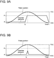
- FIG. 9A is a graph showing a change in the chamber pressure during normal operation of the hydraulic motor
- FIG. 9B is a graph showing a change in the chamber pressure when there is the latch failure described below in the hydraulic motor.
- the low-pressure valve 30 in the active cycle during normal operation of the hydraulic motor 10 (hydraulic machine), the low-pressure valve 30 is supplied with excitation current to be closed before the piston 22 reaches the top dead center, and then (from time t a in FIG. 9A ) the high-pressure valve 28 becomes openable as the pressure of the working chamber 24 increases due to the piston 22 moving toward the top dead center.
- P H in FIGs. 9A and 9B represents the pressure in the high-pressure line 12
- P L represents the pressure in the low-pressure line 14.
- the high-pressure valve 28 and the low-pressure valve 30 are normal, it is possible to intentionally cause the above latch fail by retarding the supply-start timing of the excitation current to the low-pressure valve 30.
- the latch failure does not occur even if the supply-start timing of the excitation current to the low-pressure valve 30 is retarded, because the low-pressure valve 30 closes before the piston 22 passes through the top dead center, which increases the chamber pressure and opens the high-pressure valve 28.
- the second abnormality determination part 116 it is possible to detect self pumping on the basis of whether latch failure is occurring. Further, it is possible to improve the reliability of the abnormality determination for the hydraulic motor 10 (hydraulic machine) by detecting self pumping in each abnormality determination part using both of the first abnormality determination part 114 and the second abnormality determination part 116.
- the wind turbine power generating apparatus 1 includes a pitch drive (pitch drive device) 60 for adjusting the pitch angle of the at least one blade 2.
- the controller 111 includes a pitch control part 113 which controls the hydraulic motor 10 so as to reduce the displacement of the hydraulic motor 10 and controls the pitch drive 60 so as to reduce the wind energy to be extracted by the at least one blade 2, if the first abnormality determination part 114 of the diagnosis system 70 detects abnormality of the hydraulic motor 10.
- the displacement of the hydraulic motor 10 having the above configuration depends on the ratio of cylinders 20 performing the active cycle or the inactive cycle among a plurality of cylinders 20 constituting the hydraulic motor 10.
- the ratio of the cylinders 20 performing the inactive cycle among all cylinders 20 of the hydraulic motor 10 is to be increased.
- the valve control part 112 may control the high-pressure valve 28 to be kept closed and the low-pressure valve 30 to be kept open, during a cycle in which the piston 22 starts the bottom dead center and returns to the same via the top dead center so as not to increase the pressure of the working oil, thereby causing some cylinders 20 to perform the inactive cycle.
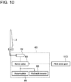
- FIG. 10 is a configuration example of a pitch drive.
- the pitch drive 60 illustrated in FIG. 10 includes a hydraulic cylinder 62, a servo valve 64, a hydraulic source 66 and an accumulator 68, and is accommodated in a hub for housing the hydraulic transmission 7 and the like of the wind turbine power generating apparatus 1 illustrated in FIG. 1 .
- the servo valve 64 adjusts, under the control of the pitch control part 113, the amount of high-pressure oil to be supplied to the hydraulic cylinder 62, the high pressure oil including high-pressure oil generated by the hydraulic source 66 and high-pressure oil stored in the accumulator 68, so as to achieve a desired pitch angle of the at least one blade 2.
- the pitch drive 60 is controlled by the pitch control part 113 to adjust the pitch angle of the at least one blade 2 and decrease the rotation speed of the rotor 3, thereby reducing the rotation speed of the hydraulic pump 8.
- the rotation speed of the hydraulic pump 8 and/or the hydraulic motor 10 is reduced by decreasing the displacement of the hydraulic pump 8 and/or the hydraulic motor 10, while the pitch drive 60 is used to apply an aerodynamic braking force to the rotor 3 to reduce the rotation speed of the hydraulic pump 8. In this way, it is possible to reduce the wind energy to be extracted by the at least one blade 2.
- the displacement of the hydraulic motor 10 is not reduced to zero at once, but is gradually decreased, which makes it possible to stop the wind turbine power generating apparatus 1 while protecting the constituent members (e.g. the high-pressure valve 28 and the low-pressure valve 30) of the hydraulic motor 10.
- an expression of relative or absolute arrangement such as “in a direction”, “along a direction”, “parallel”, “orthogonal”, “centered”, “concentric” and “coaxial” shall not be construed as indicating only the arrangement in a strict literal sense, but also includes a state where the arrangement is relatively displaced by a tolerance, or by an angle or a distance whereby it is possible to achieve the same function.
- an expression of an equal state such as “same” “equal” and “uniform” shall not be construed as indicating only the state in which the feature is strictly equal, but also includes a state in which there is a tolerance or a difference that can still achieve the same function.
- an expression of a shape such as a rectangular shape or a cylindrical shape shall not be construed as only the geometrically strict shape, but also includes a shape with unevenness or chamfered corners within the range in which the same effect can be achieved.
- an expression such as “comprise”, “include”, “have”, “contain” and “constitute” are not intended to be exclusive of other components.
Landscapes
- Engineering & Computer Science (AREA)
- Mechanical Engineering (AREA)
- General Engineering & Computer Science (AREA)
- Combustion & Propulsion (AREA)
- Chemical & Material Sciences (AREA)
- Life Sciences & Earth Sciences (AREA)
- Sustainable Development (AREA)
- Sustainable Energy (AREA)
- Power Engineering (AREA)
- Wind Motors (AREA)
- Testing Of Devices, Machine Parts, Or Other Structures Thereof (AREA)
- Fluid-Pressure Circuits (AREA)
- Control Of Positive-Displacement Pumps (AREA)
Applications Claiming Priority (1)
| Application Number | Priority Date | Filing Date | Title |
|---|---|---|---|
| JP2015118534A JP6308977B2 (ja) | 2015-06-11 | 2015-06-11 | 油圧機械の診断システム、油圧機械及び風力発電装置並びに油圧機械の診断方法 |
Publications (2)
| Publication Number | Publication Date |
|---|---|
| EP3104005A1 true EP3104005A1 (fr) | 2016-12-14 |
| EP3104005B1 EP3104005B1 (fr) | 2021-08-11 |
Family
ID=55310724
Family Applications (1)
| Application Number | Title | Priority Date | Filing Date |
|---|---|---|---|
| EP16154339.2A Active EP3104005B1 (fr) | 2015-06-11 | 2016-02-04 | Système de diagnostic pour machine hydraulique, une machine hydraulique, une appareil de génération d'énergie éolienne et une procédé de diagnostic de machine hydraulique |
Country Status (2)
| Country | Link |
|---|---|
| EP (1) | EP3104005B1 (fr) |
| JP (1) | JP6308977B2 (fr) |
Cited By (3)
| Publication number | Priority date | Publication date | Assignee | Title |
|---|---|---|---|---|
| CN115837772A (zh) * | 2022-12-23 | 2023-03-24 | 东风汽车股份有限公司 | 一种压力机工作台夹紧器异常处理方法及装置及压力机 |
| US11946470B2 (en) | 2017-03-17 | 2024-04-02 | Ebara Corporation | Information processing apparatus, information processing system, information processing method, program, substrate processing apparatus, criterion data determination apparatus, and criterion data determination method |
| US12577952B2 (en) | 2017-03-17 | 2026-03-17 | Ebara Corporation | Information processing apparatus, information processing system, information processing method, program, substrate processing apparatus, criterion data determination apparatus, and criterion data determination method |
Families Citing this family (5)
| Publication number | Priority date | Publication date | Assignee | Title |
|---|---|---|---|---|
| JP7046503B2 (ja) * | 2017-05-18 | 2022-04-04 | 株式会社荏原製作所 | 情報処理装置、基準データ決定装置、情報処理方法、基準データ決定方法及びプログラム |
| CN108457687A (zh) * | 2018-03-16 | 2018-08-28 | 河北工程大学 | 一种新型节能煤矿压风机 |
| JP2021011826A (ja) * | 2019-07-03 | 2021-02-04 | いすゞ自動車株式会社 | 作動機械 |
| CN111752256B (zh) * | 2019-11-28 | 2022-12-06 | 机械工业仪器仪表综合技术经济研究所 | 锻造液压机远程故障诊断方法及系统 |
| JP7843216B2 (ja) * | 2022-11-29 | 2026-04-09 | 三菱重工業株式会社 | 風力発電設備用の異常診断システム、および、異常診断方法 |
Citations (7)
| Publication number | Priority date | Publication date | Assignee | Title |
|---|---|---|---|---|
| US5846056A (en) * | 1995-04-07 | 1998-12-08 | Dhindsa; Jasbir S. | Reciprocating pump system and method for operating same |
| US20100040470A1 (en) | 2008-08-13 | 2010-02-18 | Jacob Johannes Nies | Wind energy system with fluid-working machine with non-symmetric actuation |
| GB2477996A (en) * | 2010-02-23 | 2011-08-24 | Artemis Intelligent Power Ltd | Fluid-Working Machine and Method of Operating a Fluid-Working Machine |
| WO2011104547A2 (fr) | 2010-02-23 | 2011-09-01 | Artemis Intelligent Power Limited | Réglage des soupapes d'une machine à fluide de travail |
| WO2011104548A2 (fr) * | 2010-02-23 | 2011-09-01 | Artemis Intelligent Power Limited | Machine à fluide de travail et son procédé de fonctionnement |
| WO2012073389A1 (fr) * | 2010-11-30 | 2012-06-07 | Mitsubishi Heavy Industries, Ltd. | Dispositif d'extraction d'énergie renouvelable, tel qu'une turbine éolienne à transmission hydraulique |
| EP2631477A2 (fr) * | 2012-02-23 | 2013-08-28 | Mitsubishi Heavy Industries, Ltd. | Procédé et système de surveillance pour éolienne |
Family Cites Families (3)
| Publication number | Priority date | Publication date | Assignee | Title |
|---|---|---|---|---|
| JP4479125B2 (ja) * | 2001-05-29 | 2010-06-09 | トヨタ自動車株式会社 | 圧力関連ユニット検査方法および圧力関連ユニット検査システム |
| CN103003567A (zh) * | 2010-11-30 | 2013-03-27 | 三菱重工业株式会社 | 风轮发电机和潮流发电机及其操作方法 |
| WO2014118907A1 (fr) * | 2013-01-30 | 2014-08-07 | 三菱重工業株式会社 | Système de diagnostic et procédé de diagnostic pour dispositif de production d'énergie éolienne |
-
2015
- 2015-06-11 JP JP2015118534A patent/JP6308977B2/ja not_active Expired - Fee Related
-
2016
- 2016-02-04 EP EP16154339.2A patent/EP3104005B1/fr active Active
Patent Citations (7)
| Publication number | Priority date | Publication date | Assignee | Title |
|---|---|---|---|---|
| US5846056A (en) * | 1995-04-07 | 1998-12-08 | Dhindsa; Jasbir S. | Reciprocating pump system and method for operating same |
| US20100040470A1 (en) | 2008-08-13 | 2010-02-18 | Jacob Johannes Nies | Wind energy system with fluid-working machine with non-symmetric actuation |
| GB2477996A (en) * | 2010-02-23 | 2011-08-24 | Artemis Intelligent Power Ltd | Fluid-Working Machine and Method of Operating a Fluid-Working Machine |
| WO2011104547A2 (fr) | 2010-02-23 | 2011-09-01 | Artemis Intelligent Power Limited | Réglage des soupapes d'une machine à fluide de travail |
| WO2011104548A2 (fr) * | 2010-02-23 | 2011-09-01 | Artemis Intelligent Power Limited | Machine à fluide de travail et son procédé de fonctionnement |
| WO2012073389A1 (fr) * | 2010-11-30 | 2012-06-07 | Mitsubishi Heavy Industries, Ltd. | Dispositif d'extraction d'énergie renouvelable, tel qu'une turbine éolienne à transmission hydraulique |
| EP2631477A2 (fr) * | 2012-02-23 | 2013-08-28 | Mitsubishi Heavy Industries, Ltd. | Procédé et système de surveillance pour éolienne |
Cited By (4)
| Publication number | Priority date | Publication date | Assignee | Title |
|---|---|---|---|---|
| US11946470B2 (en) | 2017-03-17 | 2024-04-02 | Ebara Corporation | Information processing apparatus, information processing system, information processing method, program, substrate processing apparatus, criterion data determination apparatus, and criterion data determination method |
| US12577952B2 (en) | 2017-03-17 | 2026-03-17 | Ebara Corporation | Information processing apparatus, information processing system, information processing method, program, substrate processing apparatus, criterion data determination apparatus, and criterion data determination method |
| CN115837772A (zh) * | 2022-12-23 | 2023-03-24 | 东风汽车股份有限公司 | 一种压力机工作台夹紧器异常处理方法及装置及压力机 |
| CN115837772B (zh) * | 2022-12-23 | 2024-04-19 | 东风汽车股份有限公司 | 一种压力机工作台夹紧器异常处理方法及装置及压力机 |
Also Published As
| Publication number | Publication date |
|---|---|
| JP2017003465A (ja) | 2017-01-05 |
| EP3104005B1 (fr) | 2021-08-11 |
| JP6308977B2 (ja) | 2018-04-11 |
Similar Documents
| Publication | Publication Date | Title |
|---|---|---|
| EP3104005A1 (fr) | Système de diagnostic pour machine hydraulique, une machine hydraulique, une appareil de génération d'énergie éolienne et une procédé de diagnostic de machine hydraulique | |
| EP2889480B1 (fr) | Système de diagnostic et procédé de diagnostic pour machine hydraulique et transmission hydraulique et générateur de turbine éolienne | |
| US10794362B2 (en) | Method and system for diagnosing wind turbine power generating apparatus | |
| JP7253387B2 (ja) | 油圧アクチュエータを有する物体の配置 | |
| US8624413B2 (en) | Regeneration energy type electric generation apparatus and its rotor fixing method | |
| US20130134335A1 (en) | Method and Device for Controlling a Valve | |
| CN102312882A (zh) | 用于监测液压回路中的构件的方法、监测装置和流体涡轮 | |
| US20130251499A1 (en) | Energy extraction device and operating method | |
| KR20130138757A (ko) | 유압 밸브의 폐쇄 지점에 도달했을 때를 감지하기 위한 방법 및 장치 | |
| EP2896830B1 (fr) | Machine hydraulique et appareil de génération de puissance | |
| JP5818967B2 (ja) | モータリングモードでの運転が可能な油圧ポンプを備える再生可能エネルギー型発電装置 | |
| CN112648168B (zh) | 往返式压缩膨胀机 | |
| EP3211276B1 (fr) | Machine hydraulique avec système de diagnostic, appareil de génération de puissance de type à énergie renouvelable et procédé de diagnostic de machine hydraulique | |
| EP3211395B1 (fr) | Procédé et système de diagnostic pour machine hydraulique, machine hydraulique et générateur de puissance de type à énergie renouvelable | |
| EP3098450B1 (fr) | Procédé et appareil de diagnostic de machine hydraulique, appareil de génération de puissance de type à énergie renouvelable et méthode de diagnostic associée | |
| EP2873870A1 (fr) | Ensemble piston de distributeur, machine hydraulique et appareil de génération de puissance | |
| EP3211275A1 (fr) | Procédé et système de diagnostic pour machine hydraulique, machine hydraulique et générateur de puissance de type à énergie renouvelable | |
| EP3287636B1 (fr) | Procédé de fonctionnement et système de commande de fonctionnement pour moteur hydraulique, transmission hydraulique et appareil de production de puissance de type à énergie renouvelable | |
| EP3211232B1 (fr) | Système et procédé de diagnostic de machine hydraulique, machine hydraulique, transmission hydraulique et générateur de type à énergie renouvelable | |
| EP3171061B1 (fr) | Bloc de vanne, machine à fluide et appareil de génération d'énergie à énergie renouvelable |
Legal Events
| Date | Code | Title | Description |
|---|---|---|---|
| PUAI | Public reference made under article 153(3) epc to a published international application that has entered the european phase |
Free format text: ORIGINAL CODE: 0009012 |
|
| STAA | Information on the status of an ep patent application or granted ep patent |
Free format text: STATUS: THE APPLICATION HAS BEEN PUBLISHED |
|
| AK | Designated contracting states |
Kind code of ref document: A1 Designated state(s): AL AT BE BG CH CY CZ DE DK EE ES FI FR GB GR HR HU IE IS IT LI LT LU LV MC MK MT NL NO PL PT RO RS SE SI SK SM TR |
|
| AX | Request for extension of the european patent |
Extension state: BA ME |
|
| STAA | Information on the status of an ep patent application or granted ep patent |
Free format text: STATUS: REQUEST FOR EXAMINATION WAS MADE |
|
| 17P | Request for examination filed |
Effective date: 20170125 |
|
| RBV | Designated contracting states (corrected) |
Designated state(s): AL AT BE BG CH CY CZ DE DK EE ES FI FR GB GR HR HU IE IS IT LI LT LU LV MC MK MT NL NO PL PT RO RS SE SI SK SM TR |
|
| REG | Reference to a national code |
Ref country code: DE Ref legal event code: R079 Ref document number: 602016061869 Country of ref document: DE Free format text: PREVIOUS MAIN CLASS: F04B0001040000 Ipc: F04B0001040800 |
|
| GRAP | Despatch of communication of intention to grant a patent |
Free format text: ORIGINAL CODE: EPIDOSNIGR1 |
|
| STAA | Information on the status of an ep patent application or granted ep patent |
Free format text: STATUS: GRANT OF PATENT IS INTENDED |
|
| RIC1 | Information provided on ipc code assigned before grant |
Ipc: F04B 49/22 20060101ALI20210226BHEP Ipc: F04B 51/00 20060101ALI20210226BHEP Ipc: F04B 1/0408 20200101AFI20210226BHEP Ipc: F03C 1/28 20060101ALI20210226BHEP Ipc: F04B 17/02 20060101ALI20210226BHEP Ipc: F03D 17/00 20160101ALI20210226BHEP Ipc: F03D 9/28 20160101ALI20210226BHEP Ipc: F04B 53/10 20060101ALI20210226BHEP |
|
| INTG | Intention to grant announced |
Effective date: 20210401 |
|
| GRAS | Grant fee paid |
Free format text: ORIGINAL CODE: EPIDOSNIGR3 |
|
| GRAA | (expected) grant |
Free format text: ORIGINAL CODE: 0009210 |
|
| STAA | Information on the status of an ep patent application or granted ep patent |
Free format text: STATUS: THE PATENT HAS BEEN GRANTED |
|
| AK | Designated contracting states |
Kind code of ref document: B1 Designated state(s): AL AT BE BG CH CY CZ DE DK EE ES FI FR GB GR HR HU IE IS IT LI LT LU LV MC MK MT NL NO PL PT RO RS SE SI SK SM TR |
|
| REG | Reference to a national code |
Ref country code: CH Ref legal event code: EP |
|
| REG | Reference to a national code |
Ref country code: DE Ref legal event code: R096 Ref document number: 602016061869 Country of ref document: DE |
|
| REG | Reference to a national code |
Ref country code: IE Ref legal event code: FG4D Ref country code: AT Ref legal event code: REF Ref document number: 1419634 Country of ref document: AT Kind code of ref document: T Effective date: 20210915 |
|
| REG | Reference to a national code |
Ref country code: LT Ref legal event code: MG9D |
|
| REG | Reference to a national code |
Ref country code: NL Ref legal event code: MP Effective date: 20210811 |
|
| REG | Reference to a national code |
Ref country code: AT Ref legal event code: MK05 Ref document number: 1419634 Country of ref document: AT Kind code of ref document: T Effective date: 20210811 |
|
| PG25 | Lapsed in a contracting state [announced via postgrant information from national office to epo] |
Ref country code: LT Free format text: LAPSE BECAUSE OF FAILURE TO SUBMIT A TRANSLATION OF THE DESCRIPTION OR TO PAY THE FEE WITHIN THE PRESCRIBED TIME-LIMIT Effective date: 20210811 Ref country code: BG Free format text: LAPSE BECAUSE OF FAILURE TO SUBMIT A TRANSLATION OF THE DESCRIPTION OR TO PAY THE FEE WITHIN THE PRESCRIBED TIME-LIMIT Effective date: 20211111 Ref country code: AT Free format text: LAPSE BECAUSE OF FAILURE TO SUBMIT A TRANSLATION OF THE DESCRIPTION OR TO PAY THE FEE WITHIN THE PRESCRIBED TIME-LIMIT Effective date: 20210811 Ref country code: ES Free format text: LAPSE BECAUSE OF FAILURE TO SUBMIT A TRANSLATION OF THE DESCRIPTION OR TO PAY THE FEE WITHIN THE PRESCRIBED TIME-LIMIT Effective date: 20210811 Ref country code: FI Free format text: LAPSE BECAUSE OF FAILURE TO SUBMIT A TRANSLATION OF THE DESCRIPTION OR TO PAY THE FEE WITHIN THE PRESCRIBED TIME-LIMIT Effective date: 20210811 Ref country code: PT Free format text: LAPSE BECAUSE OF FAILURE TO SUBMIT A TRANSLATION OF THE DESCRIPTION OR TO PAY THE FEE WITHIN THE PRESCRIBED TIME-LIMIT Effective date: 20211213 Ref country code: NO Free format text: LAPSE BECAUSE OF FAILURE TO SUBMIT A TRANSLATION OF THE DESCRIPTION OR TO PAY THE FEE WITHIN THE PRESCRIBED TIME-LIMIT Effective date: 20211111 Ref country code: HR Free format text: LAPSE BECAUSE OF FAILURE TO SUBMIT A TRANSLATION OF THE DESCRIPTION OR TO PAY THE FEE WITHIN THE PRESCRIBED TIME-LIMIT Effective date: 20210811 Ref country code: RS Free format text: LAPSE BECAUSE OF FAILURE TO SUBMIT A TRANSLATION OF THE DESCRIPTION OR TO PAY THE FEE WITHIN THE PRESCRIBED TIME-LIMIT Effective date: 20210811 Ref country code: SE Free format text: LAPSE BECAUSE OF FAILURE TO SUBMIT A TRANSLATION OF THE DESCRIPTION OR TO PAY THE FEE WITHIN THE PRESCRIBED TIME-LIMIT Effective date: 20210811 |
|
| PG25 | Lapsed in a contracting state [announced via postgrant information from national office to epo] |
Ref country code: PL Free format text: LAPSE BECAUSE OF FAILURE TO SUBMIT A TRANSLATION OF THE DESCRIPTION OR TO PAY THE FEE WITHIN THE PRESCRIBED TIME-LIMIT Effective date: 20210811 Ref country code: LV Free format text: LAPSE BECAUSE OF FAILURE TO SUBMIT A TRANSLATION OF THE DESCRIPTION OR TO PAY THE FEE WITHIN THE PRESCRIBED TIME-LIMIT Effective date: 20210811 Ref country code: GR Free format text: LAPSE BECAUSE OF FAILURE TO SUBMIT A TRANSLATION OF THE DESCRIPTION OR TO PAY THE FEE WITHIN THE PRESCRIBED TIME-LIMIT Effective date: 20211112 |
|
| PG25 | Lapsed in a contracting state [announced via postgrant information from national office to epo] |
Ref country code: NL Free format text: LAPSE BECAUSE OF FAILURE TO SUBMIT A TRANSLATION OF THE DESCRIPTION OR TO PAY THE FEE WITHIN THE PRESCRIBED TIME-LIMIT Effective date: 20210811 |
|
| PG25 | Lapsed in a contracting state [announced via postgrant information from national office to epo] |
Ref country code: DK Free format text: LAPSE BECAUSE OF FAILURE TO SUBMIT A TRANSLATION OF THE DESCRIPTION OR TO PAY THE FEE WITHIN THE PRESCRIBED TIME-LIMIT Effective date: 20210811 |
|
| REG | Reference to a national code |
Ref country code: DE Ref legal event code: R097 Ref document number: 602016061869 Country of ref document: DE |
|
| PG25 | Lapsed in a contracting state [announced via postgrant information from national office to epo] |
Ref country code: SM Free format text: LAPSE BECAUSE OF FAILURE TO SUBMIT A TRANSLATION OF THE DESCRIPTION OR TO PAY THE FEE WITHIN THE PRESCRIBED TIME-LIMIT Effective date: 20210811 Ref country code: SK Free format text: LAPSE BECAUSE OF FAILURE TO SUBMIT A TRANSLATION OF THE DESCRIPTION OR TO PAY THE FEE WITHIN THE PRESCRIBED TIME-LIMIT Effective date: 20210811 Ref country code: RO Free format text: LAPSE BECAUSE OF FAILURE TO SUBMIT A TRANSLATION OF THE DESCRIPTION OR TO PAY THE FEE WITHIN THE PRESCRIBED TIME-LIMIT Effective date: 20210811 Ref country code: EE Free format text: LAPSE BECAUSE OF FAILURE TO SUBMIT A TRANSLATION OF THE DESCRIPTION OR TO PAY THE FEE WITHIN THE PRESCRIBED TIME-LIMIT Effective date: 20210811 Ref country code: CZ Free format text: LAPSE BECAUSE OF FAILURE TO SUBMIT A TRANSLATION OF THE DESCRIPTION OR TO PAY THE FEE WITHIN THE PRESCRIBED TIME-LIMIT Effective date: 20210811 Ref country code: AL Free format text: LAPSE BECAUSE OF FAILURE TO SUBMIT A TRANSLATION OF THE DESCRIPTION OR TO PAY THE FEE WITHIN THE PRESCRIBED TIME-LIMIT Effective date: 20210811 |
|
| PLBE | No opposition filed within time limit |
Free format text: ORIGINAL CODE: 0009261 |
|
| STAA | Information on the status of an ep patent application or granted ep patent |
Free format text: STATUS: NO OPPOSITION FILED WITHIN TIME LIMIT |
|
| 26N | No opposition filed |
Effective date: 20220512 |
|
| PG25 | Lapsed in a contracting state [announced via postgrant information from national office to epo] |
Ref country code: IT Free format text: LAPSE BECAUSE OF FAILURE TO SUBMIT A TRANSLATION OF THE DESCRIPTION OR TO PAY THE FEE WITHIN THE PRESCRIBED TIME-LIMIT Effective date: 20210811 |
|
| PG25 | Lapsed in a contracting state [announced via postgrant information from national office to epo] |
Ref country code: SI Free format text: LAPSE BECAUSE OF FAILURE TO SUBMIT A TRANSLATION OF THE DESCRIPTION OR TO PAY THE FEE WITHIN THE PRESCRIBED TIME-LIMIT Effective date: 20210811 |
|
| PG25 | Lapsed in a contracting state [announced via postgrant information from national office to epo] |
Ref country code: MC Free format text: LAPSE BECAUSE OF FAILURE TO SUBMIT A TRANSLATION OF THE DESCRIPTION OR TO PAY THE FEE WITHIN THE PRESCRIBED TIME-LIMIT Effective date: 20210811 |
|
| REG | Reference to a national code |
Ref country code: CH Ref legal event code: PL |
|
| REG | Reference to a national code |
Ref country code: BE Ref legal event code: MM Effective date: 20220228 |
|
| PG25 | Lapsed in a contracting state [announced via postgrant information from national office to epo] |
Ref country code: LU Free format text: LAPSE BECAUSE OF NON-PAYMENT OF DUE FEES Effective date: 20220204 |
|
| PG25 | Lapsed in a contracting state [announced via postgrant information from national office to epo] |
Ref country code: LI Free format text: LAPSE BECAUSE OF NON-PAYMENT OF DUE FEES Effective date: 20220228 Ref country code: IE Free format text: LAPSE BECAUSE OF NON-PAYMENT OF DUE FEES Effective date: 20220204 Ref country code: CH Free format text: LAPSE BECAUSE OF NON-PAYMENT OF DUE FEES Effective date: 20220228 |
|
| PGFP | Annual fee paid to national office [announced via postgrant information from national office to epo] |
Ref country code: GB Payment date: 20221230 Year of fee payment: 8 |
|
| PG25 | Lapsed in a contracting state [announced via postgrant information from national office to epo] |
Ref country code: BE Free format text: LAPSE BECAUSE OF NON-PAYMENT OF DUE FEES Effective date: 20220228 |
|
| PGFP | Annual fee paid to national office [announced via postgrant information from national office to epo] |
Ref country code: FR Payment date: 20230110 Year of fee payment: 8 |
|
| PGFP | Annual fee paid to national office [announced via postgrant information from national office to epo] |
Ref country code: DE Payment date: 20221229 Year of fee payment: 8 |
|
| PG25 | Lapsed in a contracting state [announced via postgrant information from national office to epo] |
Ref country code: HU Free format text: LAPSE BECAUSE OF FAILURE TO SUBMIT A TRANSLATION OF THE DESCRIPTION OR TO PAY THE FEE WITHIN THE PRESCRIBED TIME-LIMIT; INVALID AB INITIO Effective date: 20160204 |
|
| PG25 | Lapsed in a contracting state [announced via postgrant information from national office to epo] |
Ref country code: MK Free format text: LAPSE BECAUSE OF FAILURE TO SUBMIT A TRANSLATION OF THE DESCRIPTION OR TO PAY THE FEE WITHIN THE PRESCRIBED TIME-LIMIT Effective date: 20210811 Ref country code: CY Free format text: LAPSE BECAUSE OF FAILURE TO SUBMIT A TRANSLATION OF THE DESCRIPTION OR TO PAY THE FEE WITHIN THE PRESCRIBED TIME-LIMIT Effective date: 20210811 |
|
| REG | Reference to a national code |
Ref country code: DE Ref legal event code: R119 Ref document number: 602016061869 Country of ref document: DE |
|
| PG25 | Lapsed in a contracting state [announced via postgrant information from national office to epo] |
Ref country code: MT Free format text: LAPSE BECAUSE OF FAILURE TO SUBMIT A TRANSLATION OF THE DESCRIPTION OR TO PAY THE FEE WITHIN THE PRESCRIBED TIME-LIMIT Effective date: 20210811 |
|
| GBPC | Gb: european patent ceased through non-payment of renewal fee |
Effective date: 20240204 |
|
| PG25 | Lapsed in a contracting state [announced via postgrant information from national office to epo] |
Ref country code: DE Free format text: LAPSE BECAUSE OF NON-PAYMENT OF DUE FEES Effective date: 20240903 |
|
| PG25 | Lapsed in a contracting state [announced via postgrant information from national office to epo] |
Ref country code: GB Free format text: LAPSE BECAUSE OF NON-PAYMENT OF DUE FEES Effective date: 20240204 |
|
| PG25 | Lapsed in a contracting state [announced via postgrant information from national office to epo] |
Ref country code: FR Free format text: LAPSE BECAUSE OF NON-PAYMENT OF DUE FEES Effective date: 20240229 |
|
| PG25 | Lapsed in a contracting state [announced via postgrant information from national office to epo] |
Ref country code: GB Free format text: LAPSE BECAUSE OF NON-PAYMENT OF DUE FEES Effective date: 20240204 Ref country code: FR Free format text: LAPSE BECAUSE OF NON-PAYMENT OF DUE FEES Effective date: 20240229 Ref country code: DE Free format text: LAPSE BECAUSE OF NON-PAYMENT OF DUE FEES Effective date: 20240903 |
|
| PG25 | Lapsed in a contracting state [announced via postgrant information from national office to epo] |
Ref country code: TR Free format text: LAPSE BECAUSE OF FAILURE TO SUBMIT A TRANSLATION OF THE DESCRIPTION OR TO PAY THE FEE WITHIN THE PRESCRIBED TIME-LIMIT Effective date: 20210811 |