EP3104065A1 - Bremsleuchte für kfz-rücklicht, die an mehrere typen von leuchtquellen angepasst werden kann - Google Patents
Bremsleuchte für kfz-rücklicht, die an mehrere typen von leuchtquellen angepasst werden kann Download PDFInfo
- Publication number
- EP3104065A1 EP3104065A1 EP16173383.7A EP16173383A EP3104065A1 EP 3104065 A1 EP3104065 A1 EP 3104065A1 EP 16173383 A EP16173383 A EP 16173383A EP 3104065 A1 EP3104065 A1 EP 3104065A1
- Authority
- EP
- European Patent Office
- Prior art keywords
- printed circuit
- face
- lens
- distance
- support means
- Prior art date
- Legal status (The legal status is an assumption and is not a legal conclusion. Google has not performed a legal analysis and makes no representation as to the accuracy of the status listed.)
- Granted
Links
Images

Classifications
-
- B—PERFORMING OPERATIONS; TRANSPORTING
- B60—VEHICLES IN GENERAL
- B60Q—ARRANGEMENT OF SIGNALLING OR LIGHTING DEVICES, THE MOUNTING OR SUPPORTING THEREOF OR CIRCUITS THEREFOR, FOR VEHICLES IN GENERAL
- B60Q1/00—Arrangement of optical signalling or lighting devices, the mounting or supporting thereof or circuits therefor
- B60Q1/26—Arrangement of optical signalling or lighting devices, the mounting or supporting thereof or circuits therefor the devices being primarily intended to indicate the vehicle, or parts thereof, or to give signals, to other traffic
- B60Q1/2661—Arrangement of optical signalling or lighting devices, the mounting or supporting thereof or circuits therefor the devices being primarily intended to indicate the vehicle, or parts thereof, or to give signals, to other traffic mounted on parts having other functions
- B60Q1/268—Arrangement of optical signalling or lighting devices, the mounting or supporting thereof or circuits therefor the devices being primarily intended to indicate the vehicle, or parts thereof, or to give signals, to other traffic mounted on parts having other functions on windscreens or windows
-
- F—MECHANICAL ENGINEERING; LIGHTING; HEATING; WEAPONS; BLASTING
- F21—LIGHTING
- F21S—NON-PORTABLE LIGHTING DEVICES; SYSTEMS THEREOF; VEHICLE LIGHTING DEVICES SPECIALLY ADAPTED FOR VEHICLE EXTERIORS
- F21S43/00—Signalling devices specially adapted for vehicle exteriors, e.g. brake lamps, direction indicator lights or reversing lights
- F21S43/10—Signalling devices specially adapted for vehicle exteriors, e.g. brake lamps, direction indicator lights or reversing lights characterised by the light source
- F21S43/19—Attachment of light sources or lamp holders
-
- B—PERFORMING OPERATIONS; TRANSPORTING
- B60—VEHICLES IN GENERAL
- B60Q—ARRANGEMENT OF SIGNALLING OR LIGHTING DEVICES, THE MOUNTING OR SUPPORTING THEREOF OR CIRCUITS THEREFOR, FOR VEHICLES IN GENERAL
- B60Q1/00—Arrangement of optical signalling or lighting devices, the mounting or supporting thereof or circuits therefor
- B60Q1/26—Arrangement of optical signalling or lighting devices, the mounting or supporting thereof or circuits therefor the devices being primarily intended to indicate the vehicle, or parts thereof, or to give signals, to other traffic
- B60Q1/44—Arrangement of optical signalling or lighting devices, the mounting or supporting thereof or circuits therefor the devices being primarily intended to indicate the vehicle, or parts thereof, or to give signals, to other traffic for indicating braking action or preparation for braking, e.g. by detection of the foot approaching the brake pedal
-
- F—MECHANICAL ENGINEERING; LIGHTING; HEATING; WEAPONS; BLASTING
- F21—LIGHTING
- F21S—NON-PORTABLE LIGHTING DEVICES; SYSTEMS THEREOF; VEHICLE LIGHTING DEVICES SPECIALLY ADAPTED FOR VEHICLE EXTERIORS
- F21S43/00—Signalling devices specially adapted for vehicle exteriors, e.g. brake lamps, direction indicator lights or reversing lights
- F21S43/10—Signalling devices specially adapted for vehicle exteriors, e.g. brake lamps, direction indicator lights or reversing lights characterised by the light source
- F21S43/13—Signalling devices specially adapted for vehicle exteriors, e.g. brake lamps, direction indicator lights or reversing lights characterised by the light source characterised by the type of light source
- F21S43/14—Light emitting diodes [LED]
-
- F—MECHANICAL ENGINEERING; LIGHTING; HEATING; WEAPONS; BLASTING
- F21—LIGHTING
- F21S—NON-PORTABLE LIGHTING DEVICES; SYSTEMS THEREOF; VEHICLE LIGHTING DEVICES SPECIALLY ADAPTED FOR VEHICLE EXTERIORS
- F21S43/00—Signalling devices specially adapted for vehicle exteriors, e.g. brake lamps, direction indicator lights or reversing lights
- F21S43/10—Signalling devices specially adapted for vehicle exteriors, e.g. brake lamps, direction indicator lights or reversing lights characterised by the light source
- F21S43/19—Attachment of light sources or lamp holders
- F21S43/195—Details of lamp holders, terminals or connectors
-
- F—MECHANICAL ENGINEERING; LIGHTING; HEATING; WEAPONS; BLASTING
- F21—LIGHTING
- F21S—NON-PORTABLE LIGHTING DEVICES; SYSTEMS THEREOF; VEHICLE LIGHTING DEVICES SPECIALLY ADAPTED FOR VEHICLE EXTERIORS
- F21S43/00—Signalling devices specially adapted for vehicle exteriors, e.g. brake lamps, direction indicator lights or reversing lights
- F21S43/20—Signalling devices specially adapted for vehicle exteriors, e.g. brake lamps, direction indicator lights or reversing lights characterised by refractors, transparent cover plates, light guides or filters
- F21S43/26—Refractors, transparent cover plates, light guides or filters not provided in groups F21S43/235 - F21S43/255
-
- F—MECHANICAL ENGINEERING; LIGHTING; HEATING; WEAPONS; BLASTING
- F21—LIGHTING
- F21S—NON-PORTABLE LIGHTING DEVICES; SYSTEMS THEREOF; VEHICLE LIGHTING DEVICES SPECIALLY ADAPTED FOR VEHICLE EXTERIORS
- F21S43/00—Signalling devices specially adapted for vehicle exteriors, e.g. brake lamps, direction indicator lights or reversing lights
- F21S43/20—Signalling devices specially adapted for vehicle exteriors, e.g. brake lamps, direction indicator lights or reversing lights characterised by refractors, transparent cover plates, light guides or filters
- F21S43/27—Attachment thereof
-
- F—MECHANICAL ENGINEERING; LIGHTING; HEATING; WEAPONS; BLASTING
- F21—LIGHTING
- F21V—FUNCTIONAL FEATURES OR DETAILS OF LIGHTING DEVICES OR SYSTEMS THEREOF; STRUCTURAL COMBINATIONS OF LIGHTING DEVICES WITH OTHER ARTICLES, NOT OTHERWISE PROVIDED FOR
- F21V19/00—Fastening of light sources or lamp holders
- F21V19/001—Fastening of light sources or lamp holders the light sources being semiconductors devices, e.g. LEDs
- F21V19/003—Fastening of light source holders, e.g. of circuit boards or substrates holding light sources
-
- F—MECHANICAL ENGINEERING; LIGHTING; HEATING; WEAPONS; BLASTING
- F21—LIGHTING
- F21Y—INDEXING SCHEME ASSOCIATED WITH SUBCLASSES F21K, F21L, F21S and F21V, RELATING TO THE FORM OR THE KIND OF THE LIGHT SOURCES OR OF THE COLOUR OF THE LIGHT EMITTED
- F21Y2115/00—Light-generating elements of semiconductor light sources
- F21Y2115/10—Light-emitting diodes [LED]
Definitions
- the invention relates to the field of light signaling and / or lighting devices for a motor vehicle. More specifically, the invention deals with the field of rear stop lights in the high position of the rear window of a motor vehicle.
- a motor vehicle is generally equipped with an additional stop lamp in the rear central position.
- the fire ignites and arouses the attention of road users who follow.
- the stop light Being arranged in raised position, for example in the upper part of a rear window, the stop light becomes visible by a queue of users. In this way, more successive users are informed of the speed change of the driver who brakes upstream. They can better anticipate the dangers, traffic conditions become safer.
- the stop light can be implemented in known manner in the opening of the trunk when the latter makes the rear window pivoting.
- the stop light can be attached to the ceiling of the passenger compartment.
- the stop light extends vertically from its support downwards. It illuminates through the rear window of the vehicle that receives it, while remaining discreet in the cabin.
- Such a device generally comprises one or more optical lenses associated with one or more light sources, for example of the electroluminescent diode LED type.
- the electronic assembly comprising the light sources is generally supported by a printed circuit board mounted at a predetermined location of the device. It is indeed undesirable to provide a plurality of devices for different configurations of the same vehicle model, especially for reasons of production efficiency and development costs associated therewith.
- the intensity of the perceived flow of the stop lamp it is often necessary to use LEDs of different types and of different power on the same vehicle model, depending on the configuration of the vehicle. Indeed, if the opacity of the rear window glass has an influence on the light transmission of the brake light, it is the same for the radius of curvature and the inclination of the ice.
- the device and in particular the optical lens, is generally adapted to a given type of LED or light source.
- the invention aims to overcome at least one of the problems posed by the prior art.
- the invention relates to a signaling device and / or lighting for a motor vehicle.
- the device comprises a printed circuit received by a support, the printed circuit comprising at least one light source.
- a transmitting face of the light source is oriented towards an optical lens of the device.
- the emitting face is generally perpendicular to the optical axis of the lens.
- the device is remarkable in that the support makes it possible to receive the printed circuit at at least two predetermined distinct distances with respect to the optical lens.
- At least one of the predetermined distances defined by the support may be such that the emitting face of the light source is at the focal length of the optical lens when the printed circuit is received at this distance.
- the support may preferably comprise first support means and second support means respectively for receiving the printed circuit at a first distance and at a second distance, greater than the first distance, with respect to the optical lens.
- the first and second support means may be configured to cooperate with the edge of the printed circuit.
- the support means may extend generally parallel to the optical axis of the lens and may be so as to cooperate with corresponding notches provided on the printed circuit.
- the printed circuit may comprise recesses or holes corresponding to the location of the second support means, and allowing them to pass through the printed circuit.
- the printed circuit may preferably comprise at least one light source of a first type on a first face, and / or at least one light source of a second type on a second opposite face.
- the height of the emitting face of a light source of the second type relative to the plane defined by the printed circuit may be greater than the corresponding height of the emitting face of a light source of the first type.
- the first predetermined distance by the support may be such that the emitting face of the light source of the first type is at the focal length of the optical lens when the printed circuit is received at the first distance, the first face being oriented towards the lens.
- a second distance predetermined by the support may preferably be greater than the first distance, and be such that the emitting face of the second type of light source is at the focal length of the optical lens when the printed circuit is received. at the second distance, the second face being oriented towards the lens.
- the first face of the printed circuit may preferentially include notches or recesses intended to cooperate with the first support means.
- the second face of the printed circuit may preferably comprise notches or recesses for cooperating with the second support means.
- the arrangement of the support means and notches or recesses of the printed circuit may be such that when the printed circuit is received at the first distance, the first face being oriented towards the lens, the second support means pass through the printed circuit. .
- the light sources of the first type may preferably be intended to emit a luminous flux different from the light sources of the second type.
- the optical lens and the support can be made of material.
- the light sources may preferably comprise a semiconductor element, in particular a light-emitting diode, LED.
- the device according to the invention may be a stop signal for rear window of a motor vehicle.
- the optical lens or lenses of the device define a fixed focal length of the device.
- the optical properties of the device are optimal.
- types of sources including different types of LEDs, are electronic components having different heights
- the invention provides a support for mounting different types of LEDs through their printed circuit at different predetermined distances from the lens. optical. The distances are advantageously chosen so that each distance corresponds to a type of LED intended to be used in the fire. This means that mounting a given type of LED at the predetermined distance associated therewith has the direct consequence that the emitting face of the LED is at the focal length of the optical lens.
- the support defining the predetermined distances is integral with the optical lens, which ensures that the distances are invariable during assembly of the device, since no alignment of other components with respect to the lens is necessary.
- First means of support of the device are able to maintain a printed circuit at a first distance, while second support means are able to maintain a printed circuit at a second distance.
- the same printed circuit may have on each of its two faces means for cooperating respectively with the first and second support means of the device.
- the same circuit board can be mounted at two predetermined distances by the device.
- One and / or the other of the faces of the printed circuit can then be populated with LEDs whose height is such that their emitting face is at the focal length with respect to the optical lens.
- the same printed circuit can be used to place two different types of LEDs at respectively optimum and predetermined positions relative to the optical lens. This is achieved without generating additional development costs and in particular without requiring the change of other components of the stop light, such as the optical lens.
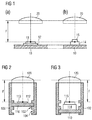
- the Figures 1a and 1b show two configurations of a device known from the prior art.
- the device of the figure 1a comprises an optical lens 20 and a non-illustrated support intended to receive a printed circuit 10 supporting a light source 12.
- the light source is for example a light-emitting diode, LED, in the form of an electronic chip, and having a transmitting face of light 13.
- the support serves to maintain the printed circuit at a predetermined distance which is such that the emitting face 13 of the source 12 is located at a distance F from the lens 20, corresponding to the focal length thereof.
- the support holds the circuit 10 and the source 12 in a plane generally perpendicular to the optical axis of the lens.
- the same device is used by mounting a different type of LED 14 on the printed circuit 10.
- the LED 14 is characterized by a greater height relative to the plane of the printed circuit 10, compared to the LED 12. Therefore, the face The emitter 15 is closer to the lens 20 and is not at the focal length F thereof.
- Such devices are commonly used in the prior art, although they necessarily generate deteriorated light performance in the case of Figure 1 b.
- the figure 2 shows a schematic illustration of an embodiment of the light device according to the invention.
- the device comprises a printed circuit 110 which is received by a support 100.
- the support is arranged to receive the printed circuit in a manner generally perpendicular to the optical axis of an optical lens 120, and this to at least two distinct distances relative to the position of the lens.
- the printed circuit comprises, on the side facing the lens 120, a light source 112 which is for example a light-emitting diode, LED, having an emitting surface 113.
- the arrangement is such that the emitting surface is generally perpendicular to the light source. optical axis and that the LED 112 emits light rays in the direction of the lens 120 when it is powered.
- the printed circuit may in particular comprise other electronic components, implementing, for example, means for controlling the power supply of the light source shown.
- such means can be deported with respect to the printed circuit and connected to it by an electrical connection.
- the power supply control means of the light source make it possible to convert a current of a given intensity, supplied for example by a battery of the motor vehicle equipped by the device, into a charge current of a different intensity. and able to feed the light source.
- Such means are well known in the art and their operation will not be described in more detail in the context of the present invention.
- the printed circuit board 110 comprises only one light source associated with an optical lens 120, it is obvious that the printed circuit may comprise a plurality of such sources each associated with an optical lens 120.
- the lens 120 defines a focal length F.
- the predetermined distances by the support 100 are such that at least one mounting distance is provided to receive the printed circuit carrying the source 112, so that the emitting face 113 of the source located at the distance F with respect to the optical lens 120.
- the support comprises arms which extend generally parallel to the optical axis of the lens 120 on two opposite sides thereof . Both arms include notches arranged symmetrically. One notch of one arm lies in the same plane perpendicular to the optical axis of the lens 120 as the corresponding notch of the other arm. The notches of one arm are oriented towards those of the other. These notches allow to support the edges of the printed circuit 110 as illustrated.
- the choice of the location of the notches is made according to the type of LED 112 to be used in the device, each type of LED potentially having a different height on the printed circuit.
- LEDs known in the art have, for example, circuit heights ranging from 0.6 mm to 1.8 mm.
- the notches or support means 102, 104 define two mounting distances of the printed circuit 110 relative to the lens 120. The first distance is adapted to the use of a LED of a first type 112. As illustrated by FIG. figure 3 , the second distance is adapted to the use of a LED of a second type 114 of greater height on the printed circuit 110.
- the support 100 allows the optimal mounting of the two types of LED 112, 114 which results in the placement respective emitting surfaces 113, 115 at the focal length of the lens 120, thereby optimizing the optical properties of the device. It is clear that the example shown can be scaled without departing from the scope of the invention, for example by providing three predetermined distances or more.
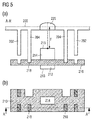
- the Figure 4 and 5 show another embodiment of the device according to the invention.
- the Figure 4a and 4b illustrate a first configuration of this device.
- a printed circuit 210 populated on its two faces with light emitting diodes 212, 214 of two different types is illustrated. In general, it is sufficient that one or other of the faces of the printed circuit 210 is populated with light emitting diodes of the type 212 or 214 respectively.
- the printed circuit 210 has the particularity that it is able to cooperate with the first support means 202 of the support 200 when the face carrying the diode 212 is oriented towards the lens 220, and when the opposite face carrying the diode 214 is oriented towards the lens 220, it is able to cooperate with the second support means 204.
- the distance predetermined by the first support means 202 is such that, when the printed circuit is received by these means, the emitting surface 213 of the diode 212 is at the focal length F with respect to the lens 220. This is illustrated by the figure 4a .
- the distance predetermined by the second support means 204 is such that, when the printed circuit is received by these means, the emitting surface 215 of the diode 213 is at the focal length F with respect to the lens 220. This is shown by the figure 5a .
- the orientation of the printed circuit is different in both cases, orienting either one of its two faces towards the lens.
- the support means 202, 204 extend in pairs in the form of arms or ribs on either side of the lens 220, generally parallel to the optical axis thereof.
- the first support means 202 extend a smaller distance than the second support means 204, thus defining a first distance smaller than a second distance.
- the printed circuit 210 comprises, on its first face carrying the first type of source 212, notches 217 placed so as to cooperate with the ends of the first support means 202.
- the printed circuit 210 further comprises holes, notches or through vias 216, allowing the second support means 204 to pass through the printed circuit when the circuit is received at the first distance. This is illustrated by the Figures 4a and 4b .
- notches or holes 216 are such that, when the printed circuit is turned back on itself so as to orient the light source 214 towards the lens 220, the second means 204 can not pass through the printed circuit 210. Indeed, notches 218 for cooperating with the end pieces of the second support means 204 are provided on the second face of the printed circuit. This is illustrated by the Figure 5a and 5b . A possible implementation is given by the figures 4 and 5 . It goes without saying that, depending on the geometry of the support means 202, 204, notches or holes are to be provided at different locations from those illustrated, in order to guarantee the operation described. Such modifications will nevertheless be within the abilities of those skilled in the art and remain within the scope of the present invention.
- the support 200 comprising the support means 202, 204 is preferably integral with the optical lens 220.
- the lens may for example be glass, other suitable materials being known to those skilled in the art.
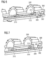
- the figure 6 shows another embodiment of the device according to the invention in a first configuration.
- the principle is identical to the one just described for the figures 4 and 5 respectively.
- a printed circuit 310 is supported in a first orientation with respect to a lens 320. In this orientation, a first face of the circuit comprising a first type of LED 312 is oriented towards the lens 320. The distance between the emitter face 313 of the LED and the lens 320 is predetermined by first support means 302.
- the printed circuit further comprises holes arranged to allow the passage of second support means 304, when the first face of the printed circuit is oriented towards the lens 320.
- the figure 7 takes over the device of the figure 6 in another configuration.
- the printed circuit 310 is turned on itself with respect to the configuration of the figure 6 .
- the second face, opposite to the first face, is oriented towards the lens 320.
- the second support means 304 do not pass through the printed circuit but define the distance between the emitting face 315 of the second type of diode 314 mounted on the second face of the printed circuit 310.
- the distances predetermined by the first and second support means are such that the emitting faces of the first and second types of LEDs can be at the fixed focal length of the lens 320.
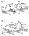
- the figure 8 shows another embodiment of the device according to the invention in a first configuration.
- a printed circuit 410 is supported in a first orientation with respect to a lens 420.
- a first face of the circuit comprising a first type of LED 412 is oriented towards the lens 420.
- the distance between the emitting face 413 of the LED and the lens 420 is predetermined by first support means 402.
- the first and second support means 402, 404 are integrally formed.
- the printed circuit comprises holes arranged to allow the passage of the second support means 404, when the first face of the printed circuit is oriented towards the lens 420.
- the first support means 402, wider than the second support means 404 rest on the contour of the holes.
- the figure 9 takes over the device of the figure 8 in a second configuration.
- the printed circuit 410 is returned to itself with respect to the configuration of the figure 8 .
- the second face opposite to the first face, is oriented towards the lens 420.
- the second support means 404 do not pass through the printed circuit but define the distance between the emitting face 415 of the second type of diode 414 mounted on the second face of the printed circuit 410.
- the distances predetermined by the first and second support means are such that the emitting faces of the first and second types of LEDs can be at the fixed focal length of the lens 420.
- the device is preferably a stop signal for rear window of a motor vehicle.
Landscapes
- Engineering & Computer Science (AREA)
- General Engineering & Computer Science (AREA)
- Mechanical Engineering (AREA)
- Physics & Mathematics (AREA)
- Microelectronics & Electronic Packaging (AREA)
- Optics & Photonics (AREA)
- Led Device Packages (AREA)
- Non-Portable Lighting Devices Or Systems Thereof (AREA)
Applications Claiming Priority (1)
| Application Number | Priority Date | Filing Date | Title |
|---|---|---|---|
| FR1555393A FR3037295B1 (fr) | 2015-06-12 | 2015-06-12 | Feu stop pour lunette arriere de vehicule automobile adaptable a plusieurs types de sources lumineuses |
Publications (2)
| Publication Number | Publication Date |
|---|---|
| EP3104065A1 true EP3104065A1 (de) | 2016-12-14 |
| EP3104065B1 EP3104065B1 (de) | 2023-03-15 |
Family
ID=54066041
Family Applications (1)
| Application Number | Title | Priority Date | Filing Date |
|---|---|---|---|
| EP16173383.7A Active EP3104065B1 (de) | 2015-06-12 | 2016-06-07 | Signal- und/oder beleuchtungsvorrichtung eines kraftfahrzeugs |
Country Status (3)
| Country | Link |
|---|---|
| US (1) | US10118540B2 (de) |
| EP (1) | EP3104065B1 (de) |
| FR (1) | FR3037295B1 (de) |
Families Citing this family (1)
| Publication number | Priority date | Publication date | Assignee | Title |
|---|---|---|---|---|
| EP4542107A1 (de) * | 2023-10-17 | 2025-04-23 | Goodrich Lighting Systems GmbH & Co. KG | Optikträgersystem für eine flugzeugleuchte, flugzeugleuchte mit optikträgersystem und flugzeug damit |
Citations (7)
| Publication number | Priority date | Publication date | Assignee | Title |
|---|---|---|---|---|
| DE10145963A1 (de) * | 2000-09-18 | 2002-04-04 | Koito Mfg Co Ltd | Fahrzeuglampen |
| JP2004045192A (ja) * | 2002-07-11 | 2004-02-12 | Kyoto Denkiki Kk | 照明装置 |
| US20040120160A1 (en) * | 2002-07-24 | 2004-06-24 | Koito Manufacturing Co., Ltd. | Vehicular lamp |
| US20060285348A1 (en) * | 2003-09-22 | 2006-12-21 | Valcamp David J | Vehicular light assembly |
| US20110273892A1 (en) * | 2010-05-07 | 2011-11-10 | Tyco Electronics Corporation | Solid state lighting assembly |
| KR20130032686A (ko) * | 2011-09-23 | 2013-04-02 | 현대모비스 주식회사 | 차량용 램프 장치. |
| DE102012107834A1 (de) * | 2012-08-24 | 2014-02-27 | SMR Patents S.à.r.l. | Beleuchtungseinrichtung und Rückblickeinrichtung |
-
2015
- 2015-06-12 FR FR1555393A patent/FR3037295B1/fr not_active Expired - Fee Related
-
2016
- 2016-06-07 US US15/175,277 patent/US10118540B2/en active Active
- 2016-06-07 EP EP16173383.7A patent/EP3104065B1/de active Active
Patent Citations (7)
| Publication number | Priority date | Publication date | Assignee | Title |
|---|---|---|---|---|
| DE10145963A1 (de) * | 2000-09-18 | 2002-04-04 | Koito Mfg Co Ltd | Fahrzeuglampen |
| JP2004045192A (ja) * | 2002-07-11 | 2004-02-12 | Kyoto Denkiki Kk | 照明装置 |
| US20040120160A1 (en) * | 2002-07-24 | 2004-06-24 | Koito Manufacturing Co., Ltd. | Vehicular lamp |
| US20060285348A1 (en) * | 2003-09-22 | 2006-12-21 | Valcamp David J | Vehicular light assembly |
| US20110273892A1 (en) * | 2010-05-07 | 2011-11-10 | Tyco Electronics Corporation | Solid state lighting assembly |
| KR20130032686A (ko) * | 2011-09-23 | 2013-04-02 | 현대모비스 주식회사 | 차량용 램프 장치. |
| DE102012107834A1 (de) * | 2012-08-24 | 2014-02-27 | SMR Patents S.à.r.l. | Beleuchtungseinrichtung und Rückblickeinrichtung |
Also Published As
| Publication number | Publication date |
|---|---|
| US20160362043A1 (en) | 2016-12-15 |
| FR3037295A1 (fr) | 2016-12-16 |
| US10118540B2 (en) | 2018-11-06 |
| EP3104065B1 (de) | 2023-03-15 |
| FR3037295B1 (fr) | 2018-10-12 |
Similar Documents
| Publication | Publication Date | Title |
|---|---|---|
| EP3181991B1 (de) | Kraftfahrzeug-beleuchtungsmodul mit kombinerter abblend- und fernlichtfunktion und einer regulierbaren lichtquelle | |
| EP3222910B1 (de) | Optisches modul für beleuchtung- und/oder signalisierungvorrichtung eines kraftfahrzeugs | |
| EP2598797B1 (de) | Optisches modul einer beleuchtungs- und/oder signalisierungsvorrichtung eines kraftfahrzeuges | |
| EP3093557B1 (de) | Beleuchtungsmodul mit doppelfunktion für abblend- und fernlicht für kraftfahrzeug | |
| CA2810385A1 (fr) | Module optique de dispositif d'eclairage et/ou de signalisation d'un vehicule automobile | |
| FR2971481A1 (fr) | Dispositif d'eclairage et/ou de signalisation a correcteur d'inclinaison pour motocycle | |
| EP3210828B1 (de) | Beleuchtungssystem für den fahrzeuginnenraum eines kraftfahrzeugs | |
| FR3039880B1 (fr) | Dispositif d’eclairage et/ou de signalisation pour vehicule automobile | |
| EP3346184B1 (de) | Verbessertes lichtemissionsmodul für kraftfahrzeug | |
| EP2846081A1 (de) | Vorrichtung zur Beleuchtung und Signalisierung für Fahrzeuge | |
| EP3224083A1 (de) | Fahrzeugscheinwerfer | |
| EP2816277B1 (de) | Beleuchtungsvorrichtung eines Fahrzeugs, die eine optische Multifunktionslinse verwendet | |
| EP3104065B1 (de) | Signal- und/oder beleuchtungsvorrichtung eines kraftfahrzeugs | |
| EP2926049B1 (de) | Fahrzeugsignalisierungsvorrichtung mit dreidimensionaler wirkung | |
| FR3025289B1 (fr) | Projecteur d'eclairage et/ou de signalisation exterieur et systeme d'eclairage et/ou de signalisation correspondant | |
| FR3008778A1 (fr) | Systeme d'eclairage, notamment pour un organe d'eclairage de vehicule automobile, a carte a circuit imprime inclinee par rapport a la direction d'eclairage | |
| FR2979971A1 (fr) | Dispositif d'eclairage et/ou de signalisation pour vehicule automobile | |
| EP2740993A1 (de) | Lichtemissionsvorrichtung für Kraftfahrzeugscheinwerfer, und mit dieser Vorrichtung ausgestatteter Scheinwerfer | |
| FR3079597A1 (fr) | Module optique pour vehicule automobile | |
| FR3052535A1 (fr) | Module optique pour dispositif d'eclairage de vehicule automobile | |
| EP3141805B1 (de) | Beleuchtungssystem, insbesondere für kraftfahrzeug | |
| WO2016066915A1 (fr) | Projecteur de véhicule | |
| EP3867563B1 (de) | Lichtmodul mit zwei fotometrischen funktionen mit unterschiedlichen lichtsignaturen | |
| EP3221185B1 (de) | Leuchteinheit für ein fahrzeug und dazugehöriges fahrzeug | |
| JP6475953B2 (ja) | 照明装置 |
Legal Events
| Date | Code | Title | Description |
|---|---|---|---|
| PUAI | Public reference made under article 153(3) epc to a published international application that has entered the european phase |
Free format text: ORIGINAL CODE: 0009012 |
|
| STAA | Information on the status of an ep patent application or granted ep patent |
Free format text: STATUS: THE APPLICATION HAS BEEN PUBLISHED |
|
| AK | Designated contracting states |
Kind code of ref document: A1 Designated state(s): AL AT BE BG CH CY CZ DE DK EE ES FI FR GB GR HR HU IE IS IT LI LT LU LV MC MK MT NL NO PL PT RO RS SE SI SK SM TR |
|
| AX | Request for extension of the european patent |
Extension state: BA ME |
|
| STAA | Information on the status of an ep patent application or granted ep patent |
Free format text: STATUS: REQUEST FOR EXAMINATION WAS MADE |
|
| 17P | Request for examination filed |
Effective date: 20170609 |
|
| RBV | Designated contracting states (corrected) |
Designated state(s): AL AT BE BG CH CY CZ DE DK EE ES FI FR GB GR HR HU IE IS IT LI LT LU LV MC MK MT NL NO PL PT RO RS SE SI SK SM TR |
|
| STAA | Information on the status of an ep patent application or granted ep patent |
Free format text: STATUS: EXAMINATION IS IN PROGRESS |
|
| 17Q | First examination report despatched |
Effective date: 20210218 |
|
| REG | Reference to a national code |
Ref country code: DE Ref legal event code: R079 Ref document number: 602016078281 Country of ref document: DE Free format text: PREVIOUS MAIN CLASS: F21S0008100000 Ipc: F21S0043140000 |
|
| RIC1 | Information provided on ipc code assigned before grant |
Ipc: F21S 43/27 20180101ALI20211221BHEP Ipc: F21S 43/19 20180101ALI20211221BHEP Ipc: F21S 43/14 20180101AFI20211221BHEP |
|
| GRAP | Despatch of communication of intention to grant a patent |
Free format text: ORIGINAL CODE: EPIDOSNIGR1 |
|
| STAA | Information on the status of an ep patent application or granted ep patent |
Free format text: STATUS: GRANT OF PATENT IS INTENDED |
|
| INTG | Intention to grant announced |
Effective date: 20220302 |
|
| GRAJ | Information related to disapproval of communication of intention to grant by the applicant or resumption of examination proceedings by the epo deleted |
Free format text: ORIGINAL CODE: EPIDOSDIGR1 |
|
| STAA | Information on the status of an ep patent application or granted ep patent |
Free format text: STATUS: EXAMINATION IS IN PROGRESS |
|
| INTC | Intention to grant announced (deleted) | ||
| GRAP | Despatch of communication of intention to grant a patent |
Free format text: ORIGINAL CODE: EPIDOSNIGR1 |
|
| STAA | Information on the status of an ep patent application or granted ep patent |
Free format text: STATUS: GRANT OF PATENT IS INTENDED |
|
| INTG | Intention to grant announced |
Effective date: 20220922 |
|
| GRAS | Grant fee paid |
Free format text: ORIGINAL CODE: EPIDOSNIGR3 |
|
| GRAA | (expected) grant |
Free format text: ORIGINAL CODE: 0009210 |
|
| STAA | Information on the status of an ep patent application or granted ep patent |
Free format text: STATUS: THE PATENT HAS BEEN GRANTED |
|
| AK | Designated contracting states |
Kind code of ref document: B1 Designated state(s): AL AT BE BG CH CY CZ DE DK EE ES FI FR GB GR HR HU IE IS IT LI LT LU LV MC MK MT NL NO PL PT RO RS SE SI SK SM TR |
|
| REG | Reference to a national code |
Ref country code: CH Ref legal event code: EP Ref country code: GB Ref legal event code: FG4D Free format text: NOT ENGLISH |
|
| REG | Reference to a national code |
Ref country code: DE Ref legal event code: R096 Ref document number: 602016078281 Country of ref document: DE |
|
| REG | Reference to a national code |
Ref country code: IE Ref legal event code: FG4D Free format text: LANGUAGE OF EP DOCUMENT: FRENCH |
|
| REG | Reference to a national code |
Ref country code: AT Ref legal event code: REF Ref document number: 1554204 Country of ref document: AT Kind code of ref document: T Effective date: 20230415 |
|
| REG | Reference to a national code |
Ref country code: LT Ref legal event code: MG9D |
|
| P01 | Opt-out of the competence of the unified patent court (upc) registered |
Effective date: 20230603 |
|
| REG | Reference to a national code |
Ref country code: NL Ref legal event code: MP Effective date: 20230315 |
|
| PG25 | Lapsed in a contracting state [announced via postgrant information from national office to epo] |
Ref country code: RS Free format text: LAPSE BECAUSE OF FAILURE TO SUBMIT A TRANSLATION OF THE DESCRIPTION OR TO PAY THE FEE WITHIN THE PRESCRIBED TIME-LIMIT Effective date: 20230315 Ref country code: NO Free format text: LAPSE BECAUSE OF FAILURE TO SUBMIT A TRANSLATION OF THE DESCRIPTION OR TO PAY THE FEE WITHIN THE PRESCRIBED TIME-LIMIT Effective date: 20230615 Ref country code: LV Free format text: LAPSE BECAUSE OF FAILURE TO SUBMIT A TRANSLATION OF THE DESCRIPTION OR TO PAY THE FEE WITHIN THE PRESCRIBED TIME-LIMIT Effective date: 20230315 Ref country code: LT Free format text: LAPSE BECAUSE OF FAILURE TO SUBMIT A TRANSLATION OF THE DESCRIPTION OR TO PAY THE FEE WITHIN THE PRESCRIBED TIME-LIMIT Effective date: 20230315 Ref country code: HR Free format text: LAPSE BECAUSE OF FAILURE TO SUBMIT A TRANSLATION OF THE DESCRIPTION OR TO PAY THE FEE WITHIN THE PRESCRIBED TIME-LIMIT Effective date: 20230315 |
|
| REG | Reference to a national code |
Ref country code: AT Ref legal event code: MK05 Ref document number: 1554204 Country of ref document: AT Kind code of ref document: T Effective date: 20230315 |
|
| PG25 | Lapsed in a contracting state [announced via postgrant information from national office to epo] |
Ref country code: SE Free format text: LAPSE BECAUSE OF FAILURE TO SUBMIT A TRANSLATION OF THE DESCRIPTION OR TO PAY THE FEE WITHIN THE PRESCRIBED TIME-LIMIT Effective date: 20230315 Ref country code: NL Free format text: LAPSE BECAUSE OF FAILURE TO SUBMIT A TRANSLATION OF THE DESCRIPTION OR TO PAY THE FEE WITHIN THE PRESCRIBED TIME-LIMIT Effective date: 20230315 Ref country code: FI Free format text: LAPSE BECAUSE OF FAILURE TO SUBMIT A TRANSLATION OF THE DESCRIPTION OR TO PAY THE FEE WITHIN THE PRESCRIBED TIME-LIMIT Effective date: 20230315 |
|
| PG25 | Lapsed in a contracting state [announced via postgrant information from national office to epo] |
Ref country code: SM Free format text: LAPSE BECAUSE OF FAILURE TO SUBMIT A TRANSLATION OF THE DESCRIPTION OR TO PAY THE FEE WITHIN THE PRESCRIBED TIME-LIMIT Effective date: 20230315 Ref country code: RO Free format text: LAPSE BECAUSE OF FAILURE TO SUBMIT A TRANSLATION OF THE DESCRIPTION OR TO PAY THE FEE WITHIN THE PRESCRIBED TIME-LIMIT Effective date: 20230315 Ref country code: PT Free format text: LAPSE BECAUSE OF FAILURE TO SUBMIT A TRANSLATION OF THE DESCRIPTION OR TO PAY THE FEE WITHIN THE PRESCRIBED TIME-LIMIT Effective date: 20230717 Ref country code: ES Free format text: LAPSE BECAUSE OF FAILURE TO SUBMIT A TRANSLATION OF THE DESCRIPTION OR TO PAY THE FEE WITHIN THE PRESCRIBED TIME-LIMIT Effective date: 20230315 Ref country code: EE Free format text: LAPSE BECAUSE OF FAILURE TO SUBMIT A TRANSLATION OF THE DESCRIPTION OR TO PAY THE FEE WITHIN THE PRESCRIBED TIME-LIMIT Effective date: 20230315 Ref country code: CZ Free format text: LAPSE BECAUSE OF FAILURE TO SUBMIT A TRANSLATION OF THE DESCRIPTION OR TO PAY THE FEE WITHIN THE PRESCRIBED TIME-LIMIT Effective date: 20230315 Ref country code: AT Free format text: LAPSE BECAUSE OF FAILURE TO SUBMIT A TRANSLATION OF THE DESCRIPTION OR TO PAY THE FEE WITHIN THE PRESCRIBED TIME-LIMIT Effective date: 20230315 |
|
| PG25 | Lapsed in a contracting state [announced via postgrant information from national office to epo] |
Ref country code: SK Free format text: LAPSE BECAUSE OF FAILURE TO SUBMIT A TRANSLATION OF THE DESCRIPTION OR TO PAY THE FEE WITHIN THE PRESCRIBED TIME-LIMIT Effective date: 20230315 Ref country code: PL Free format text: LAPSE BECAUSE OF FAILURE TO SUBMIT A TRANSLATION OF THE DESCRIPTION OR TO PAY THE FEE WITHIN THE PRESCRIBED TIME-LIMIT Effective date: 20230315 Ref country code: IS Free format text: LAPSE BECAUSE OF FAILURE TO SUBMIT A TRANSLATION OF THE DESCRIPTION OR TO PAY THE FEE WITHIN THE PRESCRIBED TIME-LIMIT Effective date: 20230715 |
|
| REG | Reference to a national code |
Ref country code: DE Ref legal event code: R097 Ref document number: 602016078281 Country of ref document: DE |
|
| PG25 | Lapsed in a contracting state [announced via postgrant information from national office to epo] |
Ref country code: MC Free format text: LAPSE BECAUSE OF FAILURE TO SUBMIT A TRANSLATION OF THE DESCRIPTION OR TO PAY THE FEE WITHIN THE PRESCRIBED TIME-LIMIT Effective date: 20230315 |
|
| PLBE | No opposition filed within time limit |
Free format text: ORIGINAL CODE: 0009261 |
|
| STAA | Information on the status of an ep patent application or granted ep patent |
Free format text: STATUS: NO OPPOSITION FILED WITHIN TIME LIMIT |
|
| PG25 | Lapsed in a contracting state [announced via postgrant information from national office to epo] |
Ref country code: SI Free format text: LAPSE BECAUSE OF FAILURE TO SUBMIT A TRANSLATION OF THE DESCRIPTION OR TO PAY THE FEE WITHIN THE PRESCRIBED TIME-LIMIT Effective date: 20230315 Ref country code: MC Free format text: LAPSE BECAUSE OF FAILURE TO SUBMIT A TRANSLATION OF THE DESCRIPTION OR TO PAY THE FEE WITHIN THE PRESCRIBED TIME-LIMIT Effective date: 20230315 Ref country code: DK Free format text: LAPSE BECAUSE OF FAILURE TO SUBMIT A TRANSLATION OF THE DESCRIPTION OR TO PAY THE FEE WITHIN THE PRESCRIBED TIME-LIMIT Effective date: 20230315 |
|
| REG | Reference to a national code |
Ref country code: CH Ref legal event code: PL |
|
| 26N | No opposition filed |
Effective date: 20231218 |
|
| REG | Reference to a national code |
Ref country code: BE Ref legal event code: MM Effective date: 20230630 |
|
| GBPC | Gb: european patent ceased through non-payment of renewal fee |
Effective date: 20230615 |
|
| PG25 | Lapsed in a contracting state [announced via postgrant information from national office to epo] |
Ref country code: LU Free format text: LAPSE BECAUSE OF NON-PAYMENT OF DUE FEES Effective date: 20230607 |
|
| REG | Reference to a national code |
Ref country code: IE Ref legal event code: MM4A |
|
| PG25 | Lapsed in a contracting state [announced via postgrant information from national office to epo] |
Ref country code: LU Free format text: LAPSE BECAUSE OF NON-PAYMENT OF DUE FEES Effective date: 20230607 |
|
| PG25 | Lapsed in a contracting state [announced via postgrant information from national office to epo] |
Ref country code: IE Free format text: LAPSE BECAUSE OF NON-PAYMENT OF DUE FEES Effective date: 20230607 |
|
| PG25 | Lapsed in a contracting state [announced via postgrant information from national office to epo] |
Ref country code: IE Free format text: LAPSE BECAUSE OF NON-PAYMENT OF DUE FEES Effective date: 20230607 Ref country code: GB Free format text: LAPSE BECAUSE OF NON-PAYMENT OF DUE FEES Effective date: 20230615 Ref country code: CH Free format text: LAPSE BECAUSE OF NON-PAYMENT OF DUE FEES Effective date: 20230630 |
|
| PG25 | Lapsed in a contracting state [announced via postgrant information from national office to epo] |
Ref country code: IT Free format text: LAPSE BECAUSE OF FAILURE TO SUBMIT A TRANSLATION OF THE DESCRIPTION OR TO PAY THE FEE WITHIN THE PRESCRIBED TIME-LIMIT Effective date: 20230315 Ref country code: BE Free format text: LAPSE BECAUSE OF NON-PAYMENT OF DUE FEES Effective date: 20230630 |
|
| PG25 | Lapsed in a contracting state [announced via postgrant information from national office to epo] |
Ref country code: BG Free format text: LAPSE BECAUSE OF FAILURE TO SUBMIT A TRANSLATION OF THE DESCRIPTION OR TO PAY THE FEE WITHIN THE PRESCRIBED TIME-LIMIT Effective date: 20230315 |
|
| PG25 | Lapsed in a contracting state [announced via postgrant information from national office to epo] |
Ref country code: BG Free format text: LAPSE BECAUSE OF FAILURE TO SUBMIT A TRANSLATION OF THE DESCRIPTION OR TO PAY THE FEE WITHIN THE PRESCRIBED TIME-LIMIT Effective date: 20230315 |
|
| PGFP | Annual fee paid to national office [announced via postgrant information from national office to epo] |
Ref country code: DE Payment date: 20250617 Year of fee payment: 10 |
|
| PGFP | Annual fee paid to national office [announced via postgrant information from national office to epo] |
Ref country code: FR Payment date: 20250630 Year of fee payment: 10 |
|
| PG25 | Lapsed in a contracting state [announced via postgrant information from national office to epo] |
Ref country code: CY Free format text: LAPSE BECAUSE OF FAILURE TO SUBMIT A TRANSLATION OF THE DESCRIPTION OR TO PAY THE FEE WITHIN THE PRESCRIBED TIME-LIMIT; INVALID AB INITIO Effective date: 20160607 |
|
| PG25 | Lapsed in a contracting state [announced via postgrant information from national office to epo] |
Ref country code: HU Free format text: LAPSE BECAUSE OF FAILURE TO SUBMIT A TRANSLATION OF THE DESCRIPTION OR TO PAY THE FEE WITHIN THE PRESCRIBED TIME-LIMIT; INVALID AB INITIO Effective date: 20160607 |
|
| PG25 | Lapsed in a contracting state [announced via postgrant information from national office to epo] |
Ref country code: GR Free format text: LAPSE BECAUSE OF FAILURE TO SUBMIT A TRANSLATION OF THE DESCRIPTION OR TO PAY THE FEE WITHIN THE PRESCRIBED TIME-LIMIT; INVALID AB INITIO Effective date: 20160607 |
|
| PG25 | Lapsed in a contracting state [announced via postgrant information from national office to epo] |
Ref country code: TR Free format text: LAPSE BECAUSE OF FAILURE TO SUBMIT A TRANSLATION OF THE DESCRIPTION OR TO PAY THE FEE WITHIN THE PRESCRIBED TIME-LIMIT Effective date: 20230315 |