EP3104079A1 - Dispositif d'ancrage de boucliers thermiques de chambres de combustion de turbines à gaz - Google Patents
Dispositif d'ancrage de boucliers thermiques de chambres de combustion de turbines à gaz Download PDFInfo
- Publication number
- EP3104079A1 EP3104079A1 EP16173610.3A EP16173610A EP3104079A1 EP 3104079 A1 EP3104079 A1 EP 3104079A1 EP 16173610 A EP16173610 A EP 16173610A EP 3104079 A1 EP3104079 A1 EP 3104079A1
- Authority
- EP
- European Patent Office
- Prior art keywords
- heat
- anchorage device
- insulating
- clamping bracket
- anchorage
- Prior art date
- Legal status (The legal status is an assumption and is not a legal conclusion. Google has not performed a legal analysis and makes no representation as to the accuracy of the status listed.)
- Granted
Links
Images
Classifications
-
- F—MECHANICAL ENGINEERING; LIGHTING; HEATING; WEAPONS; BLASTING
- F23—COMBUSTION APPARATUS; COMBUSTION PROCESSES
- F23R—GENERATING COMBUSTION PRODUCTS OF HIGH PRESSURE OR HIGH VELOCITY, e.g. GAS-TURBINE COMBUSTION CHAMBERS
- F23R3/00—Continuous combustion chambers using liquid or gaseous fuel
- F23R3/002—Wall structures
-
- F—MECHANICAL ENGINEERING; LIGHTING; HEATING; WEAPONS; BLASTING
- F23—COMBUSTION APPARATUS; COMBUSTION PROCESSES
- F23M—CASINGS, LININGS, WALLS OR DOORS SPECIALLY ADAPTED FOR COMBUSTION CHAMBERS, e.g. FIREBRIDGES; DEVICES FOR DEFLECTING AIR, FLAMES OR COMBUSTION PRODUCTS IN COMBUSTION CHAMBERS; SAFETY ARRANGEMENTS SPECIALLY ADAPTED FOR COMBUSTION APPARATUS; DETAILS OF COMBUSTION CHAMBERS, NOT OTHERWISE PROVIDED FOR
- F23M5/00—Casings; Linings; Walls
- F23M5/04—Supports for linings
-
- F—MECHANICAL ENGINEERING; LIGHTING; HEATING; WEAPONS; BLASTING
- F23—COMBUSTION APPARATUS; COMBUSTION PROCESSES
- F23M—CASINGS, LININGS, WALLS OR DOORS SPECIALLY ADAPTED FOR COMBUSTION CHAMBERS, e.g. FIREBRIDGES; DEVICES FOR DEFLECTING AIR, FLAMES OR COMBUSTION PRODUCTS IN COMBUSTION CHAMBERS; SAFETY ARRANGEMENTS SPECIALLY ADAPTED FOR COMBUSTION APPARATUS; DETAILS OF COMBUSTION CHAMBERS, NOT OTHERWISE PROVIDED FOR
- F23M5/00—Casings; Linings; Walls
- F23M5/08—Cooling thereof; Tube walls
- F23M5/085—Cooling thereof; Tube walls using air or other gas as the cooling medium
-
- F—MECHANICAL ENGINEERING; LIGHTING; HEATING; WEAPONS; BLASTING
- F23—COMBUSTION APPARATUS; COMBUSTION PROCESSES
- F23R—GENERATING COMBUSTION PRODUCTS OF HIGH PRESSURE OR HIGH VELOCITY, e.g. GAS-TURBINE COMBUSTION CHAMBERS
- F23R2900/00—Special features of, or arrangements for continuous combustion chambers; Combustion processes therefor
- F23R2900/00017—Assembling combustion chamber liners or subparts
Definitions
- the present invention relates to an anchorage device for heat-insulating tiles of combustion chambers of gas turbines.
- the combustion chamber of a gas turbine must be internally provided with a heat-insulating coating because of the high temperatures developed by the machine operation.
- the heat-insulating coating is generally formed by a plurality of tiles arranged in contiguous rows on the inner walls of the combustion chamber casing to define a substantially continuous surface.
- the heat-insulating tiles are made of a refractory ceramic material providing a better performance with regard to thermal insulation and average service life if compared to the heat shields made of a metal alloy. Moreover, the tiles made of ceramic material require a modest flow of cooling air or do not require it at all, unlike the heat shields made of a metal alloy. This is advantageous for the efficiency of the machine, because the cooling air is taken at the outlet of the compressor and is therefore subtracted from the flow fed to the burners for combustion and subsequently processed by the expansion turbine.
- the heat-insulating tiles are fastened to the casing of the combustion chamber by anchorage devices, which however have some limits.
- anchorage also called “not flame-exposed” is arranged between the respective heat-insulating tile and the casing and engages coupling seats formed on the sides of the tile.
- This type of anchorage does not need a substantial cooling, but requires a special machining both on the sides of the heat-insulating tile and on the combustion chamber casing. In particular, the machining on the sides of the tiles require a rather high minimum thickness, typically at least 40 mm.
- heat-insulating tiles having such a thickness may be used in large-sized combustion chambers of gas turbines, which generally provide power around 150 MW and above. In gas turbines of smaller size, e.g.
- the volume of the combustion chamber does not allow to use heat-insulating tiles having a thickness sufficient to the coupling with not flame-exposed anchorages. Moreover, even the machining, in particular thinning, to be performed on the combustion chamber casing is not compatible with the size of medium-small sized gas turbines.
- the object of the present invention is therefore to provide an anchorage device for heat-insulating tiles of gas turbines that can overcome or at least mitigate the aforesaid limitations.
- the present invention provides an anchorage device for heat-insulating tiles of gas turbines as defined in claim 1.
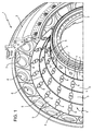
- Figure 1 shows a combustion chamber 1 of a gas turbine (not shown in full).
- the combustion chamber 1 comprises an annular casing 2 extending about an axis and is provided with a heat-insulating coating 3, which internally coats the casing 2 and delimits a combustion volume 4.
- Figure 1 also shows burner housings 6, which are not described for the sake of simplicity.
- the heat-insulating coating 3 comprises a plurality of heat-insulating tiles 5 made of refractory material, arranged in adjacent rows along circumferences around the axis of the combustion chamber 1.
- the heat-insulating coating 3 may also include rows of metallic heat-insulating shields 7, in particular in the less hot portions of the combustion chamber adjacent to the outlet.
- the heat-insulating tiles 5 are fastened to the casing 2 by anchorage devices 8. Each anchorage device 8 engages a respective pair of adjacent heat-insulating tiles 5.
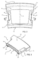
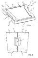
- the heat-insulating tile 5 has a substantially quadrangular shape. More in detail, the heat-insulating tile 5 has a first face or hot face 10 ( Figures 2 and 3 ), exposed to the combustion volume 4, and a second face or cold face 11 ( Figures 3 and 4 ) opposite to the hot face 10 and oriented towards the casing 2.
- the hot face 10 and the cold face 11 may be slightly curved, respectively concave and convex, according to the distance from the axis of the combustion chamber 1.
- the heat-insulating tile 5 also has a first side 12 arranged upstream with respect to a gas flow direction in the combustion chamber 1 and a second side 13 arranged downstream with respect to the first side 12. Sides 15 extend between the hot face 10 and the cold face 11 and between the first side 12 and the second side 13.
- the sides 15 are slightly converging from the first side 12 to the second side 13, so that the heat-insulating tiles 5 in the same row internally and externally define substantially truncated-conical surfaces.
- the heat-insulating tile 5 is substantially symmetrical with respect to a middle longitudinal axis A ( Figure 2 ), longitudinal being here understood to indicate the direction that perpendicularly goes from the first side 12 to the second side 13.
- the heat-insulating tile 5 ( Figures 2-4 ) has an anchorage seat 17 on each side 15 for its coupling with respective anchorage devices 8.
- the anchorage seats 17 are defined by respective recesses, open on the hot face 10 and on the respective side 15.
- the anchorage seats 17 are delimited at the bottom by the coupling surfaces 18 sloping with respect to the hot face 10 of the heat-insulating tile 5.
- the coupling surfaces 18 are substantially flat and sloping from the hot face 10 to the respective side 15 with a constant inclination comprised e.g. between 30° and 60° with respect to the hot face 10.
- the sides 15 have recesses at the respective anchorage seats 17, so that two contiguous tiles in the same row define between them a gap 20 open at the bottom and allowing the passage of a respective anchorage device 8 (in this regard see Figure 5 ). Because of the slope and of the recesses, the coupling surfaces 18 intercept the respective sides 15 at an intermediate height between the hot face 10 and the cold face 11 ( Figure 3 ).
- the cold face 11 of the heat-insulating tile 5 has a recessed portion 21, which is surrounded by a raised portion 22 along the perimeter of the heat-insulating tile 5.
- An insulating layer 25, for example made of woven heat-insulating fibres, is shaped to correspond to the raised portion 22 of the cold face 11 and is applied on it by glue points (not shown).
- the contact surface between the heat-insulating tile 5 and the casing 2 of the combustion chamber 1 is limited to the insulating layer 25 along the raised portion 22, while the recessed portion 21 is separated from the casing 2.
- the material forming the insulating layer 25 also dampens the transmission of mechanical vibration from the casing 2 to the heat-insulating tiles 5.
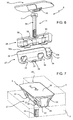
- Figures 6 and 7 show in detail one of the anchorage devices 8, which are structurally identical and may possibly include some size differences to allow the coupling to heat-insulating tiles 5 of different rows.
- the anchorage devices 8 of a same row of heat-insulating tiles 5 are identical.
- Figure 7 shows with dashed lines also portions of a heat-insulating tile 5 coupled to the anchorage device 8 and of the casing 2 of the combustion chamber 1.
- the anchorage device 8 comprises an assembly member 27, a clamping bracket 28, a heat shield member 30 and a screw 31.
- the assembly member 27 comprises a metal sheet folded so as to define a pair of diverging side walls 32, coupled by a bottom portion 33.
- the assembly member 27 is elastically deformable to dampen the vibrations transmitted by the heat-insulating tiles 5.
- the side walls 32 slope to mate with the coupling surfaces 18 of the heat-insulating tiles 5 and define between them a pocket 34. For example, the side walls 32 form between them an angle ⁇ comprised between 60° and 120°.
- the assembly member 27 is shaped so as to be housed in the gap 20 between two adjacent heat-insulating tiles 5.
- the bottom portion 33 of the assembly member 27 has openings 35 to allow the supply of cooling air to the clamping bracket 28 and an opening 36 for housing the through screw 31.
- the clamping bracket 28 is defined by a metal bar inserted into the pocket 34 between the side walls 32 of the assembly member 27.
- the width of the bracket member 28 is such that the bracket member 28 comes first in contact with the bottom portion 33 of the assembly member 27 and then with the side walls 32.
- the clamping bracket 28 has through holes 38 in positions corresponding to the openings 35 of the bottom portion of the assembly member 27. Furthermore, a through seat 39 allows the insertion of the screw 31 through the clamping bracket 28 and the opening 36 in the assembly member 27. The clamping force exerted by the screw 31 is transmitted and distributed by the clamping bracket 28 to the assembly member 27, which is then stably held in its seat. The clamping bracket 28, furthermore, exerts pressure on the bottom portion 33 of the assembly member 27, thus transmitting through the side walls 32 a desired force against the coupling surfaces 18 of the anchorage seats 17 of heat-insulating tiles 5.
- the heat shield member 30 comprises a plate of a metal alloy resistant to high temperatures, possibly covered with a heat-insulating layer (not shown in detail) made of refractory material, for example a ceramic material.
- the heat shield member 30 covers the assembly member 27 and the clamping bracket 28.
- the clamping bracket 28 is then trapped in the pocket 34 between the assembly member 27 and the heat shield member 30.
- the heat shield member 30 extends beyond the edges of the side walls 32 and, in particular, is shaped so as to close the gap 20 housing the anchorage device 8.
- the heat shield member 30 thus forms a substantially continuous surface with the hot faces 10 of adjacent heat-insulating tiles 5, protecting the assembly member 27 and the clamping bracket 28.
- the heat shield member 30 On the side facing the clamping bracket 28, the heat shield member 30 has a seat 40 to house the head 41 of the screw 31.
- the walls defining the seat 40 are also shaped so as to press the clamping bracket 28 against the bottom wall 33 of the assembly member 27 thanks to the tightening of the screw 31.
- the screw 31 is coupled to a seat (not shown) in the casing 2.
- the air possibly required for cooling the heat shield member 30 may be fed through the openings 35 of the assembly member 27 and the through holes 38 in the clamping bracket 28.
- the screw 31, which has an axial through channel 42 for cooling, can be reached with a tool through a hole 43 in the heat shield member 30.
- the described heat-insulating tile 5 advantageously has a reduced thickness if compared to conventional ceramic tiles.
- the tile is just as thick as necessary to obtain an effective coupling with the anchorage devices 8, thanks to the shape of the anchorage seats 17, whose sloping coupling surfaces 18 extend to the hot face 10.
- the reduced thickness allows using the heat-insulating tile 5 in substitution of metal shields in the combustion chambers of medium-small sized gas turbines.
- the heat-insulating tile 5 does not require any cooling air, which may only be possibly required for the anchorage devices 8. The air tapping from the compressor is then dramatically reduced, to the advantage of the efficiency of the machine.
- the coupling between the mating sloping surfaces 18 and the elastic side walls 32 of the assembly member 27 of the anchorage device 8 is advantageous because the coupling forces are distributed over a wide area, thus reducing the punctual stresses, particularly close to the chamfered edges.
- Some advantages deriving from the anchorage device 8 are related to the fact that the required cooling air flow rate is limited and comparable with the flow rate required by the known anchorages of the not flame-exposed type, but, at the same time, without the limitations that such anchorages impose on a minimum thickness of the heat-insulating tiles.
- the known flame-exposed anchorages that have less stringent limitations on a minimum thickness, require significant amounts of cooling air, thus having an impact on the overall efficiency of the machine.
- the anchorage devices 8 can be frontally coupled and removed with respect to the casing 2 of the combustion chamber 1, thus facilitating the maintenance operations. Moreover, the installation of heat-insulating tiles by the anchorage devices 8 requires only the drilling of the casing 2 for machining the coupling seats (directly or by means of interface plates) of the screws 31. No thinning processing is required which could jeopardise the structural integrity of the combustion chamber 1.
Landscapes
- Engineering & Computer Science (AREA)
- Chemical & Material Sciences (AREA)
- Combustion & Propulsion (AREA)
- Mechanical Engineering (AREA)
- General Engineering & Computer Science (AREA)
- Turbine Rotor Nozzle Sealing (AREA)
- Furnace Housings, Linings, Walls, And Ceilings (AREA)
Applications Claiming Priority (1)
| Application Number | Priority Date | Filing Date | Title |
|---|---|---|---|
| ITUB20151339 | 2015-06-08 |
Publications (2)
| Publication Number | Publication Date |
|---|---|
| EP3104079A1 true EP3104079A1 (fr) | 2016-12-14 |
| EP3104079B1 EP3104079B1 (fr) | 2018-10-31 |
Family
ID=54150587
Family Applications (1)
| Application Number | Title | Priority Date | Filing Date |
|---|---|---|---|
| EP16173610.3A Active EP3104079B1 (fr) | 2015-06-08 | 2016-06-08 | Chambres de combustion de turbines à gaz ayant un dispositif d'ancrage de boucliers thermiques |
Country Status (2)
| Country | Link |
|---|---|
| EP (1) | EP3104079B1 (fr) |
| CN (1) | CN106247400B (fr) |
Cited By (3)
| Publication number | Priority date | Publication date | Assignee | Title |
|---|---|---|---|---|
| EP3640544A1 (fr) * | 2018-10-15 | 2020-04-22 | United Technologies Corporation | Ensemble de fixation de chemise de chambre de combustion pour moteur à turbine à gaz |
| US11255547B2 (en) | 2018-10-15 | 2022-02-22 | Raytheon Technologies Corporation | Combustor liner attachment assembly for gas turbine engine |
| US11530817B2 (en) | 2018-12-12 | 2022-12-20 | Rolls-Royce Plc | Combustor, a tile holder and a tile |
Families Citing this family (1)
| Publication number | Priority date | Publication date | Assignee | Title |
|---|---|---|---|---|
| CN116906936B (zh) * | 2023-06-08 | 2025-11-21 | 上海电气燃气轮机有限公司 | 一种燃烧室瓦块的固定机构、以及燃烧室热屏装置 |
Citations (4)
| Publication number | Priority date | Publication date | Assignee | Title |
|---|---|---|---|---|
| US2548485A (en) * | 1946-01-09 | 1951-04-10 | Shell Dev | Combustion chamber lining |
| US20010035003A1 (en) * | 2000-03-31 | 2001-11-01 | Quiet Systems International, Llc | Passive mounted lining system |
| US20040118124A1 (en) * | 2002-12-19 | 2004-06-24 | Peter Tiemann | Flow control body |
| WO2005019731A1 (fr) * | 2003-08-13 | 2005-03-03 | Siemens Aktiengesellschaft | Chambre de combustion, notamment chambre de combustion pour turbine a gaz |
Family Cites Families (6)
| Publication number | Priority date | Publication date | Assignee | Title |
|---|---|---|---|---|
| JPS5941716A (ja) * | 1982-08-31 | 1984-03-08 | Agency Of Ind Science & Technol | セラミツク耐火壁構造の燃焼器 |
| DE3625056C2 (de) * | 1986-07-24 | 1997-05-28 | Siemens Ag | Feuerfeste Auskleidung, insbesondere für Brennkammern von Gasturbinenanlagen |
| JPS63201426A (ja) * | 1987-02-14 | 1988-08-19 | Toshiba Corp | 燃焼器ライナ−における熱遮断用セラミツクスブロツクの支持装置 |
| DE19502730A1 (de) * | 1995-01-28 | 1996-08-01 | Abb Management Ag | Keramische Auskleidung |
| CN2508118Y (zh) * | 2001-11-28 | 2002-08-28 | 吴亦安 | 拱桥式耐磨刚玉陶瓷内衬锅炉燃烧器筒体 |
| CN103557536B (zh) * | 2013-11-14 | 2016-01-06 | 深圳智慧能源技术有限公司 | 陶瓷热屏蔽片及耐热结构 |
-
2016
- 2016-06-08 EP EP16173610.3A patent/EP3104079B1/fr active Active
- 2016-06-08 CN CN201610404520.8A patent/CN106247400B/zh active Active
Patent Citations (4)
| Publication number | Priority date | Publication date | Assignee | Title |
|---|---|---|---|---|
| US2548485A (en) * | 1946-01-09 | 1951-04-10 | Shell Dev | Combustion chamber lining |
| US20010035003A1 (en) * | 2000-03-31 | 2001-11-01 | Quiet Systems International, Llc | Passive mounted lining system |
| US20040118124A1 (en) * | 2002-12-19 | 2004-06-24 | Peter Tiemann | Flow control body |
| WO2005019731A1 (fr) * | 2003-08-13 | 2005-03-03 | Siemens Aktiengesellschaft | Chambre de combustion, notamment chambre de combustion pour turbine a gaz |
Cited By (4)
| Publication number | Priority date | Publication date | Assignee | Title |
|---|---|---|---|---|
| EP3640544A1 (fr) * | 2018-10-15 | 2020-04-22 | United Technologies Corporation | Ensemble de fixation de chemise de chambre de combustion pour moteur à turbine à gaz |
| US11255547B2 (en) | 2018-10-15 | 2022-02-22 | Raytheon Technologies Corporation | Combustor liner attachment assembly for gas turbine engine |
| US11293637B2 (en) * | 2018-10-15 | 2022-04-05 | Raytheon Technologies Corporation | Combustor liner attachment assembly for gas turbine engine |
| US11530817B2 (en) | 2018-12-12 | 2022-12-20 | Rolls-Royce Plc | Combustor, a tile holder and a tile |
Also Published As
| Publication number | Publication date |
|---|---|
| CN106247400B (zh) | 2020-01-31 |
| EP3104079B1 (fr) | 2018-10-31 |
| CN106247400A (zh) | 2016-12-21 |
Similar Documents
| Publication | Publication Date | Title |
|---|---|---|
| EP3104079B1 (fr) | Chambres de combustion de turbines à gaz ayant un dispositif d'ancrage de boucliers thermiques | |
| EP2514925B1 (fr) | Système de fixation d'une virole compostie à matrice céramique | |
| US7779637B2 (en) | Heat shield | |
| EP2188497B1 (fr) | Configuration perfectionnée de joints pour liquide de refroidissement pour segments annulaires | |
| US9869201B2 (en) | Impingement cooled spline seal | |
| RU2589890C2 (ru) | Газовая турбина (варианты) и опорное устройство жаровой трубы | |
| DK2326879T3 (en) | Rear vented refractory wall, especially for an incinerator | |
| JP2002506963A (ja) | 燃焼器用壁セグメントおよび燃焼器 | |
| US9382846B2 (en) | Sealing element for sealing a gap | |
| RU2184319C2 (ru) | Теплозащитный экран, в частности для конструкционных элементов газотурбинных установок | |
| CN104769362B (zh) | 用于保持隔热屏块的保持元件和用于冷却隔热屏的支承结构的方法 | |
| EP3104077B1 (fr) | Carreau céramique thermo-isolant présentant une faible épaisseur pour une chambre de combustion d'une turbine à gaz | |
| US5800773A (en) | Segmented smelt spout | |
| EP3022488B1 (fr) | Ensemble de tête pour un brûleur rayonnant | |
| US20080127652A1 (en) | Heat Shield Element | |
| US20100146985A1 (en) | High Temperature-Resistant Sealing Assembly, Especially for Gas Turbines | |
| US20210190319A1 (en) | Tubular combustion chamber with ceramic cladding | |
| WO2008110484A3 (fr) | Canal pour gaz très chaud et système de division de canal | |
| EP4206532B1 (fr) | Chambre de combustion pour une turbine à gaz | |
| CN107101224A (zh) | 一种单管燃烧室和燃气轮机 | |
| CN106164590B (zh) | 燃气轮机组件的燃烧室和用于燃气轮机组件的燃烧室的绝热砖的支撑构件 | |
| US7322196B2 (en) | Combustion chamber for combusting a combustible fluid mixture | |
| EP3623703B1 (fr) | Tuile thermo-isolante métallique pour la chambre de combustion d'une turbine à gaz | |
| CN113390266A (zh) | 一种用于熔融还原炉过渡区的冷却装置 | |
| US11821629B2 (en) | Combustion chamber |
Legal Events
| Date | Code | Title | Description |
|---|---|---|---|
| PUAI | Public reference made under article 153(3) epc to a published international application that has entered the european phase |
Free format text: ORIGINAL CODE: 0009012 |
|
| STAA | Information on the status of an ep patent application or granted ep patent |
Free format text: STATUS: THE APPLICATION HAS BEEN PUBLISHED |
|
| AK | Designated contracting states |
Kind code of ref document: A1 Designated state(s): AL AT BE BG CH CY CZ DE DK EE ES FI FR GB GR HR HU IE IS IT LI LT LU LV MC MK MT NL NO PL PT RO RS SE SI SK SM TR |
|
| AX | Request for extension of the european patent |
Extension state: BA ME |
|
| STAA | Information on the status of an ep patent application or granted ep patent |
Free format text: STATUS: REQUEST FOR EXAMINATION WAS MADE |
|
| 17P | Request for examination filed |
Effective date: 20170614 |
|
| RBV | Designated contracting states (corrected) |
Designated state(s): AL AT BE BG CH CY CZ DE DK EE ES FI FR GB GR HR HU IE IS IT LI LT LU LV MC MK MT NL NO PL PT RO RS SE SI SK SM TR |
|
| STAA | Information on the status of an ep patent application or granted ep patent |
Free format text: STATUS: EXAMINATION IS IN PROGRESS |
|
| 17Q | First examination report despatched |
Effective date: 20171025 |
|
| GRAP | Despatch of communication of intention to grant a patent |
Free format text: ORIGINAL CODE: EPIDOSNIGR1 |
|
| STAA | Information on the status of an ep patent application or granted ep patent |
Free format text: STATUS: GRANT OF PATENT IS INTENDED |
|
| INTG | Intention to grant announced |
Effective date: 20180509 |
|
| RAP1 | Party data changed (applicant data changed or rights of an application transferred) |
Owner name: ANSALDO ENERGIA S.P.A. |
|
| GRAS | Grant fee paid |
Free format text: ORIGINAL CODE: EPIDOSNIGR3 |
|
| GRAA | (expected) grant |
Free format text: ORIGINAL CODE: 0009210 |
|
| STAA | Information on the status of an ep patent application or granted ep patent |
Free format text: STATUS: THE PATENT HAS BEEN GRANTED |
|
| AK | Designated contracting states |
Kind code of ref document: B1 Designated state(s): AL AT BE BG CH CY CZ DE DK EE ES FI FR GB GR HR HU IE IS IT LI LT LU LV MC MK MT NL NO PL PT RO RS SE SI SK SM TR |
|
| REG | Reference to a national code |
Ref country code: CH Ref legal event code: EP Ref country code: GB Ref legal event code: FG4D |
|
| REG | Reference to a national code |
Ref country code: AT Ref legal event code: REF Ref document number: 1059850 Country of ref document: AT Kind code of ref document: T Effective date: 20181115 |
|
| REG | Reference to a national code |
Ref country code: DE Ref legal event code: R096 Ref document number: 602016006727 Country of ref document: DE |
|
| REG | Reference to a national code |
Ref country code: IE Ref legal event code: FG4D |
|
| REG | Reference to a national code |
Ref country code: NL Ref legal event code: MP Effective date: 20181031 |
|
| REG | Reference to a national code |
Ref country code: LT Ref legal event code: MG4D |
|
| REG | Reference to a national code |
Ref country code: AT Ref legal event code: MK05 Ref document number: 1059850 Country of ref document: AT Kind code of ref document: T Effective date: 20181031 |
|
| PG25 | Lapsed in a contracting state [announced via postgrant information from national office to epo] |
Ref country code: PL Free format text: LAPSE BECAUSE OF FAILURE TO SUBMIT A TRANSLATION OF THE DESCRIPTION OR TO PAY THE FEE WITHIN THE PRESCRIBED TIME-LIMIT Effective date: 20181031 Ref country code: HR Free format text: LAPSE BECAUSE OF FAILURE TO SUBMIT A TRANSLATION OF THE DESCRIPTION OR TO PAY THE FEE WITHIN THE PRESCRIBED TIME-LIMIT Effective date: 20181031 Ref country code: LT Free format text: LAPSE BECAUSE OF FAILURE TO SUBMIT A TRANSLATION OF THE DESCRIPTION OR TO PAY THE FEE WITHIN THE PRESCRIBED TIME-LIMIT Effective date: 20181031 Ref country code: AT Free format text: LAPSE BECAUSE OF FAILURE TO SUBMIT A TRANSLATION OF THE DESCRIPTION OR TO PAY THE FEE WITHIN THE PRESCRIBED TIME-LIMIT Effective date: 20181031 Ref country code: BG Free format text: LAPSE BECAUSE OF FAILURE TO SUBMIT A TRANSLATION OF THE DESCRIPTION OR TO PAY THE FEE WITHIN THE PRESCRIBED TIME-LIMIT Effective date: 20190131 Ref country code: IS Free format text: LAPSE BECAUSE OF FAILURE TO SUBMIT A TRANSLATION OF THE DESCRIPTION OR TO PAY THE FEE WITHIN THE PRESCRIBED TIME-LIMIT Effective date: 20190228 Ref country code: ES Free format text: LAPSE BECAUSE OF FAILURE TO SUBMIT A TRANSLATION OF THE DESCRIPTION OR TO PAY THE FEE WITHIN THE PRESCRIBED TIME-LIMIT Effective date: 20181031 Ref country code: NO Free format text: LAPSE BECAUSE OF FAILURE TO SUBMIT A TRANSLATION OF THE DESCRIPTION OR TO PAY THE FEE WITHIN THE PRESCRIBED TIME-LIMIT Effective date: 20190131 Ref country code: FI Free format text: LAPSE BECAUSE OF FAILURE TO SUBMIT A TRANSLATION OF THE DESCRIPTION OR TO PAY THE FEE WITHIN THE PRESCRIBED TIME-LIMIT Effective date: 20181031 Ref country code: LV Free format text: LAPSE BECAUSE OF FAILURE TO SUBMIT A TRANSLATION OF THE DESCRIPTION OR TO PAY THE FEE WITHIN THE PRESCRIBED TIME-LIMIT Effective date: 20181031 |
|
| PG25 | Lapsed in a contracting state [announced via postgrant information from national office to epo] |
Ref country code: RS Free format text: LAPSE BECAUSE OF FAILURE TO SUBMIT A TRANSLATION OF THE DESCRIPTION OR TO PAY THE FEE WITHIN THE PRESCRIBED TIME-LIMIT Effective date: 20181031 Ref country code: AL Free format text: LAPSE BECAUSE OF FAILURE TO SUBMIT A TRANSLATION OF THE DESCRIPTION OR TO PAY THE FEE WITHIN THE PRESCRIBED TIME-LIMIT Effective date: 20181031 Ref country code: GR Free format text: LAPSE BECAUSE OF FAILURE TO SUBMIT A TRANSLATION OF THE DESCRIPTION OR TO PAY THE FEE WITHIN THE PRESCRIBED TIME-LIMIT Effective date: 20190201 Ref country code: SE Free format text: LAPSE BECAUSE OF FAILURE TO SUBMIT A TRANSLATION OF THE DESCRIPTION OR TO PAY THE FEE WITHIN THE PRESCRIBED TIME-LIMIT Effective date: 20181031 Ref country code: PT Free format text: LAPSE BECAUSE OF FAILURE TO SUBMIT A TRANSLATION OF THE DESCRIPTION OR TO PAY THE FEE WITHIN THE PRESCRIBED TIME-LIMIT Effective date: 20190301 Ref country code: NL Free format text: LAPSE BECAUSE OF FAILURE TO SUBMIT A TRANSLATION OF THE DESCRIPTION OR TO PAY THE FEE WITHIN THE PRESCRIBED TIME-LIMIT Effective date: 20181031 |
|
| PG25 | Lapsed in a contracting state [announced via postgrant information from national office to epo] |
Ref country code: DK Free format text: LAPSE BECAUSE OF FAILURE TO SUBMIT A TRANSLATION OF THE DESCRIPTION OR TO PAY THE FEE WITHIN THE PRESCRIBED TIME-LIMIT Effective date: 20181031 Ref country code: IT Free format text: LAPSE BECAUSE OF FAILURE TO SUBMIT A TRANSLATION OF THE DESCRIPTION OR TO PAY THE FEE WITHIN THE PRESCRIBED TIME-LIMIT Effective date: 20181031 Ref country code: CZ Free format text: LAPSE BECAUSE OF FAILURE TO SUBMIT A TRANSLATION OF THE DESCRIPTION OR TO PAY THE FEE WITHIN THE PRESCRIBED TIME-LIMIT Effective date: 20181031 |
|
| REG | Reference to a national code |
Ref country code: DE Ref legal event code: R097 Ref document number: 602016006727 Country of ref document: DE |
|
| PG25 | Lapsed in a contracting state [announced via postgrant information from national office to epo] |
Ref country code: RO Free format text: LAPSE BECAUSE OF FAILURE TO SUBMIT A TRANSLATION OF THE DESCRIPTION OR TO PAY THE FEE WITHIN THE PRESCRIBED TIME-LIMIT Effective date: 20181031 Ref country code: EE Free format text: LAPSE BECAUSE OF FAILURE TO SUBMIT A TRANSLATION OF THE DESCRIPTION OR TO PAY THE FEE WITHIN THE PRESCRIBED TIME-LIMIT Effective date: 20181031 Ref country code: SM Free format text: LAPSE BECAUSE OF FAILURE TO SUBMIT A TRANSLATION OF THE DESCRIPTION OR TO PAY THE FEE WITHIN THE PRESCRIBED TIME-LIMIT Effective date: 20181031 Ref country code: SK Free format text: LAPSE BECAUSE OF FAILURE TO SUBMIT A TRANSLATION OF THE DESCRIPTION OR TO PAY THE FEE WITHIN THE PRESCRIBED TIME-LIMIT Effective date: 20181031 |
|
| PLBE | No opposition filed within time limit |
Free format text: ORIGINAL CODE: 0009261 |
|
| STAA | Information on the status of an ep patent application or granted ep patent |
Free format text: STATUS: NO OPPOSITION FILED WITHIN TIME LIMIT |
|
| 26N | No opposition filed |
Effective date: 20190801 |
|
| PG25 | Lapsed in a contracting state [announced via postgrant information from national office to epo] |
Ref country code: SI Free format text: LAPSE BECAUSE OF FAILURE TO SUBMIT A TRANSLATION OF THE DESCRIPTION OR TO PAY THE FEE WITHIN THE PRESCRIBED TIME-LIMIT Effective date: 20181031 |
|
| PG25 | Lapsed in a contracting state [announced via postgrant information from national office to epo] |
Ref country code: MC Free format text: LAPSE BECAUSE OF FAILURE TO SUBMIT A TRANSLATION OF THE DESCRIPTION OR TO PAY THE FEE WITHIN THE PRESCRIBED TIME-LIMIT Effective date: 20181031 |
|
| REG | Reference to a national code |
Ref country code: CH Ref legal event code: PL |
|
| REG | Reference to a national code |
Ref country code: BE Ref legal event code: MM Effective date: 20190630 |
|
| PG25 | Lapsed in a contracting state [announced via postgrant information from national office to epo] |
Ref country code: TR Free format text: LAPSE BECAUSE OF FAILURE TO SUBMIT A TRANSLATION OF THE DESCRIPTION OR TO PAY THE FEE WITHIN THE PRESCRIBED TIME-LIMIT Effective date: 20181031 |
|
| PG25 | Lapsed in a contracting state [announced via postgrant information from national office to epo] |
Ref country code: IE Free format text: LAPSE BECAUSE OF NON-PAYMENT OF DUE FEES Effective date: 20190608 |
|
| PG25 | Lapsed in a contracting state [announced via postgrant information from national office to epo] |
Ref country code: BE Free format text: LAPSE BECAUSE OF NON-PAYMENT OF DUE FEES Effective date: 20190630 Ref country code: LU Free format text: LAPSE BECAUSE OF NON-PAYMENT OF DUE FEES Effective date: 20190608 Ref country code: CH Free format text: LAPSE BECAUSE OF NON-PAYMENT OF DUE FEES Effective date: 20190630 Ref country code: LI Free format text: LAPSE BECAUSE OF NON-PAYMENT OF DUE FEES Effective date: 20190630 |
|
| PG25 | Lapsed in a contracting state [announced via postgrant information from national office to epo] |
Ref country code: FR Free format text: LAPSE BECAUSE OF NON-PAYMENT OF DUE FEES Effective date: 20190630 |
|
| GBPC | Gb: european patent ceased through non-payment of renewal fee |
Effective date: 20200608 |
|
| PG25 | Lapsed in a contracting state [announced via postgrant information from national office to epo] |
Ref country code: GB Free format text: LAPSE BECAUSE OF NON-PAYMENT OF DUE FEES Effective date: 20200608 |
|
| PG25 | Lapsed in a contracting state [announced via postgrant information from national office to epo] |
Ref country code: CY Free format text: LAPSE BECAUSE OF FAILURE TO SUBMIT A TRANSLATION OF THE DESCRIPTION OR TO PAY THE FEE WITHIN THE PRESCRIBED TIME-LIMIT Effective date: 20181031 |
|
| PG25 | Lapsed in a contracting state [announced via postgrant information from national office to epo] |
Ref country code: HU Free format text: LAPSE BECAUSE OF FAILURE TO SUBMIT A TRANSLATION OF THE DESCRIPTION OR TO PAY THE FEE WITHIN THE PRESCRIBED TIME-LIMIT; INVALID AB INITIO Effective date: 20160608 Ref country code: MT Free format text: LAPSE BECAUSE OF FAILURE TO SUBMIT A TRANSLATION OF THE DESCRIPTION OR TO PAY THE FEE WITHIN THE PRESCRIBED TIME-LIMIT Effective date: 20181031 |
|
| PG25 | Lapsed in a contracting state [announced via postgrant information from national office to epo] |
Ref country code: MK Free format text: LAPSE BECAUSE OF FAILURE TO SUBMIT A TRANSLATION OF THE DESCRIPTION OR TO PAY THE FEE WITHIN THE PRESCRIBED TIME-LIMIT Effective date: 20181031 |
|
| P01 | Opt-out of the competence of the unified patent court (upc) registered |
Effective date: 20240430 |
|
| PGFP | Annual fee paid to national office [announced via postgrant information from national office to epo] |
Ref country code: DE Payment date: 20250618 Year of fee payment: 10 |