EP3104108A1 - Chemische wärmespeichervorrichtung - Google Patents
Chemische wärmespeichervorrichtung Download PDFInfo
- Publication number
- EP3104108A1 EP3104108A1 EP15745868.8A EP15745868A EP3104108A1 EP 3104108 A1 EP3104108 A1 EP 3104108A1 EP 15745868 A EP15745868 A EP 15745868A EP 3104108 A1 EP3104108 A1 EP 3104108A1
- Authority
- EP
- European Patent Office
- Prior art keywords
- valve
- adsorber
- reactor
- thermal storage
- storage device
- Prior art date
- Legal status (The legal status is an assumption and is not a legal conclusion. Google has not performed a legal analysis and makes no representation as to the accuracy of the status listed.)
- Withdrawn
Links
Images






Classifications
-
- F—MECHANICAL ENGINEERING; LIGHTING; HEATING; WEAPONS; BLASTING
- F28—HEAT EXCHANGE IN GENERAL
- F28D—HEAT-EXCHANGE APPARATUS, NOT PROVIDED FOR IN ANOTHER SUBCLASS, IN WHICH THE HEAT-EXCHANGE MEDIA DO NOT COME INTO DIRECT CONTACT
- F28D20/00—Heat storage plants or apparatus in general; Regenerative heat-exchange apparatus not covered by groups F28D17/00 or F28D19/00
- F28D20/003—Heat storage plants or apparatus in general; Regenerative heat-exchange apparatus not covered by groups F28D17/00 or F28D19/00 using thermochemical reactions
-
- F—MECHANICAL ENGINEERING; LIGHTING; HEATING; WEAPONS; BLASTING
- F01—MACHINES OR ENGINES IN GENERAL; ENGINE PLANTS IN GENERAL; STEAM ENGINES
- F01N—GAS-FLOW SILENCERS OR EXHAUST APPARATUS FOR MACHINES OR ENGINES IN GENERAL; GAS-FLOW SILENCERS OR EXHAUST APPARATUS FOR INTERNAL-COMBUSTION ENGINES
- F01N13/00—Exhaust or silencing apparatus characterised by constructional features
- F01N13/009—Exhaust or silencing apparatus characterised by constructional features having two or more separate purifying devices arranged in series
-
- F—MECHANICAL ENGINEERING; LIGHTING; HEATING; WEAPONS; BLASTING
- F01—MACHINES OR ENGINES IN GENERAL; ENGINE PLANTS IN GENERAL; STEAM ENGINES
- F01N—GAS-FLOW SILENCERS OR EXHAUST APPARATUS FOR MACHINES OR ENGINES IN GENERAL; GAS-FLOW SILENCERS OR EXHAUST APPARATUS FOR INTERNAL-COMBUSTION ENGINES
- F01N3/00—Exhaust or silencing apparatus having means for purifying, rendering innocuous, or otherwise treating exhaust
- F01N3/08—Exhaust or silencing apparatus having means for purifying, rendering innocuous, or otherwise treating exhaust for rendering innocuous
- F01N3/10—Exhaust or silencing apparatus having means for purifying, rendering innocuous, or otherwise treating exhaust for rendering innocuous by thermal or catalytic conversion of noxious components of exhaust
-
- F—MECHANICAL ENGINEERING; LIGHTING; HEATING; WEAPONS; BLASTING
- F01—MACHINES OR ENGINES IN GENERAL; ENGINE PLANTS IN GENERAL; STEAM ENGINES
- F01N—GAS-FLOW SILENCERS OR EXHAUST APPARATUS FOR MACHINES OR ENGINES IN GENERAL; GAS-FLOW SILENCERS OR EXHAUST APPARATUS FOR INTERNAL-COMBUSTION ENGINES
- F01N3/00—Exhaust or silencing apparatus having means for purifying, rendering innocuous, or otherwise treating exhaust
- F01N3/08—Exhaust or silencing apparatus having means for purifying, rendering innocuous, or otherwise treating exhaust for rendering innocuous
- F01N3/10—Exhaust or silencing apparatus having means for purifying, rendering innocuous, or otherwise treating exhaust for rendering innocuous by thermal or catalytic conversion of noxious components of exhaust
- F01N3/103—Oxidation catalysts for HC and CO only
-
- F—MECHANICAL ENGINEERING; LIGHTING; HEATING; WEAPONS; BLASTING
- F01—MACHINES OR ENGINES IN GENERAL; ENGINE PLANTS IN GENERAL; STEAM ENGINES
- F01N—GAS-FLOW SILENCERS OR EXHAUST APPARATUS FOR MACHINES OR ENGINES IN GENERAL; GAS-FLOW SILENCERS OR EXHAUST APPARATUS FOR INTERNAL-COMBUSTION ENGINES
- F01N3/00—Exhaust or silencing apparatus having means for purifying, rendering innocuous, or otherwise treating exhaust
- F01N3/08—Exhaust or silencing apparatus having means for purifying, rendering innocuous, or otherwise treating exhaust for rendering innocuous
- F01N3/10—Exhaust or silencing apparatus having means for purifying, rendering innocuous, or otherwise treating exhaust for rendering innocuous by thermal or catalytic conversion of noxious components of exhaust
- F01N3/18—Exhaust or silencing apparatus having means for purifying, rendering innocuous, or otherwise treating exhaust for rendering innocuous by thermal or catalytic conversion of noxious components of exhaust characterised by methods of operation; Control
- F01N3/20—Exhaust or silencing apparatus having means for purifying, rendering innocuous, or otherwise treating exhaust for rendering innocuous by thermal or catalytic conversion of noxious components of exhaust characterised by methods of operation; Control specially adapted for catalytic conversion
- F01N3/2006—Periodically heating or cooling catalytic reactors, e.g. at cold starting or overheating
-
- F—MECHANICAL ENGINEERING; LIGHTING; HEATING; WEAPONS; BLASTING
- F01—MACHINES OR ENGINES IN GENERAL; ENGINE PLANTS IN GENERAL; STEAM ENGINES
- F01N—GAS-FLOW SILENCERS OR EXHAUST APPARATUS FOR MACHINES OR ENGINES IN GENERAL; GAS-FLOW SILENCERS OR EXHAUST APPARATUS FOR INTERNAL-COMBUSTION ENGINES
- F01N3/00—Exhaust or silencing apparatus having means for purifying, rendering innocuous, or otherwise treating exhaust
- F01N3/08—Exhaust or silencing apparatus having means for purifying, rendering innocuous, or otherwise treating exhaust for rendering innocuous
- F01N3/10—Exhaust or silencing apparatus having means for purifying, rendering innocuous, or otherwise treating exhaust for rendering innocuous by thermal or catalytic conversion of noxious components of exhaust
- F01N3/18—Exhaust or silencing apparatus having means for purifying, rendering innocuous, or otherwise treating exhaust for rendering innocuous by thermal or catalytic conversion of noxious components of exhaust characterised by methods of operation; Control
- F01N3/20—Exhaust or silencing apparatus having means for purifying, rendering innocuous, or otherwise treating exhaust for rendering innocuous by thermal or catalytic conversion of noxious components of exhaust characterised by methods of operation; Control specially adapted for catalytic conversion
- F01N3/206—Adding periodically or continuously substances to exhaust gases for promoting purification, e.g. catalytic material in liquid form, NOx reducing agents
- F01N3/2066—Selective catalytic reduction [SCR]
-
- F—MECHANICAL ENGINEERING; LIGHTING; HEATING; WEAPONS; BLASTING
- F01—MACHINES OR ENGINES IN GENERAL; ENGINE PLANTS IN GENERAL; STEAM ENGINES
- F01N—GAS-FLOW SILENCERS OR EXHAUST APPARATUS FOR MACHINES OR ENGINES IN GENERAL; GAS-FLOW SILENCERS OR EXHAUST APPARATUS FOR INTERNAL-COMBUSTION ENGINES
- F01N5/00—Exhaust or silencing apparatus combined or associated with devices profiting by exhaust energy
- F01N5/02—Exhaust or silencing apparatus combined or associated with devices profiting by exhaust energy the devices using heat
-
- F—MECHANICAL ENGINEERING; LIGHTING; HEATING; WEAPONS; BLASTING
- F28—HEAT EXCHANGE IN GENERAL
- F28F—DETAILS OF HEAT-EXCHANGE AND HEAT-TRANSFER APPARATUS, OF GENERAL APPLICATION
- F28F27/00—Control arrangements or safety devices specially adapted for heat-exchange or heat-transfer apparatus
-
- F—MECHANICAL ENGINEERING; LIGHTING; HEATING; WEAPONS; BLASTING
- F01—MACHINES OR ENGINES IN GENERAL; ENGINE PLANTS IN GENERAL; STEAM ENGINES
- F01N—GAS-FLOW SILENCERS OR EXHAUST APPARATUS FOR MACHINES OR ENGINES IN GENERAL; GAS-FLOW SILENCERS OR EXHAUST APPARATUS FOR INTERNAL-COMBUSTION ENGINES
- F01N2240/00—Combination or association of two or more different exhaust treating devices, or of at least one such device with an auxiliary device, not covered by indexing codes F01N2230/00 or F01N2250/00, one of the devices being
- F01N2240/02—Combination or association of two or more different exhaust treating devices, or of at least one such device with an auxiliary device, not covered by indexing codes F01N2230/00 or F01N2250/00, one of the devices being a heat exchanger
-
- F—MECHANICAL ENGINEERING; LIGHTING; HEATING; WEAPONS; BLASTING
- F01—MACHINES OR ENGINES IN GENERAL; ENGINE PLANTS IN GENERAL; STEAM ENGINES
- F01N—GAS-FLOW SILENCERS OR EXHAUST APPARATUS FOR MACHINES OR ENGINES IN GENERAL; GAS-FLOW SILENCERS OR EXHAUST APPARATUS FOR INTERNAL-COMBUSTION ENGINES
- F01N2240/00—Combination or association of two or more different exhaust treating devices, or of at least one such device with an auxiliary device, not covered by indexing codes F01N2230/00 or F01N2250/00, one of the devices being
- F01N2240/10—Combination or association of two or more different exhaust treating devices, or of at least one such device with an auxiliary device, not covered by indexing codes F01N2230/00 or F01N2250/00, one of the devices being a heat accumulator
-
- F—MECHANICAL ENGINEERING; LIGHTING; HEATING; WEAPONS; BLASTING
- F01—MACHINES OR ENGINES IN GENERAL; ENGINE PLANTS IN GENERAL; STEAM ENGINES
- F01N—GAS-FLOW SILENCERS OR EXHAUST APPARATUS FOR MACHINES OR ENGINES IN GENERAL; GAS-FLOW SILENCERS OR EXHAUST APPARATUS FOR INTERNAL-COMBUSTION ENGINES
- F01N2240/00—Combination or association of two or more different exhaust treating devices, or of at least one such device with an auxiliary device, not covered by indexing codes F01N2230/00 or F01N2250/00, one of the devices being
- F01N2240/18—Combination or association of two or more different exhaust treating devices, or of at least one such device with an auxiliary device, not covered by indexing codes F01N2230/00 or F01N2250/00, one of the devices being an adsorber or absorber
-
- F—MECHANICAL ENGINEERING; LIGHTING; HEATING; WEAPONS; BLASTING
- F01—MACHINES OR ENGINES IN GENERAL; ENGINE PLANTS IN GENERAL; STEAM ENGINES
- F01N—GAS-FLOW SILENCERS OR EXHAUST APPARATUS FOR MACHINES OR ENGINES IN GENERAL; GAS-FLOW SILENCERS OR EXHAUST APPARATUS FOR INTERNAL-COMBUSTION ENGINES
- F01N2470/00—Structure or shape of exhaust gas passages, pipes or tubes
- F01N2470/24—Concentric tubes or tubes being concentric to housing, e.g. telescopically assembled
-
- F—MECHANICAL ENGINEERING; LIGHTING; HEATING; WEAPONS; BLASTING
- F01—MACHINES OR ENGINES IN GENERAL; ENGINE PLANTS IN GENERAL; STEAM ENGINES
- F01N—GAS-FLOW SILENCERS OR EXHAUST APPARATUS FOR MACHINES OR ENGINES IN GENERAL; GAS-FLOW SILENCERS OR EXHAUST APPARATUS FOR INTERNAL-COMBUSTION ENGINES
- F01N3/00—Exhaust or silencing apparatus having means for purifying, rendering innocuous, or otherwise treating exhaust
- F01N3/02—Exhaust or silencing apparatus having means for purifying, rendering innocuous, or otherwise treating exhaust for cooling, or for removing solid constituents of, exhaust
- F01N3/021—Exhaust or silencing apparatus having means for purifying, rendering innocuous, or otherwise treating exhaust for cooling, or for removing solid constituents of, exhaust by means of filters
-
- Y—GENERAL TAGGING OF NEW TECHNOLOGICAL DEVELOPMENTS; GENERAL TAGGING OF CROSS-SECTIONAL TECHNOLOGIES SPANNING OVER SEVERAL SECTIONS OF THE IPC; TECHNICAL SUBJECTS COVERED BY FORMER USPC CROSS-REFERENCE ART COLLECTIONS [XRACs] AND DIGESTS
- Y02—TECHNOLOGIES OR APPLICATIONS FOR MITIGATION OR ADAPTATION AGAINST CLIMATE CHANGE
- Y02E—REDUCTION OF GREENHOUSE GAS [GHG] EMISSIONS, RELATED TO ENERGY GENERATION, TRANSMISSION OR DISTRIBUTION
- Y02E60/00—Enabling technologies; Technologies with a potential or indirect contribution to GHG emissions mitigation
- Y02E60/14—Thermal energy storage
-
- Y—GENERAL TAGGING OF NEW TECHNOLOGICAL DEVELOPMENTS; GENERAL TAGGING OF CROSS-SECTIONAL TECHNOLOGIES SPANNING OVER SEVERAL SECTIONS OF THE IPC; TECHNICAL SUBJECTS COVERED BY FORMER USPC CROSS-REFERENCE ART COLLECTIONS [XRACs] AND DIGESTS
- Y02—TECHNOLOGIES OR APPLICATIONS FOR MITIGATION OR ADAPTATION AGAINST CLIMATE CHANGE
- Y02T—CLIMATE CHANGE MITIGATION TECHNOLOGIES RELATED TO TRANSPORTATION
- Y02T10/00—Road transport of goods or passengers
- Y02T10/10—Internal combustion engine [ICE] based vehicles
- Y02T10/12—Improving ICE efficiencies
Definitions
- the present invention relates to a chemical thermal storage device which heats a heating object, for example, provided in an exhaust system of an engine or the like.
- a chemical thermal storage device disclosed in Patent Literature 1 includes an ammonia adsorber having an ammonia adsorption material capable of fixation and desorption of ammonia (NH 3 ) as a chemical reaction medium, a chemical thermal storage reactor that is connected to the ammonia adsorber via a pipe and has a chemical thermal storage material that generates heat upon chemical reaction with NH 3 and desorbs NH 3 with excess heat from a heat source, and an opening and closing valve provided on the pipe.
- NH 3 ammonia adsorption material capable of fixation and desorption of ammonia
- NH 3 desorbed from the ammonia adsorption material of the ammonia adsorber is supplied to the chemical thermal storage reactor via the pipe. Then, the chemical thermal storage material generates heat through chemical reaction between NH 3 and the chemical thermal storage material, and the engine elemental components are heated by the heat. After the warming up of the engine, NH 3 is desorbed from the chemical thermal storage material with excess heat of the engine elemental components. Then, this NH 3 is fixed again (recovered) into the ammonia adsorption material via the pipe. After that, the opening and closing valve is closed.
- Patent Literature 1 Japanese Unexamined Patent Application Publication No. 2013-72558
- the chemical thermal storage reactor (hereinafter simply a reactor) becomes in a high temperature state.
- the opening and closing valve is closed in the case where the opening and closing valve is a solenoid valve.
- the inside of the reactor is filled with NH 3 and the inside of the reactor becomes in an abnormal over-pressurized state.
- it is needed to make the rigidity of the reactor sufficiently high, which causes a physical constitution and a weight of the reactor to increase more than needed.
- the pressure in the adsorber varies depending on the outside air temperature. Specifically, when the outside air temperature becomes high, the temperature of the adsorber becomes high and the pressure in the adsorber becomes high.
- the opening and closing valve is closed, since even when the outside air temperature rises and the adsorber becomes in a high temperature state, NH 3 cannot move from the adsorber to the reactor, the inside of the adsorber is filled with NH 3 and the inside of the adsorber becomes in an abnormal over-pressurized state. Accordingly, when designing the adsorber with the variation of the outside air temperature taken into consideration, it is needed to make the rigidity of the adsorber sufficiently high, which causes a physical constitution and a weight of the adsorber to increase more than needed.
- An object of the present invention is to provide a chemical thermal storage device capable of preventing the inside of a reactor or an adsorber from becoming in an abnormal over-pressurized state.
- a chemical thermal storage device which heats a heating object, the device comprising: a reactor having a thermal storage material that generates heat upon chemical reaction with a gaseous reaction medium; an adsorber having an adsorption material that adsorbs the reaction medium; an opening and closing valve that is provided between the reactor and the adsorber, and opens and closes a flow channel between the reactor and the adsorber; and communication part that causes the reactor and the adsorber to communicate with each other when an internal pressure of at least one of the reactor and the adsorber becomes not less than a predetermined value.
- the communication part may also be provided between the reactor and the adsorber, and may also have at least one of a first valve that opens when the internal pressure of the reactor reaches a first valve-opening setting pressure that is preset and a second valve that opens when the internal pressure of the adsorber reaches a second valve-opening setting pressure that is preset.
- a first valve that opens when the internal pressure of the reactor reaches a first valve-opening setting pressure that is preset
- a second valve that opens when the internal pressure of the adsorber reaches a second valve-opening setting pressure that is preset.
- the first valve may also include a check valve function to shut off a flow of the reaction medium from the adsorber to the reactor
- the second valve may also include a check valve function to shut off a flow of the reaction medium from the reactor to the adsorber.
- first valve and the second valve may also be provided between the reactor and the adsorber, and the second valve-opening setting pressure may also be larger than the first valve-opening setting pressure.
- the second valve can be suppressed from opening for the reaction medium to move from the adsorber to the reactor in the normal state where the internal pressure of the adsorber is relatively high.
- any one of the first valve and the second valve may also constitute one unit along with the opening and closing valve.
- the number of valve units to be used can be a minimum requirement, which is advantageous in view of costs.
- the communication part may also further have a bypass passage provided in parallel to the opening and closing valve, and at least one of the first valve and the second valve may also be provided on the bypass passage.
- a bypass passage provided in parallel to the opening and closing valve, and at least one of the first valve and the second valve may also be provided on the bypass passage.
- the communication part may also have detector that detects the internal pressure of at least one of the reactor and the adsorber, and controller that performs control so as to open the opening and closing valve when it is detected by the detector that the internal pressure of at least one of the reactor and the adsorber is not less than the predetermined value.
- the opening and closing valve opens and the reaction medium becomes to move from the reactor to the adsorber.
- the opening and closing valve opens and the reaction medium becomes to move from the adsorber to the reactor.
- the chemical thermal storage device may also further comprise a relief valve that opens when the internal pressure of at least one of the reactor and the adsorber reaches a predetermined relief setting value.
- a relief valve that opens when the internal pressure of at least one of the reactor and the adsorber reaches a predetermined relief setting value.
- the heating object may also be provided in an exhaust system of an engine, and the relief valve may also be provided between the exhaust system and at least one of the reactor and the adsorber.
- the relief valve opens and the reaction medium is to be discharged from at least one of the reactor and the adsorber to the exhaust system.
- the inside of the reactor or the adsorber can be prevented from becoming in an abnormal over-pressurized state. Therefore, it is not needed to make a physical constitution and a weight of the reactor or the adsorber larger than needed in order not to allow the reactor or the adsorber to burst, and costs can be downsized.
- FIG. 1 is a schematic configuration diagram illustrating an exhaust purification system including a first embodiment of the chemical thermal storage device according to the present invention.
- an exhaust purification system 1 is provided in an exhaust system of a diesel engine 2 of a vehicle (hereinafter referred to simply as engine 2), and is a system that purifies harmful substances (environmental pollutants) contained in exhaust gas discharged from the engine 2.
- the exhaust purification system 1 includes a heat exchanger 4, an oxidation catalyst (DOC: Diesel Oxidation Catalyst) 5, a diesel exhaust particulate removal filter (DPF: Diesel Particulate Filter) 6, a selective reduction catalyst (SCR: Selective Catalytic Reduction) 7 and an oxidation catalyst (ASC: Ammonia Slip Catalyst) 8, which are arranged in the middle of an exhaust passage 3 (exhaust system) connected to the engine 2 sequentially from the upstream side toward the downstream side.
- DOC Diesel Oxidation Catalyst
- DPF Diesel Particulate Filter
- SCR Selective Catalytic Reduction
- ASC Ammonia Slip Catalyst
- the heat exchanger 4 is a device that performs transfer of heat between the exhaust gas from the engine 2 and a reactor 11 mentioned later, and forms a honeycomb structure. Notably, the heat exchanger 4 can use a known heat exchange structure, which is not limited to the honeycomb structure.
- the oxidation catalyst 5 is a catalyst that oxidizes HC (hydrocarbon), CO and the like contained in the exhaust gas and purifies the exhaust gas.
- the DPF 6 is a filter that collects and removes particulate matter (PM: Particulate Matter) contained in the exhaust gas.
- the SCR 7 is a catalyst that reduces NO x contained in the exhaust gas with urea or ammonia (NH 3 ) and purifies the exhaust gas.
- the oxidation catalyst 8 is a catalyst that oxidizes NH 3 that has passed through the SCR 7 and flowed to the downstream side of the SCR 7.
- the exhaust purification system 1 includes the chemical thermal storage device 10 of the present embodiment.
- the chemical thermal storage device 10 is a device that heats the heat exchanger 4 without energy by normally storing heat of the exhaust gas (waste heat) and using the waste heat when needed.
- the chemical thermal storage device 10 includes the reactor 11 disposed around the heat exchanger 4 and an adsorber 12 disposed separate from the heat exchanger 4.
- the reactor 11 contains a thermal storage material 13 that generates heat for heating the heat exchanger 4 upon chemical reaction with NH 3 which is a gaseous reaction medium and that desorbs NH 3 upon reception of the waste heat.
- a thermal storage material 13 a material having a constitution which is MX a which is a halide is used.
- M is an alkali earth metal such as Mg, Ca and Sr, or a transition metal such as Cr, Mn, Fe, Co, Ni, Cu and Zn.
- X is a halogen atom such as Cl, Br and I. a is 2 to 3.
- the adsorber 12 contains an adsorption material 14 capable of retention and desorption of NH 3 through physical adsorption.
- adsorption material 14 activated carbon, carbon black, mesoporous carbon, nanocarbon or the like is used.
- NH 3 can be stored by causing the adsorption material 14 to perform physical adsorption of NH 3 .
- the reactor 11 and the adsorber 12 are connected to each other via a main pipe 15.
- a solenoid valve 16 which is an opening and closing valve that opens and closes a flow channel between the reactor 11 and the adsorber 12 is provided.
- the solenoid valve 16 is controlled by a controller (not shown).
- a bypass pipe 17 (bypass passage) is connected to the main pipe 15.
- a mechanical safety valve 18 is provided in parallel to the solenoid valve 16.
- the safety valve 18 is a separate unit from the solenoid valve 16.
- the safety valve 18 is a valve (first valve) that mechanically opens when the pressure in the reactor 11 reaches a valve-opening setting pressure (first valve-opening setting pressure).
- the valve-opening setting pressure is preset with a spring (not shown) provided in the safety valve 18.
- the safety valve 18 has a check valve function to shut off a flow of NH 3 from the adsorber 12 to the reactor 11. Accordingly, although when the pressure in the reactor 11 reaches the valve-opening setting pressure, NH 3 moves from the reactor 11 to the adsorber 12 by the safety valve 18 opening, even when the pressure in the adsorber 12 reaches the valve-opening setting pressure, NH 3 does not move from the adsorber 12 to the reactor 11.
- the safety valve 18 constitutes communication part that causes the reactor 11 and the adsorber 12 to communicate with each other when the internal pressure of at least one of the reactor 11 and the adsorber 12 becomes not less than a predetermined value.
- the inside of the reactor 11 can be prevented from being abnormally over-pressurized. Accordingly, since it is not needed to make the reactor 11 into an unnecessarily tough structure so as not to allow the reactor 11 to burst, a physical constitution and a weight of the reactor 11 can be suppressed from increasing and costs can be downsized.
- FIG. 3 is a schematic configuration diagram illustrating an exhaust purification system including a second embodiment of the chemical thermal storage device according to the present invention.
- the chemical thermal storage device 10 of the present embodiment includes a safety valve unit 20 in place of the safety valve 18 in the aforementioned first embodiment.
- the safety valve unit 20 has a mechanical safety valve 21 (first valve) and a mechanical safety valve 22 (second valve) that is provided in parallel to this safety valve 21.
- the safety valve 21 is a valve (first valve) that mechanically opens when the pressure in the reactor 11 reaches a valve-opening setting pressure for the reactor (first valve-opening setting pressure).
- the valve-opening setting pressure for the reactor is preset with a spring (not shown) provided in the safety valve 21.
- the safety valve 21 has a check valve function to shut off a flow of NH 3 from the adsorber 12 to the reactor 11.
- the safety valve 22 is a valve (second valve) that mechanically opens when the pressure in the adsorber 12 reaches a valve-opening setting pressure for the adsorber (second valve-opening setting pressure).
- the valve-opening setting pressure for the adsorber is preset with a spring (not shown) provided in the safety valve 22.
- the safety valve 22 has a check valve function to shut off a flow of NH 3 from the reactor 11 to the adsorber 12.
- the pressure in the adsorber 12 is higher than the pressure in the reactor 11. Due to this, the valve-opening setting pressure, for the adsorber, of the safety valve 22 is set to be higher than the valve-opening setting pressure, for the reactor, of the safety valve 21.
- the safety valves 21 and 22 constitute communication part that causes the reactor 11 and the adsorber 12 to communicate with each other when the internal pressure of at least one of the reactor 11 and the adsorber 12 becomes not less than a predetermined value.
- valve-opening setting pressure, for the adsorber, of the safety valve 22 is higher than the valve-opening setting pressure, for the reactor, of the safety valve 21. Due to this, even when the pressure in the adsorber 12 becomes high, the safety valve 22 does not immediately open and erroneous movement of NH 3 from the adsorber 12 to the reactor 11 can be suppressed from occurring. Moreover, since the valve-opening setting pressure, for the reactor, of the safety valve 21 is lower than the valve-opening setting pressure, for the adsorber, of the safety valve 22, movement of NH 3 from the reactor 11 to the adsorber 12 is facilitated and recovery of NH 3 can be promoted.
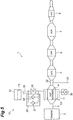
- Figure 5 is a schematic configuration diagram illustrating an exhaust purification system including a third embodiment of the chemical thermal storage device according to the present invention.
- the chemical thermal storage device 10 of the present embodiment includes a relief valve 30 in addition to the aforementioned configuration in the second embodiment.
- the relief valve 30 is provided on a pipe 31 that connects the reactor 11 and the exhaust passage 3.
- One end of the pipe 31 is connected to an exhaust pipe 32 that joins the heat exchanger 4 and the oxidation catalyst 5 on the exhaust passage 3.
- the relief valve 30 is a valve that mechanically opens when the pressure in the reactor 11 reaches a relief setting value.
- the relief setting value is preset with a spring (not shown) provided in the relief valve 30.
- the relief setting value is set to be higher than the valve-opening setting pressure, for the reactor, of the safety valve 21.
- the relief valve 30 has a check valve function to shut off a flow of gas from the exhaust pipe 32 to the reactor 11.
- the release destination of NH 3 is not specially limited to the exhaust pipe 32 but may also be an exhaust pipe in the previous stage of any of the heat exchanger 4, the diesel exhaust particulate removal filter 6, the selective reduction catalyst 7 and the oxidation catalyst 8, or the like.
- the configuration is made to provide the relief valve 30 which opens when the pressure in the reactor 11 reaches the relief setting value between the reactor 11 and the exhaust passage 3
- the configuration may also be made to provide a relief valve that opens when the pressure in the adsorber 12 reaches the relief setting value between the adsorber 12 and the exhaust passage 3, or the configuration may also be made to provide a relief valve that opens when the pressure in the reactor 11 or the adsorber 12 reaches the relief setting value on a passage that joins the reactor 11 and the adsorber 12.
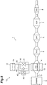
- FIG. 7 is a schematic configuration diagram illustrating an exhaust purification system including a fourth embodiment of the chemical thermal storage device according to the present invention.
- the chemical thermal storage device 10 of the present embodiment includes a solenoid valve unit 40 in place of the solenoid valve 16 and the safety valve 18 in the aforementioned first embodiment.
- the solenoid valve unit 40 includes the check valve 42 with respect to the solenoid valve 41 as an opening and closing valve which is the main part.
- the solenoid valve 41 and the check valve 42 constitute one unit.
- the solenoid valve unit 40 is the solenoid valve 41 equipped with the check valve 42.
- the solenoid valve unit 40 is controlled by a controller (not shown).
- the solenoid valve 41 is a valve that opens and closes the flow channel between the reactor 11 and the adsorber 12.
- the check valve 42 is a valve (first valve) that mechanically opens when the pressure in the reactor 11 reaches a valve-opening setting pressure (first valve-opening setting pressure) and that shuts off a flow of NH 3 from the adsorber 12 to the reactor 11.
- the valve-opening setting pressure is preset with a spring (not shown) provided in the solenoid valve unit 40.
- the check valve 42 constitutes communication part that causes the reactor 11 and the adsorber 12 to communicate with each other when the internal pressure of at least one of the reactor 11 and the adsorber 12 becomes not less than a predetermined value.
- the solenoid valve unit 40 When stopping the engine 2 in recovering NH 3 , the solenoid valve unit 40 closes based on operation of the solenoid valve 41. Then, as illustrated in Figure 8 , the inside of the reactor 11 is filled with high temperature NH 3 gas and the pressure in the reactor 11 steeply rises. In this stage, since when the pressure in the reactor 11 reaches the valve-opening setting pressure of the solenoid valve unit 40, the solenoid valve unit 40 opens based on operation of the check valve 42, NH 3 in the reactor 11 becomes to move to the adsorber 12 through the main pipe 15. In this way, the over-pressurized state in the reactor 11 can be relieved.
- Figure 9 is a schematic configuration diagram illustrating an exhaust purification system including a fifth embodiment of the chemical thermal storage device according to the present invention.
- the chemical thermal storage device 10 of the present embodiment includes a mechanical safety valve 45 in addition to the aforementioned configuration in the fourth embodiment.
- the safety valve 45 is provided on a bypass pipe 46 (bypass passage) connected to the main pipe 15 in parallel to the solenoid valve unit 40.
- the safety valve 45 is a valve (second valve) that mechanically opens when the pressure in the adsorber 12 reaches a valve-opening setting pressure for the adsorber (second valve-opening setting pressure).
- the valve-opening setting pressure for the adsorber is preset with a spring (not shown) provided in the safety valve 45.
- the valve-opening setting pressure, for the adsorber, of the safety valve 45 is set to be higher than the valve-opening setting pressure (first valve-opening setting pressure) of the solenoid valve unit 40.
- the safety valve 45 has a check valve function to shut off a flow of NH 3 from the reactor 11 to the adsorber 12.
- the check valve 42 and the safety valve 45 constitute communication part that causes the reactor 11 and the adsorber 12 to communicate with each other when the internal pressure of at least one of the reactor 11 and the adsorber 12 becomes not less than a predetermined value.
- FIG 11 is a schematic configuration diagram illustrating an exhaust purification system including a sixth embodiment of the chemical thermal storage device according to the present invention.
- the chemical thermal storage device 10 of the present embodiment has the main pipe 15 and the solenoid valve 16 in the aforementioned first embodiment, it does not have the bypass pipe 17 and the safety valve 18 therein.
- the chemical thermal storage device 10 includes a pressure sensor 50 (detector) that detects the pressure in the adsorber 12 and a controller 51 (controller) connected to this pressure sensor 50.
- the controller 51 controls the solenoid valve 16 based on a detection value of the pressure sensor 50.
- Figure 12 is a flowchart illustrating details of solenoid valve control processing procedures executed by the controller 51. The processing is executed during a period except the occasion of the exothermic reaction and the occasion of the regeneration reaction. Notably, the solenoid valve 16 is in the closed state during the period except the occasion of the exothermic reaction and the occasion of the regeneration reaction.
- the detection value of the pressure sensor 50 is inputted (procedure S101) and it is determined whether the pressure, in the adsorber 12, detected by the pressure sensor 50 (adsorber pressure) is lower than a setting pressure (procedure S102).
- the setting pressure is preset based on an experiment or the like.
- control is performed so as to close the solenoid valve 16 (procedure S103), returning to procedure S101.
- control is performed so as to open the solenoid valve 16 (procedure S104), returning to procedure S101.
- the pressure sensor 50 and the controller 51 constitute communication part that causes the reactor 11 and the adsorber 12 to communicate with each other when the internal pressure of at least one of the reactor 11 and the adsorber 12 becomes not less than a predetermined value.
- the solenoid valve 16 is closed during the period except the occasion of the exothermic reaction and the occasion of the regeneration reaction. Due to this, when heat is given to the adsorber 12 due to the outside air temperature rising and the adsorber 12 becomes in a high temperature state, as illustrated in Figure 13 , the pressure in the adsorber 12 steeply rises with high temperature NH 3 gas in the adsorber 12. In this stage, since when the pressure in the adsorber 12 reaches the setting pressure, the solenoid valve 16 opens, NH 3 in the adsorber 12 becomes to move to the reactor 11 through the main pipe 15. In this way, the inside of the adsorber 12 is not abnormally over-pressurized. Accordingly, similarly to the aforementioned second embodiment, since it is not needed to make the rigidity of the adsorber 12 higher than needed, a physical constitution and a weight of the adsorber 12 can be suppressed from increasing.
- control is performed so as to open the solenoid valve 16 when the pressure in the adsorber 12 is not less than the setting pressure
- a pressure sensor that detects the pressure in the reactor 11 may also be provided and control may also be performed so as to open the solenoid valve 16 when the pressure in the reactor 11 becomes not less than the setting pressure.
- the relief valve 30 in the aforementioned third embodiment may also be separately included.
- the present invention is not limited to the aforementioned embodiments.
- any one of the safety valve 18, the safety valve 21 and the check valve 42 each of which is the first valve which mechanically opens when the pressure in the reactor 11 reaches the first valve-opening setting pressure is provided, not providing the first valve which opens when the pressure in the reactor 11 reaches the first valve-opening setting pressure, a configuration to provide the second valve which opens when the pressure in the adsorber 12 reaches the second valve-opening setting pressure may also be employed.
- the second valve-opening setting pressure of the second valve is set to be higher than the first valve-opening setting pressure of the first valve, not specially limited to that mode, the second valve-opening setting pressure of the second valve may also be set equal to the first valve-opening setting pressure of the first valve.
- NH 3 is used as the gaseous reaction medium which undergoes chemical reaction with the thermal storage material 13 in the reactor 11
- CO 2 or the like may also be used.
- examples of the thermal storage material 13 which undergoes chemical reaction with CO 2 include MgO, CaO, BaO, Ca(OH) 2 , Mg(OH) 2 , Fe(OH) 2 , Fe(OH) 3 , FeO, Fe 2 O 3 and Fe 3 O 4 .
- the place where the reactor 11 is disposed may also be, for example, the inside of the heat exchanger 4.
- the adsorber 12 contains the adsorption material 14 which performs physical adsorption of NH 3 , not specially limited to this, the adsorber 12 may also contain an adsorption material that performs chemical adsorption of NH 3 .
- the present invention can also be applied to one which heats another portion (oxidation catalyst 5 or the like) provided in the exhaust system of the diesel engine 2.
- the present invention can also be applied to one which heats a catalyst or the like provided in an exhaust system of a gasoline engine, or one which heats a heating object other than the exhaust system of the engine.
Landscapes
- Engineering & Computer Science (AREA)
- Chemical & Material Sciences (AREA)
- General Engineering & Computer Science (AREA)
- Mechanical Engineering (AREA)
- Chemical Kinetics & Catalysis (AREA)
- Combustion & Propulsion (AREA)
- Health & Medical Sciences (AREA)
- Toxicology (AREA)
- Physics & Mathematics (AREA)
- Thermal Sciences (AREA)
- General Chemical & Material Sciences (AREA)
- Materials Engineering (AREA)
- Exhaust Gas After Treatment (AREA)
Applications Claiming Priority (3)
| Application Number | Priority Date | Filing Date | Title |
|---|---|---|---|
| JP2014020363 | 2014-02-05 | ||
| JP2014098848A JP2015165178A (ja) | 2014-02-05 | 2014-05-12 | 化学蓄熱装置 |
| PCT/JP2015/050953 WO2015118921A1 (ja) | 2014-02-05 | 2015-01-15 | 化学蓄熱装置 |
Publications (2)
| Publication Number | Publication Date |
|---|---|
| EP3104108A1 true EP3104108A1 (de) | 2016-12-14 |
| EP3104108A4 EP3104108A4 (de) | 2017-08-30 |
Family
ID=53777729
Family Applications (1)
| Application Number | Title | Priority Date | Filing Date |
|---|---|---|---|
| EP15745868.8A Withdrawn EP3104108A4 (de) | 2014-02-05 | 2015-01-15 | Chemische wärmespeichervorrichtung |
Country Status (4)
| Country | Link |
|---|---|
| US (1) | US20160334172A1 (de) |
| EP (1) | EP3104108A4 (de) |
| JP (1) | JP2015165178A (de) |
| WO (1) | WO2015118921A1 (de) |
Families Citing this family (1)
| Publication number | Priority date | Publication date | Assignee | Title |
|---|---|---|---|---|
| JP2017089971A (ja) * | 2015-11-10 | 2017-05-25 | 株式会社豊田自動織機 | 化学蓄熱装置 |
Family Cites Families (10)
| Publication number | Priority date | Publication date | Assignee | Title |
|---|---|---|---|---|
| JPS61175524U (de) * | 1985-04-22 | 1986-11-01 | ||
| JPS6490994A (en) * | 1987-09-30 | 1989-04-10 | Toshiba Corp | Heat accumulating system |
| JP3855016B2 (ja) * | 2000-03-14 | 2006-12-06 | 鈴木商工株式会社 | 包摂水和物を用いた蓄冷方法および蓄冷熱装置 |
| JP2008115795A (ja) * | 2006-11-06 | 2008-05-22 | Nissan Motor Co Ltd | 蓄熱装置 |
| FR2913454B1 (fr) * | 2007-03-06 | 2009-06-05 | Peugeot Citroen Automobiles Sa | Dispositif de rechauffage des gaz d'echappement d'un moteur, collecteur d'echappement et ligne d'echappement adaptes, et vehicule les comportant. |
| JP5040891B2 (ja) * | 2008-10-29 | 2012-10-03 | 株式会社デンソー | 車両用蓄熱装置 |
| JP2010230268A (ja) * | 2009-03-27 | 2010-10-14 | Toyoda Gosei Co Ltd | ケミカルヒートポンプ装置及びその使用方法 |
| DE102010031852A1 (de) * | 2010-07-22 | 2012-01-26 | J. Eberspächer GmbH & Co. KG | Abgasanlage mit reaktivem Heizsystem |
| JP5959152B2 (ja) * | 2011-02-21 | 2016-08-02 | 株式会社豊田中央研究所 | 熱輸送装置 |
| JP5630411B2 (ja) * | 2011-09-26 | 2014-11-26 | 株式会社豊田中央研究所 | 熱回収式加熱装置 |
-
2014
- 2014-05-12 JP JP2014098848A patent/JP2015165178A/ja active Pending
-
2015
- 2015-01-15 US US15/112,062 patent/US20160334172A1/en not_active Abandoned
- 2015-01-15 EP EP15745868.8A patent/EP3104108A4/de not_active Withdrawn
- 2015-01-15 WO PCT/JP2015/050953 patent/WO2015118921A1/ja not_active Ceased
Also Published As
| Publication number | Publication date |
|---|---|
| US20160334172A1 (en) | 2016-11-17 |
| JP2015165178A (ja) | 2015-09-17 |
| EP3104108A4 (de) | 2017-08-30 |
| WO2015118921A1 (ja) | 2015-08-13 |
Similar Documents
| Publication | Publication Date | Title |
|---|---|---|
| US20130213008A1 (en) | Method and system for improving the robustness of aftertreatment systems | |
| EP3104108A1 (de) | Chemische wärmespeichervorrichtung | |
| JP6493338B2 (ja) | 化学蓄熱装置 | |
| EP3018316B1 (de) | Chemische wärmespeichervorrichtung | |
| JP6070402B2 (ja) | 化学蓄熱装置 | |
| EP3217133A1 (de) | Vorrichtung zur chemischen wärmespeicherung | |
| JP2015183635A (ja) | 化学蓄熱装置 | |
| JP2014234950A (ja) | 化学蓄熱装置 | |
| JP6131777B2 (ja) | 化学蓄熱装置 | |
| JP6007859B2 (ja) | 化学蓄熱装置 | |
| WO2016163289A1 (ja) | 化学蓄熱装置 | |
| JP6320551B2 (ja) | 化学蓄熱装置 | |
| JP2016196988A (ja) | 化学蓄熱装置 | |
| WO2016056488A1 (ja) | 化学蓄熱装置 | |
| JP2016044860A (ja) | ガス吸蔵器及び化学蓄熱装置 | |
| JP6424716B2 (ja) | 化学蓄熱装置 | |
| WO2017013907A1 (ja) | 化学蓄熱装置 | |
| JP2017207033A (ja) | 化学蓄熱装置 | |
| JP2014152997A (ja) | 化学蓄熱装置 | |
| WO2016009916A1 (ja) | 化学蓄熱装置 | |
| JP2016148482A (ja) | 化学蓄熱装置 | |
| JP6187414B2 (ja) | 化学蓄熱装置 | |
| WO2017110405A1 (ja) | 化学蓄熱装置 | |
| JP2015052442A (ja) | 化学蓄熱装置 | |
| JP2018096614A (ja) | 化学蓄熱装置 |
Legal Events
| Date | Code | Title | Description |
|---|---|---|---|
| PUAI | Public reference made under article 153(3) epc to a published international application that has entered the european phase |
Free format text: ORIGINAL CODE: 0009012 |
|
| 17P | Request for examination filed |
Effective date: 20160727 |
|
| AK | Designated contracting states |
Kind code of ref document: A1 Designated state(s): AL AT BE BG CH CY CZ DE DK EE ES FI FR GB GR HR HU IE IS IT LI LT LU LV MC MK MT NL NO PL PT RO RS SE SI SK SM TR |
|
| AX | Request for extension of the european patent |
Extension state: BA ME |
|
| DAX | Request for extension of the european patent (deleted) | ||
| STAA | Information on the status of an ep patent application or granted ep patent |
Free format text: STATUS: THE APPLICATION HAS BEEN WITHDRAWN |
|
| A4 | Supplementary search report drawn up and despatched |
Effective date: 20170802 |
|
| RIC1 | Information provided on ipc code assigned before grant |
Ipc: F28D 20/00 20060101AFI20170727BHEP Ipc: F28F 27/00 20060101ALI20170727BHEP Ipc: F01N 13/00 20100101ALI20170727BHEP Ipc: F01N 3/10 20060101ALI20170727BHEP Ipc: F01N 3/021 20060101ALI20170727BHEP Ipc: F01N 3/24 20060101ALI20170727BHEP Ipc: F01N 3/20 20060101ALI20170727BHEP |
|
| 18W | Application withdrawn |
Effective date: 20170807 |