EP3104123B1 - Système de gestion de ressources basées sur une activité - Google Patents
Système de gestion de ressources basées sur une activité Download PDFInfo
- Publication number
- EP3104123B1 EP3104123B1 EP16305324.2A EP16305324A EP3104123B1 EP 3104123 B1 EP3104123 B1 EP 3104123B1 EP 16305324 A EP16305324 A EP 16305324A EP 3104123 B1 EP3104123 B1 EP 3104123B1
- Authority
- EP
- European Patent Office
- Prior art keywords
- energy consumption
- route
- segment
- aircraft
- activity
- Prior art date
- Legal status (The legal status is an assumption and is not a legal conclusion. Google has not performed a legal analysis and makes no representation as to the accuracy of the status listed.)
- Not-in-force
Links
- 230000000694 effects Effects 0.000 title claims description 142
- 238000005265 energy consumption Methods 0.000 claims description 112
- 238000004088 simulation Methods 0.000 claims description 50
- 238000004364 calculation method Methods 0.000 claims description 12
- 230000003116 impacting effect Effects 0.000 claims description 7
- 238000000034 method Methods 0.000 claims description 7
- 238000012545 processing Methods 0.000 claims description 6
- 238000004590 computer program Methods 0.000 claims description 3
- 230000009194 climbing Effects 0.000 claims 3
- 238000005259 measurement Methods 0.000 claims 3
- 238000007726 management method Methods 0.000 description 52
- 230000008859 change Effects 0.000 description 29
- 241000238876 Acari Species 0.000 description 12
- 230000007613 environmental effect Effects 0.000 description 11
- 239000000446 fuel Substances 0.000 description 9
- 238000013439 planning Methods 0.000 description 9
- 230000006870 function Effects 0.000 description 8
- 238000004891 communication Methods 0.000 description 7
- 230000001419 dependent effect Effects 0.000 description 7
- 230000008901 benefit Effects 0.000 description 6
- 230000000875 corresponding effect Effects 0.000 description 5
- 238000002360 preparation method Methods 0.000 description 4
- 230000005611 electricity Effects 0.000 description 3
- 238000012986 modification Methods 0.000 description 3
- 230000004048 modification Effects 0.000 description 3
- 238000005457 optimization Methods 0.000 description 3
- 230000001413 cellular effect Effects 0.000 description 2
- 230000001955 cumulated effect Effects 0.000 description 2
- 230000007423 decrease Effects 0.000 description 2
- 239000007789 gas Substances 0.000 description 2
- 230000002452 interceptive effect Effects 0.000 description 2
- 238000004519 manufacturing process Methods 0.000 description 2
- 238000013507 mapping Methods 0.000 description 2
- 238000010295 mobile communication Methods 0.000 description 2
- 230000000644 propagated effect Effects 0.000 description 2
- 238000012549 training Methods 0.000 description 2
- 238000012546 transfer Methods 0.000 description 2
- 230000004308 accommodation Effects 0.000 description 1
- 230000006978 adaptation Effects 0.000 description 1
- 230000003044 adaptive effect Effects 0.000 description 1
- 238000013459 approach Methods 0.000 description 1
- 230000009286 beneficial effect Effects 0.000 description 1
- 238000004422 calculation algorithm Methods 0.000 description 1
- 230000015556 catabolic process Effects 0.000 description 1
- 239000003086 colorant Substances 0.000 description 1
- 238000012937 correction Methods 0.000 description 1
- 238000013479 data entry Methods 0.000 description 1
- 238000013500 data storage Methods 0.000 description 1
- 238000006731 degradation reaction Methods 0.000 description 1
- 238000013461 design Methods 0.000 description 1
- 238000011161 development Methods 0.000 description 1
- 238000003745 diagnosis Methods 0.000 description 1
- 238000005516 engineering process Methods 0.000 description 1
- 239000003344 environmental pollutant Substances 0.000 description 1
- 239000005431 greenhouse gas Substances 0.000 description 1
- 230000010354 integration Effects 0.000 description 1
- 230000003993 interaction Effects 0.000 description 1
- 238000012423 maintenance Methods 0.000 description 1
- 238000012544 monitoring process Methods 0.000 description 1
- 230000003287 optical effect Effects 0.000 description 1
- 231100000719 pollutant Toxicity 0.000 description 1
- 230000008569 process Effects 0.000 description 1
- 230000005855 radiation Effects 0.000 description 1
- 238000010561 standard procedure Methods 0.000 description 1
- 230000001629 suppression Effects 0.000 description 1
- 238000012360 testing method Methods 0.000 description 1
- 238000012384 transportation and delivery Methods 0.000 description 1
- 230000001960 triggered effect Effects 0.000 description 1
- 238000011144 upstream manufacturing Methods 0.000 description 1
Images










Classifications
-
- B—PERFORMING OPERATIONS; TRANSPORTING
- B60—VEHICLES IN GENERAL
- B60W—CONJOINT CONTROL OF VEHICLE SUB-UNITS OF DIFFERENT TYPE OR DIFFERENT FUNCTION; CONTROL SYSTEMS SPECIALLY ADAPTED FOR HYBRID VEHICLES; ROAD VEHICLE DRIVE CONTROL SYSTEMS FOR PURPOSES NOT RELATED TO THE CONTROL OF A PARTICULAR SUB-UNIT
- B60W40/00—Estimation or calculation of non-directly measurable driving parameters for road vehicle drive control systems not related to the control of a particular sub unit, e.g. by using mathematical models
- B60W40/12—Estimation or calculation of non-directly measurable driving parameters for road vehicle drive control systems not related to the control of a particular sub unit, e.g. by using mathematical models related to parameters of the vehicle itself, e.g. tyre models
-
- B—PERFORMING OPERATIONS; TRANSPORTING
- B60—VEHICLES IN GENERAL
- B60L—PROPULSION OF ELECTRICALLY-PROPELLED VEHICLES; SUPPLYING ELECTRIC POWER FOR AUXILIARY EQUIPMENT OF ELECTRICALLY-PROPELLED VEHICLES; ELECTRODYNAMIC BRAKE SYSTEMS FOR VEHICLES IN GENERAL; MAGNETIC SUSPENSION OR LEVITATION FOR VEHICLES; MONITORING OPERATING VARIABLES OF ELECTRICALLY-PROPELLED VEHICLES; ELECTRIC SAFETY DEVICES FOR ELECTRICALLY-PROPELLED VEHICLES
- B60L15/00—Methods, circuits, or devices for controlling the traction-motor speed of electrically-propelled vehicles
- B60L15/20—Methods, circuits, or devices for controlling the traction-motor speed of electrically-propelled vehicles for control of the vehicle or its driving motor to achieve a desired performance, e.g. speed, torque, programmed variation of speed
- B60L15/2045—Methods, circuits, or devices for controlling the traction-motor speed of electrically-propelled vehicles for control of the vehicle or its driving motor to achieve a desired performance, e.g. speed, torque, programmed variation of speed for optimising the use of energy
-
- B—PERFORMING OPERATIONS; TRANSPORTING
- B60—VEHICLES IN GENERAL
- B60L—PROPULSION OF ELECTRICALLY-PROPELLED VEHICLES; SUPPLYING ELECTRIC POWER FOR AUXILIARY EQUIPMENT OF ELECTRICALLY-PROPELLED VEHICLES; ELECTRODYNAMIC BRAKE SYSTEMS FOR VEHICLES IN GENERAL; MAGNETIC SUSPENSION OR LEVITATION FOR VEHICLES; MONITORING OPERATING VARIABLES OF ELECTRICALLY-PROPELLED VEHICLES; ELECTRIC SAFETY DEVICES FOR ELECTRICALLY-PROPELLED VEHICLES
- B60L58/00—Methods or circuit arrangements for monitoring or controlling batteries or fuel cells, specially adapted for electric vehicles
- B60L58/10—Methods or circuit arrangements for monitoring or controlling batteries or fuel cells, specially adapted for electric vehicles for monitoring or controlling batteries
- B60L58/12—Methods or circuit arrangements for monitoring or controlling batteries or fuel cells, specially adapted for electric vehicles for monitoring or controlling batteries responding to state of charge [SoC]
-
- B—PERFORMING OPERATIONS; TRANSPORTING
- B60—VEHICLES IN GENERAL
- B60W—CONJOINT CONTROL OF VEHICLE SUB-UNITS OF DIFFERENT TYPE OR DIFFERENT FUNCTION; CONTROL SYSTEMS SPECIALLY ADAPTED FOR HYBRID VEHICLES; ROAD VEHICLE DRIVE CONTROL SYSTEMS FOR PURPOSES NOT RELATED TO THE CONTROL OF A PARTICULAR SUB-UNIT
- B60W50/00—Details of control systems for road vehicle drive control not related to the control of a particular sub-unit, e.g. process diagnostic or vehicle driver interfaces
- B60W50/08—Interaction between the driver and the control system
- B60W50/082—Selecting or switching between different modes of propelling
-
- B—PERFORMING OPERATIONS; TRANSPORTING
- B64—AIRCRAFT; AVIATION; COSMONAUTICS
- B64D—EQUIPMENT FOR FITTING IN OR TO AIRCRAFT; FLIGHT SUITS; PARACHUTES; ARRANGEMENT OR MOUNTING OF POWER PLANTS OR PROPULSION TRANSMISSIONS IN AIRCRAFT
- B64D43/00—Arrangements or adaptations of instruments
-
- G—PHYSICS
- G01—MEASURING; TESTING
- G01C—MEASURING DISTANCES, LEVELS OR BEARINGS; SURVEYING; NAVIGATION; GYROSCOPIC INSTRUMENTS; PHOTOGRAMMETRY OR VIDEOGRAMMETRY
- G01C21/00—Navigation; Navigational instruments not provided for in groups G01C1/00 - G01C19/00
- G01C21/26—Navigation; Navigational instruments not provided for in groups G01C1/00 - G01C19/00 specially adapted for navigation in a road network
- G01C21/34—Route searching; Route guidance
- G01C21/3453—Special cost functions, i.e. other than distance or default speed limit of road segments
- G01C21/3469—Fuel consumption; Energy use; Emission aspects
-
- G—PHYSICS
- G01—MEASURING; TESTING
- G01C—MEASURING DISTANCES, LEVELS OR BEARINGS; SURVEYING; NAVIGATION; GYROSCOPIC INSTRUMENTS; PHOTOGRAMMETRY OR VIDEOGRAMMETRY
- G01C21/00—Navigation; Navigational instruments not provided for in groups G01C1/00 - G01C19/00
- G01C21/26—Navigation; Navigational instruments not provided for in groups G01C1/00 - G01C19/00 specially adapted for navigation in a road network
- G01C21/34—Route searching; Route guidance
- G01C21/36—Input/output arrangements for on-board computers
- G01C21/3697—Output of additional, non-guidance related information, e.g. low fuel level
-
- G—PHYSICS
- G01—MEASURING; TESTING
- G01C—MEASURING DISTANCES, LEVELS OR BEARINGS; SURVEYING; NAVIGATION; GYROSCOPIC INSTRUMENTS; PHOTOGRAMMETRY OR VIDEOGRAMMETRY
- G01C23/00—Combined instruments indicating more than one navigational value, e.g. for aircraft; Combined measuring devices for measuring two or more variables of movement, e.g. distance, speed or acceleration
-
- G—PHYSICS
- G01—MEASURING; TESTING
- G01S—RADIO DIRECTION-FINDING; RADIO NAVIGATION; DETERMINING DISTANCE OR VELOCITY BY USE OF RADIO WAVES; LOCATING OR PRESENCE-DETECTING BY USE OF THE REFLECTION OR RERADIATION OF RADIO WAVES; ANALOGOUS ARRANGEMENTS USING OTHER WAVES
- G01S19/00—Satellite radio beacon positioning systems; Determining position, velocity or attitude using signals transmitted by such systems
- G01S19/38—Determining a navigation solution using signals transmitted by a satellite radio beacon positioning system
- G01S19/39—Determining a navigation solution using signals transmitted by a satellite radio beacon positioning system the satellite radio beacon positioning system transmitting time-stamped messages, e.g. GPS [Global Positioning System], GLONASS [Global Orbiting Navigation Satellite System] or GALILEO
- G01S19/42—Determining position
-
- G—PHYSICS
- G08—SIGNALLING
- G08G—TRAFFIC CONTROL SYSTEMS
- G08G5/00—Traffic control systems for aircraft
- G08G5/20—Arrangements for acquiring, generating, sharing or displaying traffic information
-
- G—PHYSICS
- G08—SIGNALLING
- G08G—TRAFFIC CONTROL SYSTEMS
- G08G5/00—Traffic control systems for aircraft
- G08G5/20—Arrangements for acquiring, generating, sharing or displaying traffic information
- G08G5/21—Arrangements for acquiring, generating, sharing or displaying traffic information located onboard the aircraft
-
- G—PHYSICS
- G08—SIGNALLING
- G08G—TRAFFIC CONTROL SYSTEMS
- G08G5/00—Traffic control systems for aircraft
- G08G5/30—Flight plan management
- G08G5/32—Flight plan management for flight plan preparation
-
- G—PHYSICS
- G08—SIGNALLING
- G08G—TRAFFIC CONTROL SYSTEMS
- G08G5/00—Traffic control systems for aircraft
- G08G5/30—Flight plan management
- G08G5/34—Flight plan management for flight plan modification
-
- B—PERFORMING OPERATIONS; TRANSPORTING
- B60—VEHICLES IN GENERAL
- B60L—PROPULSION OF ELECTRICALLY-PROPELLED VEHICLES; SUPPLYING ELECTRIC POWER FOR AUXILIARY EQUIPMENT OF ELECTRICALLY-PROPELLED VEHICLES; ELECTRODYNAMIC BRAKE SYSTEMS FOR VEHICLES IN GENERAL; MAGNETIC SUSPENSION OR LEVITATION FOR VEHICLES; MONITORING OPERATING VARIABLES OF ELECTRICALLY-PROPELLED VEHICLES; ELECTRIC SAFETY DEVICES FOR ELECTRICALLY-PROPELLED VEHICLES
- B60L2240/00—Control parameters of input or output; Target parameters
- B60L2240/60—Navigation input
- B60L2240/62—Vehicle position
- B60L2240/622—Vehicle position by satellite navigation
-
- B—PERFORMING OPERATIONS; TRANSPORTING
- B60—VEHICLES IN GENERAL
- B60L—PROPULSION OF ELECTRICALLY-PROPELLED VEHICLES; SUPPLYING ELECTRIC POWER FOR AUXILIARY EQUIPMENT OF ELECTRICALLY-PROPELLED VEHICLES; ELECTRODYNAMIC BRAKE SYSTEMS FOR VEHICLES IN GENERAL; MAGNETIC SUSPENSION OR LEVITATION FOR VEHICLES; MONITORING OPERATING VARIABLES OF ELECTRICALLY-PROPELLED VEHICLES; ELECTRIC SAFETY DEVICES FOR ELECTRICALLY-PROPELLED VEHICLES
- B60L2240/00—Control parameters of input or output; Target parameters
- B60L2240/60—Navigation input
- B60L2240/64—Road conditions
-
- B—PERFORMING OPERATIONS; TRANSPORTING
- B60—VEHICLES IN GENERAL
- B60L—PROPULSION OF ELECTRICALLY-PROPELLED VEHICLES; SUPPLYING ELECTRIC POWER FOR AUXILIARY EQUIPMENT OF ELECTRICALLY-PROPELLED VEHICLES; ELECTRODYNAMIC BRAKE SYSTEMS FOR VEHICLES IN GENERAL; MAGNETIC SUSPENSION OR LEVITATION FOR VEHICLES; MONITORING OPERATING VARIABLES OF ELECTRICALLY-PROPELLED VEHICLES; ELECTRIC SAFETY DEVICES FOR ELECTRICALLY-PROPELLED VEHICLES
- B60L2240/00—Control parameters of input or output; Target parameters
- B60L2240/60—Navigation input
- B60L2240/64—Road conditions
- B60L2240/642—Slope of road
-
- B—PERFORMING OPERATIONS; TRANSPORTING
- B60—VEHICLES IN GENERAL
- B60L—PROPULSION OF ELECTRICALLY-PROPELLED VEHICLES; SUPPLYING ELECTRIC POWER FOR AUXILIARY EQUIPMENT OF ELECTRICALLY-PROPELLED VEHICLES; ELECTRODYNAMIC BRAKE SYSTEMS FOR VEHICLES IN GENERAL; MAGNETIC SUSPENSION OR LEVITATION FOR VEHICLES; MONITORING OPERATING VARIABLES OF ELECTRICALLY-PROPELLED VEHICLES; ELECTRIC SAFETY DEVICES FOR ELECTRICALLY-PROPELLED VEHICLES
- B60L2250/00—Driver interactions
- B60L2250/16—Driver interactions by display
-
- B—PERFORMING OPERATIONS; TRANSPORTING
- B60—VEHICLES IN GENERAL
- B60L—PROPULSION OF ELECTRICALLY-PROPELLED VEHICLES; SUPPLYING ELECTRIC POWER FOR AUXILIARY EQUIPMENT OF ELECTRICALLY-PROPELLED VEHICLES; ELECTRODYNAMIC BRAKE SYSTEMS FOR VEHICLES IN GENERAL; MAGNETIC SUSPENSION OR LEVITATION FOR VEHICLES; MONITORING OPERATING VARIABLES OF ELECTRICALLY-PROPELLED VEHICLES; ELECTRIC SAFETY DEVICES FOR ELECTRICALLY-PROPELLED VEHICLES
- B60L2250/00—Driver interactions
- B60L2250/18—Driver interactions by enquiring driving style
-
- B—PERFORMING OPERATIONS; TRANSPORTING
- B60—VEHICLES IN GENERAL
- B60L—PROPULSION OF ELECTRICALLY-PROPELLED VEHICLES; SUPPLYING ELECTRIC POWER FOR AUXILIARY EQUIPMENT OF ELECTRICALLY-PROPELLED VEHICLES; ELECTRODYNAMIC BRAKE SYSTEMS FOR VEHICLES IN GENERAL; MAGNETIC SUSPENSION OR LEVITATION FOR VEHICLES; MONITORING OPERATING VARIABLES OF ELECTRICALLY-PROPELLED VEHICLES; ELECTRIC SAFETY DEVICES FOR ELECTRICALLY-PROPELLED VEHICLES
- B60L2260/00—Operating Modes
- B60L2260/40—Control modes
- B60L2260/50—Control modes by future state prediction
- B60L2260/52—Control modes by future state prediction drive range estimation, e.g. of estimation of available travel distance
-
- B—PERFORMING OPERATIONS; TRANSPORTING
- B60—VEHICLES IN GENERAL
- B60L—PROPULSION OF ELECTRICALLY-PROPELLED VEHICLES; SUPPLYING ELECTRIC POWER FOR AUXILIARY EQUIPMENT OF ELECTRICALLY-PROPELLED VEHICLES; ELECTRODYNAMIC BRAKE SYSTEMS FOR VEHICLES IN GENERAL; MAGNETIC SUSPENSION OR LEVITATION FOR VEHICLES; MONITORING OPERATING VARIABLES OF ELECTRICALLY-PROPELLED VEHICLES; ELECTRIC SAFETY DEVICES FOR ELECTRICALLY-PROPELLED VEHICLES
- B60L2260/00—Operating Modes
- B60L2260/40—Control modes
- B60L2260/50—Control modes by future state prediction
- B60L2260/54—Energy consumption estimation
-
- B—PERFORMING OPERATIONS; TRANSPORTING
- B60—VEHICLES IN GENERAL
- B60W—CONJOINT CONTROL OF VEHICLE SUB-UNITS OF DIFFERENT TYPE OR DIFFERENT FUNCTION; CONTROL SYSTEMS SPECIALLY ADAPTED FOR HYBRID VEHICLES; ROAD VEHICLE DRIVE CONTROL SYSTEMS FOR PURPOSES NOT RELATED TO THE CONTROL OF A PARTICULAR SUB-UNIT
- B60W2510/00—Input parameters relating to a particular sub-units
- B60W2510/24—Energy storage means
- B60W2510/242—Energy storage means for electrical energy
- B60W2510/244—Charge state
-
- B—PERFORMING OPERATIONS; TRANSPORTING
- B60—VEHICLES IN GENERAL
- B60W—CONJOINT CONTROL OF VEHICLE SUB-UNITS OF DIFFERENT TYPE OR DIFFERENT FUNCTION; CONTROL SYSTEMS SPECIALLY ADAPTED FOR HYBRID VEHICLES; ROAD VEHICLE DRIVE CONTROL SYSTEMS FOR PURPOSES NOT RELATED TO THE CONTROL OF A PARTICULAR SUB-UNIT
- B60W2530/00—Input parameters relating to vehicle conditions or values, not covered by groups B60W2510/00 or B60W2520/00
- B60W2530/209—Fuel quantity remaining in tank
-
- B—PERFORMING OPERATIONS; TRANSPORTING
- B60—VEHICLES IN GENERAL
- B60W—CONJOINT CONTROL OF VEHICLE SUB-UNITS OF DIFFERENT TYPE OR DIFFERENT FUNCTION; CONTROL SYSTEMS SPECIALLY ADAPTED FOR HYBRID VEHICLES; ROAD VEHICLE DRIVE CONTROL SYSTEMS FOR PURPOSES NOT RELATED TO THE CONTROL OF A PARTICULAR SUB-UNIT
- B60W2552/00—Input parameters relating to infrastructure
- B60W2552/15—Road slope, i.e. the inclination of a road segment in the longitudinal direction
-
- B—PERFORMING OPERATIONS; TRANSPORTING
- B60—VEHICLES IN GENERAL
- B60W—CONJOINT CONTROL OF VEHICLE SUB-UNITS OF DIFFERENT TYPE OR DIFFERENT FUNCTION; CONTROL SYSTEMS SPECIALLY ADAPTED FOR HYBRID VEHICLES; ROAD VEHICLE DRIVE CONTROL SYSTEMS FOR PURPOSES NOT RELATED TO THE CONTROL OF A PARTICULAR SUB-UNIT
- B60W2556/00—Input parameters relating to data
- B60W2556/45—External transmission of data to or from the vehicle
- B60W2556/50—External transmission of data to or from the vehicle of positioning data, e.g. GPS [Global Positioning System] data
-
- Y—GENERAL TAGGING OF NEW TECHNOLOGICAL DEVELOPMENTS; GENERAL TAGGING OF CROSS-SECTIONAL TECHNOLOGIES SPANNING OVER SEVERAL SECTIONS OF THE IPC; TECHNICAL SUBJECTS COVERED BY FORMER USPC CROSS-REFERENCE ART COLLECTIONS [XRACs] AND DIGESTS
- Y02—TECHNOLOGIES OR APPLICATIONS FOR MITIGATION OR ADAPTATION AGAINST CLIMATE CHANGE
- Y02T—CLIMATE CHANGE MITIGATION TECHNOLOGIES RELATED TO TRANSPORTATION
- Y02T10/00—Road transport of goods or passengers
- Y02T10/60—Other road transportation technologies with climate change mitigation effect
- Y02T10/70—Energy storage systems for electromobility, e.g. batteries
-
- Y—GENERAL TAGGING OF NEW TECHNOLOGICAL DEVELOPMENTS; GENERAL TAGGING OF CROSS-SECTIONAL TECHNOLOGIES SPANNING OVER SEVERAL SECTIONS OF THE IPC; TECHNICAL SUBJECTS COVERED BY FORMER USPC CROSS-REFERENCE ART COLLECTIONS [XRACs] AND DIGESTS
- Y02—TECHNOLOGIES OR APPLICATIONS FOR MITIGATION OR ADAPTATION AGAINST CLIMATE CHANGE
- Y02T—CLIMATE CHANGE MITIGATION TECHNOLOGIES RELATED TO TRANSPORTATION
- Y02T10/00—Road transport of goods or passengers
- Y02T10/60—Other road transportation technologies with climate change mitigation effect
- Y02T10/72—Electric energy management in electromobility
Definitions
- the present invention applies to the field of resource management systems. More specifically, the invention allows a user or an aircraft to plan and adjust its activities according to the evolution of consumption of resources.
- the technology is also available on automotive vehicles, although an accurate prediction of the range that a vehicle will be capable of travelling on a route is more difficult because instantaneous, or essentially instantaneous, energy consumption will be heavily dependent notably upon the profile of the road to be travelled, the traffic conditions and the driving style, among other issues.
- the system disclosed by this document does not allow a driver to easily plan a travel with a plurality of activities, which may be more or less critical or of a higher or lower priority, and to execute 'what if' simulations to be able to make the best informed decision on the optimum allowable travel plan, either at the preparation stage or en-route.
- US patent application published under n° US2015/134206 discloses a vehicle energy management device which is configured to operate in 6 energy modes (Electricity powered, Fuel powered, Hybrid powered, Fuel powered plus generation of electricity by fuel, Generation of electricity by kinetic energy, No production or consumption of energy.
- the calculation unit of the aircraft route management system is configured to simulate an impact of a modification of a variation of a parameter on the predicted total energy consumption for the route by segment.
- the display unit is further configured to display one or more of a start time, an end time of an activity, or a duration of an activity.
- the display unit is further configured to visualize a number of elementary time units of the duration of an activity.
- the display unit is further configured to display an input interface to receive inputs from one or more of a user or one or more of the sensor emulators, said inputs being representative of estimates of the variables impacting energy consumption.
- the estimates of the parameters impacting energy consumption comprise one or more of a speed or a direction of wind, a variation in altitude of the vehicle, a density of traffic or a weight or a volume of a payload of the vehicle.
- the aircraft route management system of the invention comprises a simulation subsystem and a control subsystem which are configured to transfer data to one another, in one or more of a real time mode and a time-differed mode.
- the calculation unit is further configured to simulate an allocation of a cost budget to a selection of activities, wherein said cost budget is a weighted combination of energy, time, range and payload.
- the invention also discloses a method for managing a route of an aircraft according to claim 7.
- the invention also discloses a computer program for managing a route of an aircraft according to claim 8.
- Simulation and/or monitoring of activity-based energy consumption of an aircraft may be performed either at a preparation stage of a mission of the aircraft or during execution of the mission.
- the invention also brings an enhanced planning capability by giving the user/planner enhanced awareness of a relationship between energy and time spent on each activity in the mission.
- the invention also brings significant flexibility to the planning capability of the aircraft route management system by allowing to vary a number of parameters, such as wind speed and direction, variation of altitude, traffic, payload, etc., which impact significantly the energy consumption to simulate the same and on the time needed to perform the mission.
- a global reforecast of the mission is mandatory, i.e. change of route between waypoints, inversion of a closed circuit, cancellation of one or more waypoints, diminution of a weight of a payload, change of start and end time, change of day, etc.
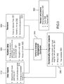
- Figure 1 displays an energy gauge with allocation of future energy consumption to a set of activities of a vehicle.
- each zone of the gauge will be proportional to the proportion of the energy consumption allocated to the corresponding activity.
- a color code and/or pictures can facilitate identification of types of activity and/or of their criticality.
- Figure 2 represents a gauge according to the invention with an indication of start and end time of each activity.
- the example which is illustrated is an aircraft, but the same gauge configuration can equip an automotive vehicle or a maritime vessel, the variations being commented upon at each relevant part of the description below.
- the gauge may be a real gauge embedded in a tactile dashboard of a vehicle, or it may be a virtual gauge embedded in a virtual dashboard on a simulation device (a PC or a tablet for instance) used by a user to prepare his/her mission.
- the gauge 210 on the right side of the figure has the form of a bar and is segmented into different activities 211, 212, 213, 214.
- activity 211 may be take-off
- activity 212 may be travelling a leg
- activity 213 may be holding above a waypoint
- activity 214 being travelling another leg.
- activity 215 is going back to the base (or Return).
- Area 216 represents a reserve of energy which cannot be used for the activities.
- activity 211 may be going out from a town
- activity 212 may be travelling a segment of a highway
- activity 213 may be going through a village
- activity 214 may be travelling another segment of a highway.
- the portions of the bar for each activity have a color or a tone which depends on the energy consumption mode assigned to the vehicle for each activity.
- the energy consumption mode depends on the power at which the engine operates which itself depends on the targeted travel speed .
- the energy consumption mode may be selected by the user. Then, the actual energy consumption will depend on the specific conditions of travel (for instance for a vehicle, it may be: resistance of air and/or terrain; traffic conditions; payload, etc.)
- the energy consumption mode may be selected among a number of possible discrete values, for example:
- These discrete values may be set by the platform (i.e. aircraft or car) manufacturer. They may be set at a percentage of the speed limit fixed by the authorities for a definite type of road, segment of road or environment (i.e. country, suburbs, center of town, etc.) The speed limits applicable for a road segment are now commonly available from most car navigation systems. Also, the discrete values may be adaptive as a function of some route profile, environmental or user defined variables like route altitude variation, wind direction and/or speed and vehicle payload. For instance, a significant tail wind will allow the percentage of the speed limit for the economy mode to be set at a higher value than if there is a significant head wind.
- the energy consumption mode may also be selected on a continuous scale. This variant is illustrated on figure 2 where a slider 221 on a bar 220 on the left side of the figure allows the user to vary the percentage of maximum consumption on scale from 100% to 0% by moving the slider on the bar. The appropriate value is selected by the user to be assigned to an activity with the slider when the said activity is selected on the activity bar 210, which is the case of activity 212 on the example illustrated by the figure.
- activity bar 210 Different elements may be displayed on the activity bar 210. For instance, for activity 212, which is selected on activity bar 210:
- a time scale 2126 may be advantageously positioned alongside the activity bar 210. It has a number of ticks (in this example 6) which is proportional to the duration of the activity, so that the user can visualize in a convenient manner the consumption of energy per unit of time.
- the energy gauge maps a quantity of energy to the Y coordinate of the screen. The whole amount of energy is mapped to Y with a single, linear, quantitative scale. Thus, each leg has a height that is proportional to the quantity of energy consumption.
- a text representing the said information is displayed next to the beginning (top) and the ending (bottom) of the representation of a leg, or in the middle of a leg for the duration.
- the ticks 2126 on the time scale the user is made aware of that particular aspect of the representation of time.
- the representation displays a tick for each minute on the time scale, but other values may of course be selected depending on the use case.
- the density of ticks depends on the ratio between the amount of energy required by an activity and its duration: the more an activity lasts, the denser the ticks are.
- activity 213 starting at 12:13 has a duration of 5 minutes
- the activity starting at 12:18 has a duration of 12 minutes, though both activities have similar height.
- the difference of density of ticks on the time scale reflects the difference of duration. Not only is the user no longer misled, but he can estimate the duration of a leg by perceiving its associated tick density, without even needing to read the duration of the activity on the display (which in this case is not displayed).
- the user can also switch to a reverse mode of mapping where time would be mapped to a single, linear, quantitative scale, while ticks would indicate the quantity of energy spent during the duration of a particular leg.
- the selection between the two display modes may be made a click on a radio-button (not represented on the figure)'linear scale" with two entries 'time" and "energy”.
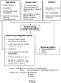
- Figure 3 represents a functional architecture of a vehicle route management system.
- the vehicle is an aircraft.
- the size of the vehicle may vary widely, from a military transport aircraft or a tanker to a micro-drone.
- the aircraft route management system of the invention comprises a user input interface, 310, whereby a user will be required to input a number of variables.
- the user input interface may be located in the vehicle or device or may be physically independent from the vehicle or device.
- the aircraft route management system of the invention may operate in a simulation mode, where the data input in the input interface do not actually control the operation of the vehicle or in a control mode where the data input will direct the operation of the vehicle.
- Input may be made using a data transfer from a file through a port of the computer, when data has been prepared in advance of the start of the mission. It can also be transferred through a network connection (wired or wireless). Input may also be made using a keyboard, a mouse, a joystick or a voice recognition interface. Part of the data to be input may use any of these data entry interfaces, or a combination thereof.
- a first of the items to be entered is a route with a plurality of waypoints (311). Two successive waypoints define a "segment".
- a segment may be rectilinear or curvilinear.
- the user may be invited by the user interface to enter only a destination point and, optionally stops en-route. The user will be then proposed a number of possible routes. In an option, if the total available energy is not enough to reach the destination point, the system may calculate an itinerary that will stop by a recharge/re-fuelling station. Therefore, the user input interface may receive data from the system data repository and from sensors (for instance an energy level sensor, a wind sensor, a light sensor or others).
- a segment has an activity associated herewith (312).
- the activity associated with a segment is going from the waypoint at the beginning of the segment to the waypoint at the end of the segment.
- An activity may be selected in types of activities, said types being dependent on the vehicle and the missions it performs.
- an energy consumption mode (313) is associated with a segment.
- energy consumption modes may be defined in a discrete manner, for example with two values, standard and economy, or three values, standard, comfort and economy. Energy consumption modes may also be defined by a continuous variable, between a minimum percentage of total power level to a maximum power level.
- entry of other data may be required from the user, for instance breaks after a predetermined maximum driving time, etc.
- the amount of data that a user is requested to input may be minimal, for instance when a predetermined list of missions with preselected segments, activities and associated energy consumption have been previously entered, and the user only has to select in the list of missions the one he/she wants to execute.
- a system data repository 320 stores and updates data which are necessary or useful to enable the system of the invention to deliver its outputs.
- the system data will comprise energy consumption parameters, 321.
- the parameters may be stored in tables specific to a vehicle model, and possibly specific to the very vehicle in which the system is embedded. Indeed, energy consumption may vary with the precise configuration of the vehicle (engine(s), batteries, form factor, number of seats, tires, load, etc%), the age of the vehicle and the time elapsed from the last maintenance operation.
- the parameters will vary as a function of the energy consumption modes. Depending on the type of vehicle (see below), the energy consumption parameters will also vary with the vertical profile of the itinerary, the traffic density, the wind speed and direction, the piloting or driving style.
- the combinations of causes of variations of the energy consumption parameters may be very numerous.
- computations may be based on a physical model and real-time simulation.
- the computations and/or parameters may be made user dependent, for instance in terms of preferences, i.e. set the maximum energy consumption mode not at the speed limit, but at 80% of the speed limit.
- the system data repository 320 also comprises a navigation unit, 322, with a map of the areas to be travelled and a route management system, capable of computing a route from a departure point to a destination point with all waypoints in between which may be of interest to the user.
- the navigation unit may only accept inputs which are made while the user is on-board the vehicle. Or it may also accept inputs transferred from a memory or from a computing device via a wired or a wireless connection, where these inputs have been prepared out of the vehicle and before the start of the mission.
- the navigation unit should be able to compute a number of possible routes based on a distance, time or energy optimization algorithm (or any combination thereof).
- the navigation unit may also accept inputs which are made from a remote control interface, for instance when the vehicle is a drone, a pilotless aircraft or a pilotless car.
- the navigation unit may be loaded with an original flight plan or route and then get change commands from the remote control interface while the vehicle is in operation, said change commands being entered by an operator or generated automatically by a route planner.
- the communication link between the navigation unit and the remote control interface may be RF (Bluetooth, Wi-Fi, cellular, satellite, etc.) or optical, and will be preferably secured.
- the system data repository 320 may also comprise a history of previous travels of the vehicle, 323, possibly classified by pilot and time referenced.
- the previous travels may be classified based on an efficiency factor, globally or for a same departure and a same destination, or for a same route, or on ranking criterion of a user.
- system data may be useful to implement the invention, for instance data from the electronic control unit diagnosis in a car or from the control systems of an aircraft (like for instance total weight on takeoff).
- the aircraft route management system of the invention When operating in a control mode, the aircraft route management system of the invention also comprises sensors, 330.
- the sensors should be capable of acquiring a Position Velocity and Time (PVT) of the vehicle (331). Often, this will be a GNSS positioning receiver.
- PVT Position Velocity and Time
- Such a receiver is configured to process the navigation signals received from a number of satellites of one or more constellations (GPS, Glonass, Beidou, Galileo, etc8), calculating a pseudo-range between the receiver and each satellite and then calculating a PVT from a minimum of four satellites.
- the precision of the calculation of the PVT may vary from 10m down to 1 cm.
- the GNSS positioning receiver may be aided by an inertial navigation system using accelerometers, gyroscopes and magnetometers to propagate a GNSS position. Also positioning on a map will increase the precision of the position, if the map is very precise.
- An alternative positioning system could be based on a LPS (Local Positioning System) network.
- Sensors also comprise an energy level gauge, 332, which delivers an absolute level of the remaining energy.
- an energy level gauge 332 which delivers an absolute level of the remaining energy.
- sensors 333 which measure environmental parameters which heavily impact energy consumption like actual slope of the road or actual traffic for a car (to be compared with the ones predicted by the navigation unit) and instantaneous wind.
- the environmental parameters may also come from an information channel accessed through a wireless communication channel, for instance meteorological data (actual or predicted).
- the aircraft route management system of the invention comprises sensor emulators, 360.
- a sensor emulator is a computer implemented input interface which allows a user to vary a value of an environmental or user dependent parameter which impact energy consumption, for instance wind direction and/or speed, traffic density, payload, etc.
- the aircraft route management system of the invention may comprise both sensors 630 and sensor emulators 660 to be able to operate both in full simulation mode and in control mode.
- a limited simulation mode is a simulation mode where energy consumption mode and route can be varied by activity to simulate the impact on energy consumption.
- Enhanced simulation mode means a simulation mode where, in addition to the parameters which the user may change in the limited simulation mode, the environmental parameters affecting energy consumption and some user dependent parameters may be simulated by the user.
- the invention may be implemented in a vehicle energy management computer, 340.
- the computer may be a dedicated hardware with a specific software implementing the methods of the invention. Or it may be a specific software running on a computer which is dedicated to another task on the vehicle.
- the energy management functions in the hardware which handles the route planning and navigation functions of the vehicle. In an aircraft, this will normally be the flight management computer (FMC).
- FMC flight management computer
- the most efficient module would probably be the car navigation system.
- the FMC may comprise two redundant processing capabilities, as well as redundant data buses and data storage facilities.
- data exchange standard formats have been defined in both industries and have to be complied with.
- data and/or the communication links may be encrypted.
- the vehicle energy management computer calculates a number of outputs 350 which are made available to the user in a dynamic and integrated way.
- Energy consumption per route segment per activity, 351 is calculated based on the energy consumption parameters, the energy consumption mode, and the environmental parameters captured by the sensors. This calculation can be made before departure, when preparing the mission, and it will be repeated dynamically while the vehicle is en-route, at defined intervals, for instance at a frequency between 1 and 30 Hz, based on actual system and sensor data or information about environmental parameters ahead of the vehicle. Some use cases may justify lower or higher frequencies.
- the result of the calculation is displayed to the user on a gauge display of the type illustrated on figure 1 or 2 .
- an activity bar will display each activity with a height proportional to the energy consumption of the activity.
- Time variables start and end time of each activity, duration of each activity, ticks on the timeline
- the activity bar will display each activity with a height proportional to the duration of each activity.
- Energy consumption may be displayed in addition, with ticks along the energy consumption scale, the number of which will be proportional to the number of units of energy consumed during an activity.
- the user will be given the opportunity of performing 'what if' simulations, 352. These simulations being use case dependent, they will commented upon with more details in relation to the specific embodiments commented upon further down in the description.
- the common features of these simulations are that the user is given the opportunity to enter variants of energy consumption modes or to alter the route (adding detours, new legs, new exercises, etc%) and measure the impact on the allocation of the remaining energy to the remaining activities, two gauge views may be visible on the dashboard, to allow a comparison between the initial scenario and the alternative scenario.
- a simulation of an allocation of a cost budget to a selection of activities wherein said cost budget is a weighted combination of energy, time and range.
- the pilot could choose to minimize his/her travel time or environmental footprint, or he/she could choose to maximize endurance or range. This may be the case for a guided aircraft, for instance in an environment contaminated by radiation or pollutants.
- data may be sent from the vehicle energy management computer to a vehicle fleet management system, so that a fleet manager can perform on his/her end 'what if' simulations to optimize travels of the vehicles of the fleet present in an area or tasked with a similar activity potentially by re-allocating tasks.
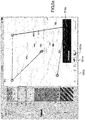
- Figure 4 illustrates a simulation of a variation of a number of travel parameters, in some embodiments of the invention.
- the aircraft route management system of the invention allows the user to directly find the maximum speed of travel with a slider, in order to investigate the impact of speed on energy consumption.
- the user can also directly manipulate the waypoints on the map in order to investigate the maximum reachable distance ( figure 4 ).
- the gauge of figure 2 is represented on figure 4 integrated in a dashboard of a vehicle.
- Figure 4 illustrates an embodiment of the invention applied to an aircraft, but it may be easily applied to an automotive vehicle.
- the legs between the waypoints will not be linear but curvilinear.
- the navigation unit is capable of calculating the curvilinear legs representing different possible routes to travel from a first waypoint to a second waypoint.
- activity 412 When activity 412 is active, it is possible to move the slider 421 to change the energy consumption mode, for instance from 50% to 60%. In a variant, it is possible to add an increase or to subtract a decrease to the energy consumption of all activities at the same time (provided that the energy consumption of each activity remains higher than 0%, or than a predefined threshold, and lower than 100%), using a button or another slider (not represented on the figure).
- the user can directly manipulate the legs/activities on the gauge and control their duration.
- a user can manipulate an arrival time for a leg in order to meet a deadline (e.g. a rendezvous), and investigate the impact of a faster travel on energy consumption.
- Direct manipulation of an arrival time of a leg in the energy gauge triggers the vehicle energy management computer to compute the energy consumption according to the time target.
- the continuous feedback is a color change since it represents the leg speed.
- the speed slider moves at the level corresponding to the computed speed. In this mode, the change in end time for an activity is not propagated to the earlier activities - only to the later activities.
- the system operate in a variant, where the change of end time is propagated up to the beginning of the mission, the speed at which all upstream activities are performed being adjusted proportionally up to the start of the mission.
- the simulations of a change of speed, a change of route and a change of time of arrival or departure may be combined to explore the various options and find heuristically the preferred ones according to one or several criteria (time of arrival, total energy consumption, total travelled time, etc.).
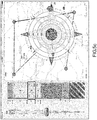
- Figures 5a , 5b and 5c illustrate simulations of variation of a number of environmental or user defined parameters, in some embodiments of the invention.
- the vehicle energy management computer computes energy consumption using environment data such as traffic density, weight (or number) of payload, or wind speed and direction.
- the user is given the opportunity to input specific data in order to perform what-if simulations to optimize travels of the vehicle. To do so, the user can perform incremental changes on the data, which automatically and continuously trigger computation and refresh of the energy gauge.
- the user can re-evaluate either the content of the mission or the day/time of the mission according to the change impact. In some configurations of the system of the invention, this can also be done during performance of the mission for the rest of the route to be travelled.
- the impact on the energy consumption is computed on the fly and visualized through continuous animated modification of the height/duration of the legs in the energy gauge.
- the user can see legs slightly enlarging or shrinking as a feed-forward of data modification.
- a direct manipulation device is available from the map, allowing the user to perform what-if simulation on the data:
- the user can select an activity or a group of activities on the map, and tune the level of traffic density by adjusting a parameter of traffic density displayed on the screen, 510a (in this case on a scale from 0% to 100%.
- the energy consumption is updated by the aircraft route management system.
- the height and duration of the legs are consequently modified in the energy gauge.
- the user can evaluate the best conditions of traffic to execute a prepared mission in order to choose a day or time of departure.
- the user can change the prepared mission to adapt it according to the conditions of traffic that he/she has just input.
- Button 521a is available on the display unit to select this simulation option.
- Another button 522a may be available from the icon bar 520a. Once the option is selected, another horizontal slider similar to traffic density slider 510a will pop up to specify the total weight of passengers/freight. The weight may be specified in kilos or in units to be transported (i.e. number of passengers; number of containers).
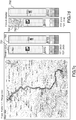
- Figures 5b and 5c illustrate a change in wind speed and direction: the user can tune speed and direction of the wind by direct manipulation of a vector on the map.
- the user presses circle 510b at the extremity of the wind vector 520b and drags it around so that it is moved to circle 510c and vector 520c, which is longer than vector 520b.
- this move represents a change in direction and speed from 220°, 20 knots to 86°, 37 knots.
- the energy consumption is updated in real-time by the aircraft route management system according to the new values of wind direction and speed.
- the height and duration indications of the activities are consequently modified on the energy gauge. See activities representations in the gauge of figures 5b and 5c ).
- the user can evaluate the best conditions of wind to execute a prepared mission in order to choose a day or time of departure.
- the user can change the prepared mission to adapt it according to the conditions of wind that he/she has just input.
- the three parameters can be modified in combination, for example:
- Wind is an important factor, not only for aircrafts but also for terrestrial vehicles. Actually, taking account of wind information in the system is important for ground-based vehicles such as cars and trucks in that counter wind, or "head winds” or wind resistance can greatly negatively impair speed and increase the required energy to complete a journey. See Jayakumar, F. Ingrosso, G. Rizzoni, J. Meyer and J. Doering, "Crowd sourced energy estimation in connected vehicles,” Electric Vehicle Conference (IEVC), 2014 IEEE International, Florence, 2014, pp. 1-8 .
- IEVC Electric Vehicle Conference
- cars can travel on roads that are protected from wind (under a cliff, behind hills or in a dense forest), conversely to aircraft which cannot avoid wind. Thus, some parts of the journey may benefit from the protection from wind, depending on its direction. If the map contains information about terrain elevation and terrain nature, the system can leverage this knowledge to adapt the predicted energy consumption accordingly.
- the elevation information can be especially useful for small UAVs that travel a low altitude, as they can benefit from the protection offered by cliffs and hills. One can then draw a path that follows the elevation (valleys, cliffs) and investigate its impact on energy consumption.
- the device enables the user to switch direction in order to see the difference of energy consumption between the two possible directions.
- elevation and vegetation information from specific maps may be used in the system.
- the vehicle When the vehicle is a drone, it is possible to take advantage of changing wind directions thanks to wind breaks provided for by cliffs, trees or buildings on the route. By accessing this information on the map used to simulate and then control the mission, the route of the drone may be made to go through the most protected zones to minimize energy consumption.
- Figure 6 represents a functional architecture of a vehicle energy management system, which is not covered by the invention.
- the architecture of the vehicle energy management system displayed on figure 6 is identical to the architecture displayed on figure 3 , with some variants because of the specific usage of a terrestrial vehicle.
- Driving modes will be defined for instance in relation to the maximum authorized speeds on an itinerary: normal mode will be a mode where the driver will drive at the speed limit; eco mode will be a mode where the driver will drive at a reduced speed (i.e. a percentage of maximum speed which is lower than 100%) to optimize consumption.
- an emergency situation automatically detected or triggered by the pilot/driver, may override the energy consumption modes, including the maximum speed limit.
- the traffic conditions are normally provided by the navigation unit through which receives them from a service provider through a communication link.
- parametric data with for instance three type of traffic conditions, highway, road, urban, to which energy consumption parameters will be associated. Some of the data may be determined statistically, e.g. on mornings (from 7 to 9am), there are queues of a certain length at some exits of highways.
- the sensors will capture vehicle position, fuel quantity (or State of Charge, SoC, for an electrical vehicle) and actual environmental conditions, for instance wind, rain, road surface, and/or slope. Recharge stations may be marked as not available at a moment in time (closed, no more recharge capacity available, etc.).
- the range attainable with the remaining fuel/SoC can be displayed directly on the route map.
- a current and a forecast SoC can be displayed vis-à-vis each recharging station on the route.
- the total energy cost of the travel/mission may also be displayed, as well as the production of greenhouse gases, total driving time or total travel time.
- Each waypoint on the map can have a number of items of data displayed either permanently or when passing over the waypoint.
- Sensor emulators are also available to offer enhanced simulation capabilities, in addition to simulations of change of route, speed or time of arrival, so that the user gets the opportunity to simulate the impact of traffic conditions, payload and/or wind direction and/or speed on energy consumption and time of arrival.
- Figures 7a to 7d represent a car navigation display with energy gauges in different configurations.
- the energy gauges are those of figure 1 . But they may be easily substituted by the gauges of figure 2 . Also the maps on the figures can be supplemented with the improvements displayed on figures 4 , 5a , 5b and 5c without difficulty.
- Figure 7a illustrates a scenario where a user prepares a trip and intends to use a normal energy consumption mode, i.e. drive at the speed limit.
- the driver plans his/her travel and makes some decisions about the way to manage the global trip.
- the driver After having entered in the system the departure and destination points in the car navigation system, the driver will be presented with a number of proposed itineraries, with a number of associated parameters: total distance, estimated travel time or time of arrival, quality of traffic, etc...
- the system will integrate other data, such as Refueling/Recharging Stations (RS), highway tolls, accommodation, food and/or leisure activities possibly associated to the RS, driving and meteorological conditions (coming from external systems), and the driver's choices on the driving mode (i.e. Max Speed - at the speed limit, Medium or Eco), implying different energy consumption rates on the legs of the different zones or sectors of the travel (i.e.
- the driver may select a mode for an activity/leg and another mode for another activity/leg.
- the mode may also be automatically selected.
- the automatic mode selection may be based on preferences of the user.
- the departure point is the city of Toulouse (France), 710, and the destination point the ski resort of Les Angles (France), 750, we assume that the driver chooses the Max Speed mode, but decides not to stop at RS1, 720, shortly after the departure.
- the system will display to the driver at the time of planning the trip a totally red gauge, 721, meaning that the solution is not acceptable, because the consumption is too high to reach RS2.
- the driver could choose to stop at RS1, but it doesn't make sense, as it is time-consuming and useless. The driver will then try to find a less consuming solution, depicted on figure 7b , which is an example of re-planning what if simulation.
- the driver runs a what if scenario by modifying the driving mode, changing from "Max Speed" to "Eco” on one or a plurality of zones of the "Departure to RS2" leg.
- the system finally shows only two parallel gauges 751, 752 for 2 legs and different values for Total Driving Time (2H00 instead of 1H50) and Total Travel Time (2H30 instead of 2H50).
- Figure 7d represents the gauges 761, 762 displayed during the travel, with the upper part of the gauge showing in dark, all along the leg, the consumed quantities, 763.
- All these planning/simulation exercises can be combined with interactive graphical simulations of an impact of a change in energy consumption mode, speed and/or time of departure or arrival, as displayed on figure 4 . They can also be combined with graphical simulations of an impact of a change in traffic conditions, weight of payload and/or wind direction and/or speed. Thanks to these improvements, the planning and optimization capability of an automotive vehicle energy management system may be greatly improved.
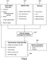
- Figure 8 represents a functional architecture of an aircraft route management system in a number of embodiments of the invention in aerospace vehicles.
- elements of the route planning, 310 which characterize a flight are a combination of waypoints on the ground and altitudes which are entered in the flight plan that may contain altitude information.
- a flight plan is generally prepared before the mission, possibly but not necessarily on a specific computer not located on-board.
- the flight plan is then transferred to the flight management computer.
- the take-off weight is an important input. It can also be a system data calculated from the SoC of the tanks, the number of passengers and the cargo.
- the planned power settings for each leg may also be entered, possibly, by the user.
- the systems performance and the A/C performance comprise level flight speed as a function of power, weight, altitude and other parameters, climb rate as a function of power, weight, altitude and other parameters, glide ratio as a function of weight, altitude and other parameters etc.
- the planned wind and temperature are also important parameters, because they will significantly impact, notably the first parameter, the energy consumption.
- the sensors, 330 will provide the A/C position, the SoC and the measured wind and temperature. In case of strong headwind, the system will take into account that the ground speed will be reduced, thus increasing consumption for the leg.
- sensor emulators 360 are also available to offer full simulation capabilities, in addition to simulations of change of route, speed or time of arrival, so that the user gets the opportunity to simulate the impact of traffic conditions, payload and/or wind direction and/or speed on energy consumption and time of arrival.
- the traffic conditions will for instance be the traffic density at the airport of departure or arrival.
- the Dynamically Integrated Outputs 350 will include, among possible other variables, the Energy consumption per leg, the Estimated SoC, the Estimated Range, the Extra energy and its corresponding Estimated Range.
- the aircraft has a specific mission, for example exercises, for a training aircraft, an estimated exercises time, or the number of holding patterns it is possible to fly in case of immediate return.
- time of departure from a waypoint and time of arrival at a waypoint will be among the dynamically integrated output to be displayed on the energy gauge together with a representation of the time of the type displayed on figure 2 .
- Figure 9 represents the gauge of figure 1 with a match to the activities of an aircraft.
- the gauge of figure 1 can be easily substituted by the gauge of figure 2 , according to the invention. Also maps can be presented to the pilot in the aircraft or at the time of preparing the flight with the improvements displayed on figures 4 , 5a , 5b and 5c without difficulty.
- the gauge comprises symbols representative of activity/flight phases matching defined below:
- time of departure from a waypoint and time of arrival at a waypoint will be among the dynamically integrated output to be displayed on the energy gauge together with a representation of the time of the type displayed on figure 2 .
- the system offers full simulation capabilities, in addition to simulations of change of route, speed or time of arrival, so that the user gets the opportunity to simulate the impact of traffic conditions, payload and/or wind direction and/or speed on energy consumption and time of arrival.
- traffic conditions will for instance be the traffic density at the airport of departure and/or arrival.
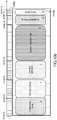
- Figures 10a , 10b and 10c represent different views of a resource management system, not covered by the invention.
- Project management involves resource management and time management. According to standard operating procedures which are commonly applied to project management, notably when a project management software of the Microsoft ProjectTM or MS ProjectTM type is used, a project is broken down in work packages (WP), each project is represented by a bar chart on a timeline with a start and an end date, using a Gantt representation. Resources may be allocated to each WP. The inventors do not know of any Gantt representation which would present the resources consumed by a WP (or planned to be consumed by a WP) in a way which would easily display what are:
- WPs WPs, Opportunity Study (WP1), Concept Phase (WP2), Solution Definition (WP3), Solution Development (WP4), Acceptance & Testing (WP5), Deployment (WP6), are represented by horizontal bars 1011a, 1012a, 1013a, 1014a, 1015a, 1016a.
- Time is represented on time bar 1020a, with a start time 1021a and an end time 1022a for WP1.
- the width of each individual bar is proportional to the product of the duration of the WP times the resources allocated to the WP.
- 2 employees are allocated to each of WP1 and WP5, 1 employee is allocated to each of WP2, WP3 and WP6.
- ticks represented for each WP on the time scale that time units between the start time and the end time of the WP.
- all calendar days are deemed to be working days, which is a simplification, but of course, calculating in working days instead of calendar days can be easily achieved with MS Project or a like software.
- the user can simulate the impact on total energy budget consumed.
- WP6 benefits from the allocation of a 2 nd employee and, thus, the resource budget allocated to this WP increases to 10 men * days, which is reflected on the figure, on bar 1016b.
- the ticks 1036b on the time bar are only 2,5, to reflect the shortened time needed. Addition (or suppression) of a resource may be performed at any time of the project.
- the user can display the WPs using a time scale.
- the representation is close to a Gantt classic representation, but the user can easily visualize the differences in staffing of the WPs thanks to their different colors/tones. Also, the amount of resources is displayed on each WP bar. It is possible to switch between the two representations easily, for instance using a button (not represented).
- the resource bars and time bar may be vertical instead of horizontal.
- the time and resources representation may be inverted, like in the case of energy management for a vehicle, as described above.
- resources needed to implement the project may also be represented on a second resource bar or a third resource bar (not represented on the figures).
- Such resources may be computer resources, network resources or others.
- Incidents in the management of the project can also be represented and/or simulated (not represented on the figures). For instance, if one or more resources are not available, the resource budget and the time needed to complete a WP and the project will be recomputed and represented on the bars.
- Figure 11 represents an energy management system for a mobile portable device not covered by the invention.
- a portable mobile communication device such as a smart phone, a tablet or a laptop, may now be used for a number of different activities, like watching a video in streaming mode or from the disk of the device, to listen to music in the same modes, to browse the Internet, to communicate with other users, via voice, SMS or e-mails, to locate the user via a GNSS receiver and/or motion sensors, etc
- the communication may be established with servers or other devices either via a land local area or wide area network, via a Wi-Fi, a Bluetooth or a cellular network connection
- the Radio Resource Control (RRC) protocol defines, for instance for W-CDMA communication channels, a CELL-DCH state (Dedicated Channel state), a CELL-FACH state (Forward Access Channel state), a CELL-PCH state (Paging Channel state) and an URA-PCH state (URA Paging Channel state), in addition to a Sleep state.
- the battery drain of CELL-FACH state is 50% of the CELL-DCH state.
- Use cases may be defined to map a definite activity to one of the RRC states
- Figure 11 represents an example of an energy consumption bar of the type of figure 2 , where the activities performed with a vehicle have been replaced by activities performed with a portable mobile communication device, for example:
- Each activity bar is represented in a color or tone corresponding to the network usage state/battery drain: activity 1111 is performed using a maximum battery drain state (CELL-DCH). It can be also set to a lower value, using for instance a slider (not represented on the figure), if the user accepts a degradation of the resolution of the video, the other activities. Likewise for the e-mail retrieval activity.1115. The other activities are performed using a lower battery drain factor (50% for activities 1112 and 1116, 30% for activity 1113, 10% for activity 1114. Also, these values may be defined by the user, using the same slider, when the user selects a definite activity, when he/she has predefined the activities to be performed in a time horizon.
- CELL-DCH maximum battery drain state
- the remaining battery is represented by bar 1117 and a reserve by bar 1118.
- simulations of the impact of variations of the energy consumption mode may also be performed, as in the case of the energy management system of a vehicle.
- a time bar 1120 with start and end times of each activity and ticks 1121 representing the number of time units corresponding to an activity may also be included alongside the activity bar.
- an impact of a change in the quality of service may be simulated.
- an impact of network density - which decreases power to acquire a base station but increases roaming - may be simulated.
- a user will have the capacity to adapt the activities performed with the device to the battery state at a moment in time.
Landscapes
- Engineering & Computer Science (AREA)
- Radar, Positioning & Navigation (AREA)
- Remote Sensing (AREA)
- Physics & Mathematics (AREA)
- General Physics & Mathematics (AREA)
- Aviation & Aerospace Engineering (AREA)
- Automation & Control Theory (AREA)
- Mechanical Engineering (AREA)
- Transportation (AREA)
- Power Engineering (AREA)
- Computer Networks & Wireless Communication (AREA)
- Mathematical Physics (AREA)
- Human Computer Interaction (AREA)
- Life Sciences & Earth Sciences (AREA)
- Sustainable Development (AREA)
- Sustainable Energy (AREA)
- Navigation (AREA)
- Traffic Control Systems (AREA)
Claims (8)
- Système de gestion d'itinéraire d'aéronef exploitable dans un mode de simulation, ou à la fois dans le mode de simulation et un mode de commande, le système comprenant :- une interface d'entrée (310) configurée pour permettre l'entrée d'un itinéraire avec une pluralité de points de cheminement, lesdits points de cheminement définissant des segments, chaque segment étant associé à une activité devant être mise en œuvre par l'aéronef dans le segment, ladite activité étant sélectionnée parmi une pluralité de types d'activité possibles, lesdits types d'activité comprenant un ou plusieurs parmi : le décollage, le parcours d'un tronçon, le maintien au-dessus d'un point de cheminement, le retour à la base, la montée, l'exercice, la descente, l'approche, la réalisation d'un circuit, et un mode de consommation d'énergie en fonction d'un pourcentage d'une consommation d'énergie maximale, d'une consommation d'énergie optimisée ou d'une puissance de fonctionnement d'un moteur de l'aéronef, ladite puissance de fonctionnement du moteur lui-même étant fonction d'une vitesse de déplacement ciblée ;- si le système de gestion d'itinéraire d'aéronef est exploitable dans le mode de commande, un ou plusieurs capteurs (330) dont la sortie est utilisée dans ledit mode de commande ;- un ou plusieurs émulateurs de capteurs (360) dont la sortie est utilisée dans ledit mode de simulation, un émulateur de capteur correspondant à une interface mise en œuvre par ordinateur permettant à un utilisateur de faire varier une valeur d'un paramètre ;- ledit un ou lesdits plusieurs capteurs et ledit un ou lesdits plusieurs émulateurs de capteurs étant configurés pour fournir une ou plusieurs parmi une position ou une estimation d'une position de l'aéronef par rapport à l'itinéraire, une ou plusieurs parmi une quantité d'énergie restante ou une estimation d'une quantité d'énergie restante et des mesures ou des estimations de variables ayant un impact sur la consommation d'énergie ;- une unité de calcul (340) configurée pour :∘ associer une consommation d'énergie prédite à chaque segment de l'itinéraire, sur la base de caractéristiques d'aéronef, de caractéristiques de segment et d'un mode de consommation d'énergie associé par un utilisateur au segment ;∘ calculer une consommation d'énergie totale prédite pour l'itinéraire ;∘ ajuster la consommation d'énergie prédite associée à chaque segment de l'itinéraire et la consommation d'énergie totale pour l'itinéraire, sur la base de sorties en provenance d'un ou plusieurs capteurs ou émulateurs de capteurs ;- une unité d'affichage (410) configurée pour présenter des sorties de l'unité de calcul et des sorties de certains dudit un ou desdits plusieurs capteurs ou émulateurs de capteurs ;
dans lequel l'unité d'affichage est en outre configurée pour présenter graphiquement la consommation d'énergie totale prédite pour l'itinéraire, par segment,
et dans lequel, suite à une variation d'un paramètre, l'unité de calcul est en outre configurée pour simuler un impact de la variation du paramètre sur la consommation d'énergie totale prédite pour l'itinéraire, par segment, et l'unité d'affichage est en outre configurée pour présenter graphiquement la consommation d'énergie totale prédite simulée pour l'itinéraire, par segment. - Système de gestion d'itinéraire d'aéronef selon la revendication 1, dans lequel l'unité d'affichage est en outre configurée pour afficher une ou plusieurs parmi une heure de début, une heure de fin d'une activité, ou une durée d'une activité.
- Système de gestion d'itinéraire d'aéronef selon la revendication 2, dans lequel l'unité d'affichage est en outre configurée pour visualiser un nombre d'unités de temps élémentaires de la durée d'une activité.
- Système de gestion d'itinéraire d'aéronef selon l'une quelconque des revendications 1 à 3, dans lequel l'unité d'affichage est en outre configurée pour afficher une interface d'entrée pour recevoir des entrées en provenance d'un ou plusieurs parmi un utilisateur ou d'un ou plusieurs des émulateurs de capteurs, lesdites entrées étant représentatives des estimations des variables ayant un impact sur la consommation d'énergie.
- Système de gestion d'itinéraire d'aéronef selon la revendication 4, dans lequel les estimations des paramètres ayant un impact sur la consommation d'énergie comprennent un ou plusieurs parmi une vitesse ou une direction du vent, une variation d'altitude de l'aéronef, une densité de trafic ou un poids ou un volume d'une charge utile de l'aéronef.
- Système de gestion d'itinéraire d'aéronef selon l'une quelconque des revendications 1 à 5, dans lequel l'unité de calcul est en outre configurée pour simuler une allocation d'un budget de coût à une sélection d'activités, dans lequel ledit budget de coût correspond à une combinaison pondérée d'énergie, de temps, de distance et de charge utile.
- Procédé de gestion d'itinéraire d'aéronef utilisable dans un mode de simulation, ou à la fois dans le mode de simulation et dans un mode de commande, ledit procédé comprenant les étapes consistant à :- recevoir, en entrée, par l'intermédiaire d'une interface d'entrée, un itinéraire avec une pluralité de points de cheminement, lesdits points de cheminement définissant des segments, chaque segment étant associé à une activité devant être mise en œuvre par l'aéronef dans le segment, ladite activité étant sélectionnée parmi une pluralité de types d'activité possibles, lesdits types d'activité comprenant un ou plusieurs types parmi : le décollage, le parcours d'un tronçon, le maintien au-dessus d'un point de cheminement, le retour à la base, la montée, l'exercice, la descente, l'approche, la réalisation d'un circuit, et un mode de consommation d'énergie en fonction d'un pourcentage d'une consommation d'énergie maximale, d'une consommation d'énergie optimisée ou d'une puissance de fonctionnement d'un moteur de l'aéronef, ladite puissance de fonctionnement du moteur lui-même étant fonction d'une vitesse de déplacement ciblée ;- si le procédé est utilisé dans le mode de commande, utiliser la sortie d'un ou plusieurs capteurs ;- dans le mode de simulation, utiliser la sortie d'un ou plusieurs émulateurs de capteurs, un émulateur de capteur étant une interface mise en œuvre par ordinateur permettant à un utilisateur de faire varier une valeur d'un paramètre ;- ledit un ou lesdits plusieurs capteurs et ledit un ou lesdits plusieurs émulateurs de capteurs étant utilisés pour capturer une ou plusieurs parmi une position ou une estimation d'une position de l'aéronef par rapport à l'itinéraire, une estimation d'une quantité ou une quantité d'énergie restante et des mesures ou des estimations de paramètres ayant un impact sur la consommation d'énergie ;- amener une unité de calcul à :∘ associer une consommation d'énergie prédite à chaque segment de l'itinéraire, sur la base de caractéristiques d'aéronef, de caractéristiques de segment et d'un mode de consommation d'énergie associé par un utilisateur au segment ;∘ calculer une consommation d'énergie totale prédite pour l'itinéraire ;∘ ajuster la consommation d'énergie prédite associée à chaque segment de l'itinéraire et la consommation d'énergie totale pour l'itinéraire, sur la base de sorties en provenance dudit un ou desdits plusieurs capteurs ou émulateurs de capteurs ;- présenter, sur une unité d'affichage, des sorties de l'unité de calcul et des sorties de certains dudit un ou desdits plusieurs capteurs ou émulateurs de capteurs ;
dans lequel l'étape de présentation comprend l'étape consistant à présenter graphiquement la consommation d'énergie totale prédite pour l'itinéraire, par segment ;
et dans lequel le procédé comprend en outre, suite à une variation d'un paramètre, l'étape consistant à simuler un impact de la variation du paramètre sur la consommation d'énergie totale prédite pour l'itinéraire, par segment, et l'étape consistant à présenter graphiquement la consommation d'énergie totale prédite simulée pour l'itinéraire, par segment. - Programme informatique de gestion d'un itinéraire d'aéronef utilisable dans un mode de simulation, ou à la fois dans le mode de simulation et dans un mode de commande, lorsqu'il est exécuté sur ordinateur, comprenant :- des composants d'interface d'entrée configurés pour permettre l'entrée d'un itinéraire avec une pluralité de points de cheminement, lesdits points de cheminement définissant des segments, chaque segment étant associé à une activité devant être mise en œuvre par l'aéronef dans le segment, ladite activité étant sélectionnée parmi une pluralité de types d'activité possibles, lesdits types d'activité comprenant un ou plusieurs types parmi : le décollage, le parcours d'un tronçon, le maintien au-dessus d'un point de cheminement, le retour à la base, la montée, l'exercice, la descente, l'approche, la réalisation d'un circuit, et un mode de consommation d'énergie en fonction d'un pourcentage d'une consommation d'énergie maximale, d'une consommation d'énergie optimisée ou d'une puissance de fonctionnement d'un moteur de l'aéronef, ladite puissance de fonctionnement du moteur lui-même étant fonction d'une vitesse de déplacement ciblée ;- si le programme informatique est utilisable dans le mode de commande, des instructions de traitement configurées pour utiliser la sortie d'un ou plusieurs capteurs ;- un ou plusieurs émulateurs de capteurs, dont la sortie est utilisée dans le mode de simulation, un émulateur de capteur étant une interface mise en œuvre par ordinateur permettant à un utilisateur de faire varier une valeur d'un paramètre ;- des instructions de traitement configurées pour capturer, à partir dudit un ou desdits plusieurs capteurs ou émulateurs de capteurs, une ou plusieurs parmi une position ou une estimation d'une position de l'aéronef par rapport à l'itinéraire, une quantité ou une estimation d'une quantité d'énergie restante, et des mesures ou des estimations de variables ayant un impact sur la consommation;- des instructions de traitement de données configurées pour:∘ associer une consommation d'énergie prédite à chaque segment de l'itinéraire, sur la base de caractéristiques d'aéronef, de caractéristiques de segment et d'un mode de consommation d'énergie associé par un utilisateur au segment ;∘ calculer une consommation d'énergie totale prédite pour l'itinéraire ;∘ ajuster la consommation d'énergie prédite associée à chaque segment de l'itinéraire et la consommation d'énergie totale pour l'itinéraire, sur la base de sorties en provenance d'un ou plusieurs capteurs ou émulateurs de capteurs ;- des composants de présentation configurés pour présenter, sur une unité d'affichage, des sorties des instructions de traitement de données et des sorties de certains dudit un ou desdits plusieurs capteurs ou émulateurs de capteurs ;
dans lequel les composants de présentation sont en outre configurés pour présenter graphiquement la consommation d'énergie totale prédite pour l'itinéraire, par segment,
et, suite à une variation d'un paramètre, les instructions de traitement de données sont en outre configurées pour simuler un impact de la variation du paramètre sur la consommation d'énergie totale prédite pour l'itinéraire, par segment, et les composants de présentation sont en outre configurés pour présenter graphiquement la consommation d'énergie totale prédite simulée pour l'itinéraire, par segment.
Priority Applications (3)
| Application Number | Priority Date | Filing Date | Title |
|---|---|---|---|
| US15/580,715 US10551205B2 (en) | 2015-06-12 | 2016-06-10 | Activity based resource management system |
| PCT/EP2016/063402 WO2016198674A1 (fr) | 2015-06-12 | 2016-06-10 | Système de gestion de ressources basé sur l'activité |
| CN201680045714.1A CN108369103A (zh) | 2015-06-12 | 2016-06-10 | 基于活动的资源管理系统 |
Applications Claiming Priority (1)
| Application Number | Priority Date | Filing Date | Title |
|---|---|---|---|
| EP15305914.2A EP3104122A1 (fr) | 2015-06-12 | 2015-06-12 | Systeme de gestion d'energie pour vehicules |
Publications (2)
| Publication Number | Publication Date |
|---|---|
| EP3104123A1 EP3104123A1 (fr) | 2016-12-14 |
| EP3104123B1 true EP3104123B1 (fr) | 2020-07-08 |
Family
ID=53487318
Family Applications (2)
| Application Number | Title | Priority Date | Filing Date |
|---|---|---|---|
| EP15305914.2A Withdrawn EP3104122A1 (fr) | 2015-06-12 | 2015-06-12 | Systeme de gestion d'energie pour vehicules |
| EP16305324.2A Not-in-force EP3104123B1 (fr) | 2015-06-12 | 2016-03-23 | Système de gestion de ressources basées sur une activité |
Family Applications Before (1)
| Application Number | Title | Priority Date | Filing Date |
|---|---|---|---|
| EP15305914.2A Withdrawn EP3104122A1 (fr) | 2015-06-12 | 2015-06-12 | Systeme de gestion d'energie pour vehicules |
Country Status (5)
| Country | Link |
|---|---|
| US (2) | US20160363456A1 (fr) |
| EP (2) | EP3104122A1 (fr) |
| CN (2) | CN106428016B (fr) |
| HK (2) | HK1231549A1 (fr) |
| WO (1) | WO2016198674A1 (fr) |
Families Citing this family (75)
| Publication number | Priority date | Publication date | Assignee | Title |
|---|---|---|---|---|
| FR3023922B1 (fr) * | 2014-07-17 | 2021-04-16 | Centre Nat Detudes Spatiales Cnes | Recepteur de positionnement et de navigation a indicateur de confiance |
| DE102015211562A1 (de) * | 2015-06-23 | 2016-12-29 | Bayerische Motoren Werke Aktiengesellschaft | Verfahren zur Bestimmung eines zeitlichen Fahrtverlaufs eines Kraftfahrzeugs und Kraftfahrzeug |
| KR101856291B1 (ko) * | 2015-08-26 | 2018-05-09 | 현대자동차주식회사 | 친환경 차량의 주행가능거리 산출 시스템 및 방법 |
| FR3044757B1 (fr) * | 2015-12-08 | 2018-01-05 | Dassault Aviation | Systeme de visualisation d'informations relatives a un vol d'un aeronef et procede associe |
| CN109791409B (zh) * | 2016-09-23 | 2022-11-29 | 苹果公司 | 自主车辆的运动控制决策 |
| WO2018058268A1 (fr) | 2016-09-27 | 2018-04-05 | 深圳市大疆创新科技有限公司 | Procédé et appareil de commande de vol et dispositif de commande |
| JP6738045B2 (ja) * | 2016-10-06 | 2020-08-12 | 三菱自動車工業株式会社 | 電動車両の表示装置 |
| WO2018148699A1 (fr) * | 2017-02-13 | 2018-08-16 | The Government Of The United States Of America, As Represented By The Secretary Of The Navy | Procédé d'estimation du bilan énergétique variable dans le temps d'une collection de puits d'énergie, de récupérateurs et de dispositifs de stockage |
| DE102017202638B4 (de) * | 2017-02-20 | 2022-04-28 | Ford Global Technologies, Llc | Vorrausschauendes Wärmemanagement für Kraftfahrzeuge |
| CN106951627A (zh) * | 2017-03-15 | 2017-07-14 | 北京百度网讯科技有限公司 | 车辆自动驾驶的仿真测试方法、装置、设备及计算机可读存储介质 |
| US10641615B2 (en) * | 2017-08-11 | 2020-05-05 | Honeywell International Inc. | Methods and apparatus for displaying flight interval management data for selecting appropriate flight management settings |
| US10571287B2 (en) * | 2017-08-25 | 2020-02-25 | The Boeing Company | System and method for vehicle energy management |
| US10545025B2 (en) * | 2017-09-22 | 2020-01-28 | Telenav, Inc. | Navigation system with a system initiated inquiry and method of operation thereof |
| JP2019073056A (ja) * | 2017-10-12 | 2019-05-16 | 株式会社トプコン | 無人航空機制御装置、無人航空機、データ処理装置、無人航空機制御方法および無人航空機制御処理用プログラム |
| EP3498520B1 (fr) | 2017-12-18 | 2023-05-03 | Volvo Car Corporation | Procédé et système destinés à fournir un conseil à un occupant d'un véhicule électrique |
| US10464443B2 (en) | 2017-12-21 | 2019-11-05 | Loon Llc | Managing power of aerial vehicles |
| US10852737B2 (en) | 2018-03-22 | 2020-12-01 | Micron Technology, Inc. | Power management, dynamic routing and memory management for autonomous driving vehicles |
| CN110549904B (zh) | 2018-03-30 | 2021-07-09 | 比亚迪股份有限公司 | 电动汽车及电动汽车的续驶里程计算方法、装置 |
| US10906425B2 (en) * | 2018-04-05 | 2021-02-02 | Ford Global Technologies, Llc | Systems and methods to generate charging warnings |
| US10854091B2 (en) * | 2018-07-03 | 2020-12-01 | Honeywell International Inc. | Energy management visualization methods and systems |
| US11567632B2 (en) | 2018-07-03 | 2023-01-31 | Apple Inc. | Systems and methods for exploring a geographic region |
| FR3083897A1 (fr) * | 2018-07-11 | 2020-01-17 | Dassault Aviation | Systeme de gestion de taches d'un equipage d'aeronef lors d'une mission et procede associe |
| CN109017375B (zh) * | 2018-07-27 | 2021-04-27 | 重庆长安新能源汽车科技有限公司 | 一种整车能量分配方法、系统及电动汽车 |
| IT201800008156A1 (it) * | 2018-08-22 | 2020-02-22 | Iveco Spa | Metodo e sistema di determinazione di una causa di extra-consumo di combustibile |
| US10887396B2 (en) * | 2019-01-08 | 2021-01-05 | International Business Machines Corporation | Sensor data manipulation using emulation |
| DE102019101094A1 (de) | 2019-01-16 | 2020-07-16 | Bayerische Motoren Werke Aktiengesellschaft | Verfahren zur Routenplanung in einem Navigationssystem eines Fahrzeugs, Navigationssystem für ein Fahrzeug und Fahrzeug mit demselben |
| DE102019201800A1 (de) * | 2019-02-12 | 2020-08-13 | Continental Automotive Gmbh | Verfahren zur Trajektorienplanung eines Assistenzsystems |
| US11880255B1 (en) | 2019-02-27 | 2024-01-23 | United Services Automobile Association (Usaa) | Budgeting tool for smart devices |
| DE102019205698A1 (de) * | 2019-04-18 | 2020-10-22 | Volkswagen Aktiengesellschaft | Verfahren und Vorrichtung zum Berechnen eines Energieverbrauchs eines Kraftfahrzeugs auf einer Fahrtroute |
| CN110060515B (zh) * | 2019-04-19 | 2021-12-03 | 中国航空无线电电子研究所 | 一种基于gnss的航空器监控系统及方法 |
| US11835351B2 (en) * | 2019-07-18 | 2023-12-05 | Cummins Inc. | Optimal route planning for electric vehicles |
| CN110303908B (zh) * | 2019-07-25 | 2021-06-04 | 广州小鹏汽车科技有限公司 | 一种充电电量的推荐方法及系统 |
| KR102850001B1 (ko) * | 2019-10-02 | 2025-08-27 | 삼성전자주식회사 | 재고 관리를 위한 무인 비행체 및 그의 동작 방법 |
| CN110750106B (zh) * | 2019-10-16 | 2023-06-02 | 深圳市道通智能航空技术股份有限公司 | 无人机的安全航线生成方法、装置、控制终端和无人机 |
| CN111660869A (zh) * | 2019-12-13 | 2020-09-15 | 摩登汽车有限公司 | 电动车电耗计算方法、整车控制器、系统及汽车 |
| CN111186388A (zh) * | 2019-12-19 | 2020-05-22 | 合肥博略文化传播有限公司 | 一种基于智能定位的车辆全景展示系统 |
| CN111452619B (zh) * | 2020-01-22 | 2021-09-14 | 北京理工大学 | 电动车辆在线能耗预测方法及系统 |
| JP7010985B2 (ja) * | 2020-03-03 | 2022-01-26 | 本田技研工業株式会社 | 走行可能距離表示装置 |
| US20210356288A1 (en) | 2020-05-15 | 2021-11-18 | Apple Inc. | User interfaces for providing navigation directions |
| EP3923260B1 (fr) * | 2020-06-09 | 2026-02-18 | Honeywell International Inc. | Systèmes et procédés d'affichage d'informations sur une station de recharge hors bord pour un véhicule à mobilité aérienne en milieu urbain (uam) |
| US12033517B2 (en) | 2020-06-09 | 2024-07-09 | Honeywell International Inc. | Systems and methods for displaying off-board recharge station information for an urban air mobility (UAM) vehicle |
| CN116124172A (zh) * | 2020-06-11 | 2023-05-16 | 苹果公司 | 用于定制的导航路线的用户界面 |
| US11846515B2 (en) | 2020-06-11 | 2023-12-19 | Apple Inc. | User interfaces for customized navigation routes |
| US11845351B2 (en) | 2020-07-07 | 2023-12-19 | Honeywell International Inc. | System and method for a mission-based battery status display for electric vehicles |
| CN112068566B (zh) * | 2020-09-15 | 2024-09-10 | 阿波罗智能技术(北京)有限公司 | 引导路径确定方法及车辆的行驶控制方法、装置、设备 |
| DE102020215678A1 (de) | 2020-12-10 | 2022-06-15 | Volkswagen Aktiengesellschaft | Verfahren und Vorrichtung zur Reichweitenkontrolle für ein batteriebetriebenes Kraftfahrzeug |
| US20210108937A1 (en) * | 2020-12-21 | 2021-04-15 | Maik Sven FOX | Fleet emission control, distribution, and limits adherence |
| GB202103280D0 (en) * | 2021-03-10 | 2021-04-21 | Rolls Royce Plc | Computer-implemented methods for controlling the operation of electric and hybrid electric aircraft |
| US12281912B2 (en) | 2021-06-07 | 2025-04-22 | Apple Inc. | User interfaces for maps and navigation |
| CN119223321A (zh) | 2021-06-07 | 2024-12-31 | 苹果公司 | 用于地图和导航的用户界面 |
| CN113741509B (zh) * | 2021-07-30 | 2024-02-27 | 北京航空航天大学 | 一种高超声速滑翔飞行器下压段能量管理方法 |
| EP4177098A1 (fr) * | 2021-11-09 | 2023-05-10 | Volvo Car Corporation | Système de gestion d'énergie pour système de stockage d'énergie de véhicule |
| CN114179678B (zh) * | 2021-11-24 | 2023-07-14 | 华人运通(江苏)技术有限公司 | 车辆续航辅助控制方法、系统、存储介质及车辆 |
| EP4190618A1 (fr) | 2021-12-01 | 2023-06-07 | Carrier Corporation | Système de commande d'énergie d'un véhicule électrique |
| DE102021132807A1 (de) * | 2021-12-13 | 2023-06-15 | Joynext Gmbh | Korrektur einer Schätzung eines Energieverbrauchs eines Fahrzeugs |
| CN114235427A (zh) * | 2021-12-27 | 2022-03-25 | 中国航发沈阳发动机研究所 | 一种飞机驾驶舱内发动机状态参数显示方法及其系统 |
| US20230202334A1 (en) * | 2021-12-29 | 2023-06-29 | Rivian Ip Holdings, Llc | Power modules, systems, and methods for allocating electrical power to multiple vehicles |
| EP4257434B1 (fr) * | 2022-04-07 | 2026-02-18 | Volvo Truck Corporation | Procédé de classification de consommateurs d'énergie dans un véhicule |
| US20230347787A1 (en) * | 2022-04-29 | 2023-11-02 | Beta Air, Llc | Systems and method for battery monitoring with over charge protection |
| US11807387B1 (en) | 2022-04-30 | 2023-11-07 | Beta Air, Llc | Apparatus and methods for a fuel-based flight indicator apparatus for an electric aircraft |
| US20230373337A1 (en) * | 2022-05-17 | 2023-11-23 | Ford Global Technologies, Llc | Methods and Systems for Charging an Electric Vehicle |
| US11970294B2 (en) | 2022-05-25 | 2024-04-30 | Beta Air, Llc | Apparatus and a method for determining a resource remaining datum of an electric aircraft |
| US20230419741A1 (en) * | 2022-06-28 | 2023-12-28 | Beta Air, Llc | Assembly and method for gauging fuel of electric aircraft |
| US20240086821A1 (en) * | 2022-09-14 | 2024-03-14 | International Business Machines Corporation | Dynamic supply chain delivery options using computer simulation |
| US20240127699A1 (en) * | 2022-10-14 | 2024-04-18 | Beta Air, Llc | Apparatus and method for calculating anticipated energy consumption for electric aircraft |
| USD1072869S1 (en) * | 2022-11-21 | 2025-04-29 | Ferrari S.P.A. | Display screen with graphical user interface |
| FR3143166B1 (fr) | 2022-12-13 | 2025-01-31 | Thales Sa | Procédé de modélisation et de prédiction de la consommation électrique d'un aéronef comprenant au moins un moteur électrique, le long d'un plan de vol |
| US12311800B2 (en) * | 2022-12-21 | 2025-05-27 | Rockwell Collins, Inc. | System and method for performance prediction of electric aircraft |
| US12485791B2 (en) | 2023-02-22 | 2025-12-02 | GM Global Technology Operations LLC | Endurance mode for electric vehicle |
| JP7600289B2 (ja) * | 2023-03-16 | 2024-12-16 | 本田技研工業株式会社 | 車両代替シミュレーション装置及び車両代替シミュレーション方法 |
| FR3150170A1 (fr) * | 2023-06-22 | 2024-12-27 | Valeo Systemes Thermiques | Procédé de gestion de la consommation d’énergie électrique pour un véhicule à propulsion électrique |
| CN116985674B (zh) * | 2023-09-27 | 2024-01-26 | 江西五十铃汽车有限公司 | 一种新能源汽车电池能量管理方法及系统 |
| US20250155250A1 (en) * | 2023-11-14 | 2025-05-15 | Here Global B.V. | Method and apparatus for electric vehicle navigation |
| US20250232679A1 (en) * | 2024-01-17 | 2025-07-17 | Honeywell International Inc. | Control system and method for providing an alert indication |
| US20250252855A1 (en) * | 2024-02-02 | 2025-08-07 | Honeywell International Inc. | System for vehicle energy visualization |
Family Cites Families (28)
| Publication number | Priority date | Publication date | Assignee | Title |
|---|---|---|---|---|
| US20050049762A1 (en) * | 2003-08-26 | 2005-03-03 | Dwyer David B. | Integrated flight management and textual air traffic control display system and method |
| US7874521B2 (en) * | 2005-10-17 | 2011-01-25 | Hoshiko Llc | Method and system for aviation navigation |
| FR2894705B1 (fr) * | 2005-12-13 | 2010-11-19 | Thales Sa | Systeme de gestion de vol d'un aeronef |
| DE102007007955B4 (de) * | 2007-02-17 | 2020-06-10 | GM Global Technology Operations LLC (n. d. Ges. d. Staates Delaware) | Kraftfahrzeug mit Antriebsmotor und Navigationssystem |
| FR2916840B1 (fr) * | 2007-05-29 | 2009-09-11 | Thales Sa | Procede et dispositif de calcul d'un plan de vol |
| FR2916842B1 (fr) * | 2007-06-01 | 2010-02-26 | Thales Sa | Procede d'optimisation d'un plan de vol |
| US8112186B2 (en) * | 2007-06-13 | 2012-02-07 | The Boeing Company | Method and apparatus for managing flight planning |
| US20090150012A1 (en) * | 2007-12-10 | 2009-06-11 | Leedor Agam | System for producing a flight plan |
| FR2927377B1 (fr) * | 2008-02-12 | 2010-06-11 | Thales Sa | Procede de deformation active d'un profil aerodynamique |
| US8010242B1 (en) * | 2008-08-06 | 2011-08-30 | On Time Systems, Inc. | Flight planning system and method |
| DE102009016869A1 (de) * | 2009-04-08 | 2010-10-14 | Li-Tec Battery Gmbh | Verfahren zum Betreiben eines Fahrzeugs |
| JP5135308B2 (ja) * | 2009-09-09 | 2013-02-06 | クラリオン株式会社 | エネルギ消費量予測方法、エネルギ消費量予測装置および端末装置 |
| DE102009052853B4 (de) | 2009-11-11 | 2017-07-20 | Dr. Ing. H.C. F. Porsche Aktiengesellschaft | Verfahren zur Reichweitenabschätzung eines Kraftfahrzeugs |
| EP2385349A1 (fr) * | 2010-05-06 | 2011-11-09 | Leica Geosystems AG | Procédé et unité de guidage pour guider des moyens de transport fonctionnant sur batteries vers des stations de reconditionnement |
| US8762050B2 (en) * | 2011-09-07 | 2014-06-24 | National Tsing Hua University | Fuel-saving path planning navigation system and fuel-saving path planning method thereof |
| US8849555B2 (en) * | 2012-02-29 | 2014-09-30 | Inrix, Inc. | Fuel consumption calculations and warnings |
| US9476369B2 (en) * | 2012-04-13 | 2016-10-25 | Toyota Motor Engineering & Manufacturing North America, Inc. | Variable power output and maximum speed in drive mode |
| US9440655B2 (en) * | 2012-08-07 | 2016-09-13 | GM Global Technology Operations LLC | Method of selecting modes of operation for a hybrid vehicle |
| US9567099B2 (en) * | 2013-04-11 | 2017-02-14 | Airbus Operations (S.A.S.) | Aircraft flight management devices, systems, computer readable media and related methods |
| US9423799B1 (en) * | 2013-08-12 | 2016-08-23 | The United States Of America As Represented By The Administrator Of The National Aeronautics And Space Administration (Nasa) | Optimum strategies for selecting descent flight-path angles |
| US20150112526A1 (en) * | 2013-10-22 | 2015-04-23 | Ford Global Technologies, Llc | Vehicle system and method for at-home route planning |
| JP5642253B1 (ja) * | 2013-11-08 | 2014-12-17 | 三菱電機株式会社 | 車両用エネルギーマネジメント装置 |
| US9493089B2 (en) * | 2014-03-24 | 2016-11-15 | The Regents Of The University Of Michigan | Prediction of battery power requirements for electric vehicles |
| US10665114B2 (en) * | 2014-03-28 | 2020-05-26 | The Boeing Company | Aircraft fuel optimization analytics |
| CN106163862B (zh) * | 2014-04-04 | 2019-07-05 | 特斯拉公司 | 用于行程规划的方法和计算机可读存储介质 |
| CA2996844A1 (fr) * | 2014-08-29 | 2016-06-16 | Tzunum, Inc. | Chaine dynamique pour aeronef hybride electrique |
| FR3026177B1 (fr) * | 2014-09-22 | 2019-11-01 | Thales | Procede d'adaptation d'un segment de trajectoire d'aeronef a pente sol constante selon au moins un critere de performance |
| US9646503B2 (en) * | 2015-02-11 | 2017-05-09 | Honeywell International Inc. | Cockpit display systems and methods for generating navigation displays including landing diversion symbology |
-
2015
- 2015-06-12 EP EP15305914.2A patent/EP3104122A1/fr not_active Withdrawn
-
2016
- 2016-03-23 EP EP16305324.2A patent/EP3104123B1/fr not_active Not-in-force
- 2016-06-08 CN CN201610404788.1A patent/CN106428016B/zh not_active Expired - Fee Related
- 2016-06-10 US US15/178,762 patent/US20160363456A1/en not_active Abandoned
- 2016-06-10 WO PCT/EP2016/063402 patent/WO2016198674A1/fr not_active Ceased
- 2016-06-10 US US15/580,715 patent/US10551205B2/en not_active Expired - Fee Related
- 2016-06-10 CN CN201680045714.1A patent/CN108369103A/zh active Pending
-
2017
- 2017-05-24 HK HK17105248.0A patent/HK1231549A1/en unknown
- 2017-05-24 HK HK17105250.5A patent/HK1231550A1/en unknown
Non-Patent Citations (1)
| Title |
|---|
| None * |
Also Published As
| Publication number | Publication date |
|---|---|
| WO2016198674A1 (fr) | 2016-12-15 |
| US20180188051A1 (en) | 2018-07-05 |
| US20160363456A1 (en) | 2016-12-15 |
| CN106428016A (zh) | 2017-02-22 |
| US10551205B2 (en) | 2020-02-04 |
| CN108369103A (zh) | 2018-08-03 |
| HK1231550A1 (en) | 2017-12-22 |
| EP3104123A1 (fr) | 2016-12-14 |
| HK1231549A1 (en) | 2017-12-22 |
| CN106428016B (zh) | 2020-05-05 |
| EP3104122A1 (fr) | 2016-12-14 |
Similar Documents
| Publication | Publication Date | Title |
|---|---|---|
| EP3104123B1 (fr) | Système de gestion de ressources basées sur une activité | |
| Pak et al. | Can Urban Air Mobility become reality? Opportunities and challenges of UAM as innovative mode of transport and DLR contribution to ongoing research | |
| EP3769173B1 (fr) | Évaluation de risques pour véhicules aériens sans pilote | |
| US20250013236A1 (en) | Fleet management user interface | |
| US9759577B2 (en) | Energy resource geographical overlay | |
| Young et al. | Architecture and information requirements to assess and predict flight safety risks during highly autonomous urban flight operations | |
| US11845351B2 (en) | System and method for a mission-based battery status display for electric vehicles | |
| US11430343B2 (en) | Aircraft mission computing system comprising a mission deck | |
| EP2711913A2 (fr) | Système de gestion de plan de vol optimisé | |
| US20220035367A1 (en) | Coordination of remote vehicles using automation level assignments | |
| US9376216B2 (en) | Visual fuel predictor system | |
| Balać et al. | Towards the integration of aerial transportation in urban settings | |
| Kulik et al. | Intelligent transport systems in aerospace engineering | |
| Li et al. | Urban air mobility: A review and challenges | |
| US12518639B2 (en) | Aircraft mission calculation system indicating a risk of loss of optimality of the trajectory actually followed by the aircraft and related method | |
| Underwood et al. | Incorporation of time of arrival constraints in a trajectory optimization technology | |
| Riccardi et al. | CORUS-XUAM: Tackling urban air mobility airspace integration challenges | |
| Andreeva-Mori | Balancing predictability and flexibility through operation volume-constrained visual flight rule operations in low altitude airspaces | |
| US20260004665A1 (en) | Aircraft Operational State Detection Based on Aircraft Movement | |
| JP2026048212A (ja) | エネルギー管理装置、エネルギー管理システム、移動体、及び表示装置 | |
| Rodrigues | Energy Consumption and Greenhouse Gas Emissions of Autonomous Aerial and Ground Vehicles for Last-Mile Delivery | |
| CREEDON | Flight management systems-What are they and why are they being developed? | |
| Balaban et al. | Towards airspace rules for future UAS-based delivery | |
| Shirkey et al. | Aviation Weather Routing Tool: A Decision Aid for Manned/Unmanned Aircraft Routing |
Legal Events
| Date | Code | Title | Description |
|---|---|---|---|
| PUAI | Public reference made under article 153(3) epc to a published international application that has entered the european phase |
Free format text: ORIGINAL CODE: 0009012 |
|
| STAA | Information on the status of an ep patent application or granted ep patent |
Free format text: STATUS: THE APPLICATION HAS BEEN PUBLISHED |
|
| AK | Designated contracting states |
Kind code of ref document: A1 Designated state(s): AL AT BE BG CH CY CZ DE DK EE ES FI FR GB GR HR HU IE IS IT LI LT LU LV MC MK MT NL NO PL PT RO RS SE SI SK SM TR |
|
| AX | Request for extension of the european patent |
Extension state: BA ME |
|
| STAA | Information on the status of an ep patent application or granted ep patent |
Free format text: STATUS: REQUEST FOR EXAMINATION WAS MADE |
|
| 17P | Request for examination filed |
Effective date: 20170608 |
|
| RBV | Designated contracting states (corrected) |
Designated state(s): AL AT BE BG CH CY CZ DE DK EE ES FI FR GB GR HR HU IE IS IT LI LT LU LV MC MK MT NL NO PL PT RO RS SE SI SK SM TR |
|
| REG | Reference to a national code |
Ref country code: HK Ref legal event code: DE Ref document number: 1231550 Country of ref document: HK |
|
| STAA | Information on the status of an ep patent application or granted ep patent |
Free format text: STATUS: EXAMINATION IS IN PROGRESS |
|
| 17Q | First examination report despatched |
Effective date: 20180725 |
|
| GRAP | Despatch of communication of intention to grant a patent |
Free format text: ORIGINAL CODE: EPIDOSNIGR1 |
|
| STAA | Information on the status of an ep patent application or granted ep patent |
Free format text: STATUS: GRANT OF PATENT IS INTENDED |
|
| INTG | Intention to grant announced |
Effective date: 20200129 |
|
| RIN1 | Information on inventor provided before grant (corrected) |
Inventor name: VINOT, JEAN-LUC Inventor name: CONVERSY, STEPHANE Inventor name: DUCHEVET, ALEXANDRE Inventor name: RIEDINGER, MATHIEU Inventor name: DUPONT, CLEMENT Inventor name: LOUBRIAT, MICKAEL Inventor name: GASPARD-BOULINC, HELENE |
|
| GRAS | Grant fee paid |
Free format text: ORIGINAL CODE: EPIDOSNIGR3 |
|
| GRAA | (expected) grant |
Free format text: ORIGINAL CODE: 0009210 |
|
| STAA | Information on the status of an ep patent application or granted ep patent |
Free format text: STATUS: THE PATENT HAS BEEN GRANTED |
|
| AK | Designated contracting states |
Kind code of ref document: B1 Designated state(s): AL AT BE BG CH CY CZ DE DK EE ES FI FR GB GR HR HU IE IS IT LI LT LU LV MC MK MT NL NO PL PT RO RS SE SI SK SM TR |
|
| REG | Reference to a national code |
Ref country code: CH Ref legal event code: EP Ref country code: AT Ref legal event code: REF Ref document number: 1288929 Country of ref document: AT Kind code of ref document: T Effective date: 20200715 |
|
| REG | Reference to a national code |
Ref country code: DE Ref legal event code: R096 Ref document number: 602016039439 Country of ref document: DE |
|
| REG | Reference to a national code |
Ref country code: IE Ref legal event code: FG4D |
|
| REG | Reference to a national code |
Ref country code: LT Ref legal event code: MG4D |
|
| REG | Reference to a national code |
Ref country code: AT Ref legal event code: MK05 Ref document number: 1288929 Country of ref document: AT Kind code of ref document: T Effective date: 20200708 |
|
| REG | Reference to a national code |
Ref country code: NL Ref legal event code: MP Effective date: 20200708 |
|
| PG25 | Lapsed in a contracting state [announced via postgrant information from national office to epo] |
Ref country code: LT Free format text: LAPSE BECAUSE OF FAILURE TO SUBMIT A TRANSLATION OF THE DESCRIPTION OR TO PAY THE FEE WITHIN THE PRESCRIBED TIME-LIMIT Effective date: 20200708 Ref country code: HR Free format text: LAPSE BECAUSE OF FAILURE TO SUBMIT A TRANSLATION OF THE DESCRIPTION OR TO PAY THE FEE WITHIN THE PRESCRIBED TIME-LIMIT Effective date: 20200708 Ref country code: PT Free format text: LAPSE BECAUSE OF FAILURE TO SUBMIT A TRANSLATION OF THE DESCRIPTION OR TO PAY THE FEE WITHIN THE PRESCRIBED TIME-LIMIT Effective date: 20201109 Ref country code: FI Free format text: LAPSE BECAUSE OF FAILURE TO SUBMIT A TRANSLATION OF THE DESCRIPTION OR TO PAY THE FEE WITHIN THE PRESCRIBED TIME-LIMIT Effective date: 20200708 Ref country code: NO Free format text: LAPSE BECAUSE OF FAILURE TO SUBMIT A TRANSLATION OF THE DESCRIPTION OR TO PAY THE FEE WITHIN THE PRESCRIBED TIME-LIMIT Effective date: 20201008 Ref country code: AT Free format text: LAPSE BECAUSE OF FAILURE TO SUBMIT A TRANSLATION OF THE DESCRIPTION OR TO PAY THE FEE WITHIN THE PRESCRIBED TIME-LIMIT Effective date: 20200708 Ref country code: BG Free format text: LAPSE BECAUSE OF FAILURE TO SUBMIT A TRANSLATION OF THE DESCRIPTION OR TO PAY THE FEE WITHIN THE PRESCRIBED TIME-LIMIT Effective date: 20201008 Ref country code: ES Free format text: LAPSE BECAUSE OF FAILURE TO SUBMIT A TRANSLATION OF THE DESCRIPTION OR TO PAY THE FEE WITHIN THE PRESCRIBED TIME-LIMIT Effective date: 20200708 Ref country code: GR Free format text: LAPSE BECAUSE OF FAILURE TO SUBMIT A TRANSLATION OF THE DESCRIPTION OR TO PAY THE FEE WITHIN THE PRESCRIBED TIME-LIMIT Effective date: 20201009 Ref country code: SE Free format text: LAPSE BECAUSE OF FAILURE TO SUBMIT A TRANSLATION OF THE DESCRIPTION OR TO PAY THE FEE WITHIN THE PRESCRIBED TIME-LIMIT Effective date: 20200708 |
|
| PG25 | Lapsed in a contracting state [announced via postgrant information from national office to epo] |
Ref country code: RS Free format text: LAPSE BECAUSE OF FAILURE TO SUBMIT A TRANSLATION OF THE DESCRIPTION OR TO PAY THE FEE WITHIN THE PRESCRIBED TIME-LIMIT Effective date: 20200708 Ref country code: PL Free format text: LAPSE BECAUSE OF FAILURE TO SUBMIT A TRANSLATION OF THE DESCRIPTION OR TO PAY THE FEE WITHIN THE PRESCRIBED TIME-LIMIT Effective date: 20200708 Ref country code: LV Free format text: LAPSE BECAUSE OF FAILURE TO SUBMIT A TRANSLATION OF THE DESCRIPTION OR TO PAY THE FEE WITHIN THE PRESCRIBED TIME-LIMIT Effective date: 20200708 Ref country code: IS Free format text: LAPSE BECAUSE OF FAILURE TO SUBMIT A TRANSLATION OF THE DESCRIPTION OR TO PAY THE FEE WITHIN THE PRESCRIBED TIME-LIMIT Effective date: 20201108 |
|
| PG25 | Lapsed in a contracting state [announced via postgrant information from national office to epo] |
Ref country code: NL Free format text: LAPSE BECAUSE OF FAILURE TO SUBMIT A TRANSLATION OF THE DESCRIPTION OR TO PAY THE FEE WITHIN THE PRESCRIBED TIME-LIMIT Effective date: 20200708 |
|
| REG | Reference to a national code |
Ref country code: DE Ref legal event code: R097 Ref document number: 602016039439 Country of ref document: DE |
|
| PG25 | Lapsed in a contracting state [announced via postgrant information from national office to epo] |
Ref country code: IT Free format text: LAPSE BECAUSE OF FAILURE TO SUBMIT A TRANSLATION OF THE DESCRIPTION OR TO PAY THE FEE WITHIN THE PRESCRIBED TIME-LIMIT Effective date: 20200708 Ref country code: EE Free format text: LAPSE BECAUSE OF FAILURE TO SUBMIT A TRANSLATION OF THE DESCRIPTION OR TO PAY THE FEE WITHIN THE PRESCRIBED TIME-LIMIT Effective date: 20200708 Ref country code: DK Free format text: LAPSE BECAUSE OF FAILURE TO SUBMIT A TRANSLATION OF THE DESCRIPTION OR TO PAY THE FEE WITHIN THE PRESCRIBED TIME-LIMIT Effective date: 20200708 Ref country code: CZ Free format text: LAPSE BECAUSE OF FAILURE TO SUBMIT A TRANSLATION OF THE DESCRIPTION OR TO PAY THE FEE WITHIN THE PRESCRIBED TIME-LIMIT Effective date: 20200708 Ref country code: RO Free format text: LAPSE BECAUSE OF FAILURE TO SUBMIT A TRANSLATION OF THE DESCRIPTION OR TO PAY THE FEE WITHIN THE PRESCRIBED TIME-LIMIT Effective date: 20200708 Ref country code: SM Free format text: LAPSE BECAUSE OF FAILURE TO SUBMIT A TRANSLATION OF THE DESCRIPTION OR TO PAY THE FEE WITHIN THE PRESCRIBED TIME-LIMIT Effective date: 20200708 |
|
| PLBE | No opposition filed within time limit |
Free format text: ORIGINAL CODE: 0009261 |
|
| STAA | Information on the status of an ep patent application or granted ep patent |
Free format text: STATUS: NO OPPOSITION FILED WITHIN TIME LIMIT |
|
| PG25 | Lapsed in a contracting state [announced via postgrant information from national office to epo] |
Ref country code: AL Free format text: LAPSE BECAUSE OF FAILURE TO SUBMIT A TRANSLATION OF THE DESCRIPTION OR TO PAY THE FEE WITHIN THE PRESCRIBED TIME-LIMIT Effective date: 20200708 |
|
| 26N | No opposition filed |
Effective date: 20210409 |
|
| PG25 | Lapsed in a contracting state [announced via postgrant information from national office to epo] |
Ref country code: SK Free format text: LAPSE BECAUSE OF FAILURE TO SUBMIT A TRANSLATION OF THE DESCRIPTION OR TO PAY THE FEE WITHIN THE PRESCRIBED TIME-LIMIT Effective date: 20200708 |
|
| PG25 | Lapsed in a contracting state [announced via postgrant information from national office to epo] |
Ref country code: SI Free format text: LAPSE BECAUSE OF FAILURE TO SUBMIT A TRANSLATION OF THE DESCRIPTION OR TO PAY THE FEE WITHIN THE PRESCRIBED TIME-LIMIT Effective date: 20200708 |
|
| REG | Reference to a national code |
Ref country code: DE Ref legal event code: R119 Ref document number: 602016039439 Country of ref document: DE |
|
| PG25 | Lapsed in a contracting state [announced via postgrant information from national office to epo] |
Ref country code: MC Free format text: LAPSE BECAUSE OF FAILURE TO SUBMIT A TRANSLATION OF THE DESCRIPTION OR TO PAY THE FEE WITHIN THE PRESCRIBED TIME-LIMIT Effective date: 20200708 |
|
| REG | Reference to a national code |
Ref country code: CH Ref legal event code: PL |
|
| GBPC | Gb: european patent ceased through non-payment of renewal fee |
Effective date: 20210323 |
|
| REG | Reference to a national code |
Ref country code: BE Ref legal event code: MM Effective date: 20210331 |
|
| PG25 | Lapsed in a contracting state [announced via postgrant information from national office to epo] |
Ref country code: DE Free format text: LAPSE BECAUSE OF NON-PAYMENT OF DUE FEES Effective date: 20211001 Ref country code: FR Free format text: LAPSE BECAUSE OF NON-PAYMENT OF DUE FEES Effective date: 20210331 Ref country code: GB Free format text: LAPSE BECAUSE OF NON-PAYMENT OF DUE FEES Effective date: 20210323 Ref country code: IE Free format text: LAPSE BECAUSE OF NON-PAYMENT OF DUE FEES Effective date: 20210323 Ref country code: LI Free format text: LAPSE BECAUSE OF NON-PAYMENT OF DUE FEES Effective date: 20210331 Ref country code: LU Free format text: LAPSE BECAUSE OF NON-PAYMENT OF DUE FEES Effective date: 20210323 Ref country code: CH Free format text: LAPSE BECAUSE OF NON-PAYMENT OF DUE FEES Effective date: 20210331 |
|
| PG25 | Lapsed in a contracting state [announced via postgrant information from national office to epo] |
Ref country code: BE Free format text: LAPSE BECAUSE OF NON-PAYMENT OF DUE FEES Effective date: 20210331 |
|
| PG25 | Lapsed in a contracting state [announced via postgrant information from national office to epo] |
Ref country code: HU Free format text: LAPSE BECAUSE OF FAILURE TO SUBMIT A TRANSLATION OF THE DESCRIPTION OR TO PAY THE FEE WITHIN THE PRESCRIBED TIME-LIMIT; INVALID AB INITIO Effective date: 20160323 |
|
| PG25 | Lapsed in a contracting state [announced via postgrant information from national office to epo] |
Ref country code: CY Free format text: LAPSE BECAUSE OF FAILURE TO SUBMIT A TRANSLATION OF THE DESCRIPTION OR TO PAY THE FEE WITHIN THE PRESCRIBED TIME-LIMIT Effective date: 20200708 |
|
| REG | Reference to a national code |
Ref country code: HK Ref legal event code: WD Ref document number: 1231550 Country of ref document: HK |
|
| PG25 | Lapsed in a contracting state [announced via postgrant information from national office to epo] |
Ref country code: MK Free format text: LAPSE BECAUSE OF FAILURE TO SUBMIT A TRANSLATION OF THE DESCRIPTION OR TO PAY THE FEE WITHIN THE PRESCRIBED TIME-LIMIT Effective date: 20200708 |
|
| PG25 | Lapsed in a contracting state [announced via postgrant information from national office to epo] |
Ref country code: TR Free format text: LAPSE BECAUSE OF FAILURE TO SUBMIT A TRANSLATION OF THE DESCRIPTION OR TO PAY THE FEE WITHIN THE PRESCRIBED TIME-LIMIT Effective date: 20200708 |
|
| PG25 | Lapsed in a contracting state [announced via postgrant information from national office to epo] |
Ref country code: MT Free format text: LAPSE BECAUSE OF FAILURE TO SUBMIT A TRANSLATION OF THE DESCRIPTION OR TO PAY THE FEE WITHIN THE PRESCRIBED TIME-LIMIT Effective date: 20200708 |