EP3104202B1 - Struktur zur eliminierung von austretendem licht und faserlaser - Google Patents
Struktur zur eliminierung von austretendem licht und faserlaser Download PDFInfo
- Publication number
- EP3104202B1 EP3104202B1 EP15743598.3A EP15743598A EP3104202B1 EP 3104202 B1 EP3104202 B1 EP 3104202B1 EP 15743598 A EP15743598 A EP 15743598A EP 3104202 B1 EP3104202 B1 EP 3104202B1
- Authority
- EP
- European Patent Office
- Prior art keywords
- cladding
- covering material
- refractive index
- fiber
- optical fiber
- Prior art date
- Legal status (The legal status is an assumption and is not a legal conclusion. Google has not performed a legal analysis and makes no representation as to the accuracy of the status listed.)
- Not-in-force
Links
- 239000000835 fiber Substances 0.000 title claims description 55
- 239000000463 material Substances 0.000 claims description 100
- 238000005253 cladding Methods 0.000 claims description 96
- 239000013307 optical fiber Substances 0.000 claims description 74
- 238000007526 fusion splicing Methods 0.000 claims description 21
- 238000005086 pumping Methods 0.000 claims description 21
- 239000011347 resin Substances 0.000 claims description 19
- 229920005989 resin Polymers 0.000 claims description 19
- 230000001902 propagating effect Effects 0.000 claims description 6
- 230000005855 radiation Effects 0.000 claims description 5
- 230000020169 heat generation Effects 0.000 description 7
- 238000011144 upstream manufacturing Methods 0.000 description 7
- 238000010586 diagram Methods 0.000 description 6
- VYPSYNLAJGMNEJ-UHFFFAOYSA-N Silicium dioxide Chemical compound O=[Si]=O VYPSYNLAJGMNEJ-UHFFFAOYSA-N 0.000 description 5
- 230000003287 optical effect Effects 0.000 description 3
- 230000002787 reinforcement Effects 0.000 description 3
- LFQSCWFLJHTTHZ-UHFFFAOYSA-N Ethanol Chemical compound CCO LFQSCWFLJHTTHZ-UHFFFAOYSA-N 0.000 description 2
- 238000010521 absorption reaction Methods 0.000 description 2
- 229910052681 coesite Inorganic materials 0.000 description 2
- 229910052906 cristobalite Inorganic materials 0.000 description 2
- 229920000642 polymer Polymers 0.000 description 2
- 229910052761 rare earth metal Inorganic materials 0.000 description 2
- 239000000377 silicon dioxide Substances 0.000 description 2
- 229910052682 stishovite Inorganic materials 0.000 description 2
- 229910052905 tridymite Inorganic materials 0.000 description 2
- 229910000838 Al alloy Inorganic materials 0.000 description 1
- 229910052782 aluminium Inorganic materials 0.000 description 1
- XAGFODPZIPBFFR-UHFFFAOYSA-N aluminium Chemical compound [Al] XAGFODPZIPBFFR-UHFFFAOYSA-N 0.000 description 1
- 239000000919 ceramic Substances 0.000 description 1
- 238000005520 cutting process Methods 0.000 description 1
- 230000006866 deterioration Effects 0.000 description 1
- 230000000694 effects Effects 0.000 description 1
- 230000005284 excitation Effects 0.000 description 1
- 230000004927 fusion Effects 0.000 description 1
- 150000002500 ions Chemical class 0.000 description 1
- 230000031700 light absorption Effects 0.000 description 1
- 238000004519 manufacturing process Methods 0.000 description 1
- 229910052751 metal Inorganic materials 0.000 description 1
- 239000002184 metal Substances 0.000 description 1
- 238000000034 method Methods 0.000 description 1
- 230000000644 propagated effect Effects 0.000 description 1
- 238000004506 ultrasonic cleaning Methods 0.000 description 1
Images


Classifications
-
- H—ELECTRICITY
- H01—ELECTRIC ELEMENTS
- H01S—DEVICES USING THE PROCESS OF LIGHT AMPLIFICATION BY STIMULATED EMISSION OF RADIATION [LASER] TO AMPLIFY OR GENERATE LIGHT; DEVICES USING STIMULATED EMISSION OF ELECTROMAGNETIC RADIATION IN WAVE RANGES OTHER THAN OPTICAL
- H01S3/00—Lasers, i.e. devices using stimulated emission of electromagnetic radiation in the infrared, visible or ultraviolet wave range
- H01S3/09—Processes or apparatus for excitation, e.g. pumping
- H01S3/091—Processes or apparatus for excitation, e.g. pumping using optical pumping
- H01S3/094—Processes or apparatus for excitation, e.g. pumping using optical pumping by coherent light
- H01S3/094003—Processes or apparatus for excitation, e.g. pumping using optical pumping by coherent light the pumped medium being a fibre
- H01S3/094007—Cladding pumping, i.e. pump light propagating in a clad surrounding the active core
-
- G—PHYSICS
- G02—OPTICS
- G02B—OPTICAL ELEMENTS, SYSTEMS OR APPARATUS
- G02B6/00—Light guides; Structural details of arrangements comprising light guides and other optical elements, e.g. couplings
- G02B6/24—Coupling light guides
- G02B6/245—Removing protective coverings of light guides before coupling
-
- G—PHYSICS
- G02—OPTICS
- G02B—OPTICAL ELEMENTS, SYSTEMS OR APPARATUS
- G02B6/00—Light guides; Structural details of arrangements comprising light guides and other optical elements, e.g. couplings
- G02B6/24—Coupling light guides
- G02B6/26—Optical coupling means
- G02B6/264—Optical coupling means with optical elements between opposed fibre ends which perform a function other than beam splitting
-
- H—ELECTRICITY
- H01—ELECTRIC ELEMENTS
- H01S—DEVICES USING THE PROCESS OF LIGHT AMPLIFICATION BY STIMULATED EMISSION OF RADIATION [LASER] TO AMPLIFY OR GENERATE LIGHT; DEVICES USING STIMULATED EMISSION OF ELECTROMAGNETIC RADIATION IN WAVE RANGES OTHER THAN OPTICAL
- H01S3/00—Lasers, i.e. devices using stimulated emission of electromagnetic radiation in the infrared, visible or ultraviolet wave range
- H01S3/02—Constructional details
- H01S3/04—Arrangements for thermal management
- H01S3/0405—Conductive cooling, e.g. by heat sinks or thermo-electric elements
-
- H—ELECTRICITY
- H01—ELECTRIC ELEMENTS
- H01S—DEVICES USING THE PROCESS OF LIGHT AMPLIFICATION BY STIMULATED EMISSION OF RADIATION [LASER] TO AMPLIFY OR GENERATE LIGHT; DEVICES USING STIMULATED EMISSION OF ELECTROMAGNETIC RADIATION IN WAVE RANGES OTHER THAN OPTICAL
- H01S3/00—Lasers, i.e. devices using stimulated emission of electromagnetic radiation in the infrared, visible or ultraviolet wave range
- H01S3/05—Construction or shape of optical resonators; Accommodation of active medium therein; Shape of active medium
- H01S3/06—Construction or shape of active medium
- H01S3/063—Waveguide lasers, i.e. whereby the dimensions of the waveguide are of the order of the light wavelength
- H01S3/067—Fibre lasers
- H01S3/06704—Housings; Packages
-
- H—ELECTRICITY
- H01—ELECTRIC ELEMENTS
- H01S—DEVICES USING THE PROCESS OF LIGHT AMPLIFICATION BY STIMULATED EMISSION OF RADIATION [LASER] TO AMPLIFY OR GENERATE LIGHT; DEVICES USING STIMULATED EMISSION OF ELECTROMAGNETIC RADIATION IN WAVE RANGES OTHER THAN OPTICAL
- H01S3/00—Lasers, i.e. devices using stimulated emission of electromagnetic radiation in the infrared, visible or ultraviolet wave range
- H01S3/05—Construction or shape of optical resonators; Accommodation of active medium therein; Shape of active medium
- H01S3/06—Construction or shape of active medium
- H01S3/063—Waveguide lasers, i.e. whereby the dimensions of the waveguide are of the order of the light wavelength
- H01S3/067—Fibre lasers
- H01S3/06708—Constructional details of the fibre, e.g. compositions, cross-section, shape or tapering
-
- H—ELECTRICITY
- H01—ELECTRIC ELEMENTS
- H01S—DEVICES USING THE PROCESS OF LIGHT AMPLIFICATION BY STIMULATED EMISSION OF RADIATION [LASER] TO AMPLIFY OR GENERATE LIGHT; DEVICES USING STIMULATED EMISSION OF ELECTROMAGNETIC RADIATION IN WAVE RANGES OTHER THAN OPTICAL
- H01S3/00—Lasers, i.e. devices using stimulated emission of electromagnetic radiation in the infrared, visible or ultraviolet wave range
- H01S3/05—Construction or shape of optical resonators; Accommodation of active medium therein; Shape of active medium
- H01S3/06—Construction or shape of active medium
- H01S3/063—Waveguide lasers, i.e. whereby the dimensions of the waveguide are of the order of the light wavelength
- H01S3/067—Fibre lasers
- H01S3/06708—Constructional details of the fibre, e.g. compositions, cross-section, shape or tapering
- H01S3/06729—Peculiar transverse fibre profile
-
- H—ELECTRICITY
- H01—ELECTRIC ELEMENTS
- H01S—DEVICES USING THE PROCESS OF LIGHT AMPLIFICATION BY STIMULATED EMISSION OF RADIATION [LASER] TO AMPLIFY OR GENERATE LIGHT; DEVICES USING STIMULATED EMISSION OF ELECTROMAGNETIC RADIATION IN WAVE RANGES OTHER THAN OPTICAL
- H01S3/00—Lasers, i.e. devices using stimulated emission of electromagnetic radiation in the infrared, visible or ultraviolet wave range
- H01S3/09—Processes or apparatus for excitation, e.g. pumping
- H01S3/091—Processes or apparatus for excitation, e.g. pumping using optical pumping
- H01S3/094—Processes or apparatus for excitation, e.g. pumping using optical pumping by coherent light
- H01S3/0941—Processes or apparatus for excitation, e.g. pumping using optical pumping by coherent light of a laser diode
-
- G—PHYSICS
- G02—OPTICS
- G02B—OPTICAL ELEMENTS, SYSTEMS OR APPARATUS
- G02B6/00—Light guides; Structural details of arrangements comprising light guides and other optical elements, e.g. couplings
- G02B6/10—Light guides; Structural details of arrangements comprising light guides and other optical elements, e.g. couplings of the optical waveguide type
- G02B6/14—Mode converters
-
- G—PHYSICS
- G02—OPTICS
- G02B—OPTICAL ELEMENTS, SYSTEMS OR APPARATUS
- G02B6/00—Light guides; Structural details of arrangements comprising light guides and other optical elements, e.g. couplings
- G02B6/24—Coupling light guides
- G02B6/255—Splicing of light guides, e.g. by fusion or bonding
-
- G—PHYSICS
- G02—OPTICS
- G02B—OPTICAL ELEMENTS, SYSTEMS OR APPARATUS
- G02B6/00—Light guides; Structural details of arrangements comprising light guides and other optical elements, e.g. couplings
- G02B6/24—Coupling light guides
- G02B6/255—Splicing of light guides, e.g. by fusion or bonding
- G02B6/2558—Reinforcement of splice joint
-
- G—PHYSICS
- G02—OPTICS
- G02B—OPTICAL ELEMENTS, SYSTEMS OR APPARATUS
- G02B6/00—Light guides; Structural details of arrangements comprising light guides and other optical elements, e.g. couplings
- G02B6/24—Coupling light guides
- G02B6/42—Coupling light guides with opto-electronic elements
- G02B6/4296—Coupling light guides with opto-electronic elements coupling with sources of high radiant energy, e.g. high power lasers, high temperature light sources
-
- H—ELECTRICITY
- H01—ELECTRIC ELEMENTS
- H01S—DEVICES USING THE PROCESS OF LIGHT AMPLIFICATION BY STIMULATED EMISSION OF RADIATION [LASER] TO AMPLIFY OR GENERATE LIGHT; DEVICES USING STIMULATED EMISSION OF ELECTROMAGNETIC RADIATION IN WAVE RANGES OTHER THAN OPTICAL
- H01S3/00—Lasers, i.e. devices using stimulated emission of electromagnetic radiation in the infrared, visible or ultraviolet wave range
- H01S3/09—Processes or apparatus for excitation, e.g. pumping
- H01S3/091—Processes or apparatus for excitation, e.g. pumping using optical pumping
- H01S3/094—Processes or apparatus for excitation, e.g. pumping using optical pumping by coherent light
- H01S3/094049—Guiding of the pump light
- H01S3/094053—Fibre coupled pump, e.g. delivering pump light using a fibre or a fibre bundle
-
- H—ELECTRICITY
- H01—ELECTRIC ELEMENTS
- H01S—DEVICES USING THE PROCESS OF LIGHT AMPLIFICATION BY STIMULATED EMISSION OF RADIATION [LASER] TO AMPLIFY OR GENERATE LIGHT; DEVICES USING STIMULATED EMISSION OF ELECTROMAGNETIC RADIATION IN WAVE RANGES OTHER THAN OPTICAL
- H01S3/00—Lasers, i.e. devices using stimulated emission of electromagnetic radiation in the infrared, visible or ultraviolet wave range
- H01S3/09—Processes or apparatus for excitation, e.g. pumping
- H01S3/091—Processes or apparatus for excitation, e.g. pumping using optical pumping
- H01S3/094—Processes or apparatus for excitation, e.g. pumping using optical pumping by coherent light
- H01S3/09408—Pump redundancy
Definitions
- the present invention relates to a leakage light removal structure, and more particularly to a leakage light removal structure for removing leakage light produced at a fusion splicing point of an optical fiber in a fiber laser or the like.
- a covering material is removed from an end of each optical fiber by a predetermined length to expose a cladding.
- those two optical fibers are connected to each other by fusion splicing.
- Fig. 1 shows two optical fibers fused in such a manner. With the structure shown in Fig. 1 , two optical fibers 510 and 610 are fused together within a space surrounded by a reinforcement member 500. A downstream end of a covering material 520 of the optical fiber 510 is removed over its whole circumference, and an upstream end of a covering material 620 of the optical fiber 610 is removed over its whole circumference. An exposed end of a cladding 530 of the optical fiber 510 and an exposed end of a cladding 630 of the optical fiber 610 are fused at a fusion splicing point 700.
- the covering material 620 of the output optical fiber 610 has a refractive index higher than a refractive index of the cladding 630, the leakage light produced in the cladding 630 of the optical fiber 610 is introduced into the covering material 620 from the cladding 630 and absorbed therein.
- the covering material 620 covers the whole circumference of the cladding 630. Therefore, the leakage light produced in the cladding 630 is locally emitted to the covering material 620 at the most upstream part 642 of the covering material 620 that covers the cladding 630. Accordingly, the leakage light is locally absorbed in the covering material 620 at the most upstream part 642. This absorption may cause generation of heat or a serious accident such as fire.
- Patent Literature 1 JP 2009-116076 A
- JP 2011 186399 A by OMRON TATEISI ELECTRONICS CO dated 22 September 2011 discloses an optical fiber connecting structure for suppressing the increase of the temperature of two optical fibers by leakage light leaking out from the fusion part of the optical fibers
- WO 2007/148127 A3 GSI GROUP LIMITED dated 27 December 2007 discloses a fibre laser system is provided with at least one means for protecting one or more components from damage caused by errant radiation.
- the present invention has been made in view of the above drawbacks of the prior art. It is, therefore, a first object of the present invention to provide a leakage light removal structure that can efficiently remove leakage light produced in an optical fiber without causing local heat generation or fire.
- a second object of the present invention is to provide a fiber laser capable of emitting a high-quality laser beam with high reliability.
- a leakage light removal structure that can efficiently remove leakage light produced in an optical fiber without causing local heat generation or fire.
- the leakage light removal structure is used to remove leakage light in an optical fiber having a core, a cladding covering the core and having a refractive index lower than the core, and a covering material covering the cladding having a refractive index higher than the cladding.
- the leakage light removal structure has a fiber housing that houses part of the optical fiber, a covering material extension portion covering part of a whole circumference of the cladding by extending part of the covering material along a longitudinal direction of the optical fiber within the fiber housing, and a cladding exposure portion in which a portion of the whole circumference of the cladding other than the covering material extension portion is exposed within the fiber housing.
- the cladding exposure portion is covered with a medium or a resin having a refractive index lower than the refractive index of the cladding.
- the covering material extension portion extends only over part of the whole circumference of the cladding. Therefore, the amount of the leakage light emitted into the covering material at the most upstream part of the covering material extension portion can be reduced as compared to a conventional structure in which the whole circumference of the cladding is covered with the covering material. Accordingly, it is possible to suppress local heat generation caused by leakage light absorbed in the covering material and thus to improve the reliability of the leakage light removal structure.
- a fiber laser capable of emitting a high-quality laser beam with high reliability.
- the fiber laser has a signal light generator operable to generate signal light, a pump laser diode operable to generate pump light, and a clad pumping fiber.
- the clad pumping fiber has a core through which the signal light propagates, a cladding which covers the core and through which the pump light propagates, and a covering material covering the cladding and having a refractive index higher than a refractive index of the cladding.
- the fiber laser has an output optical fiber connected to the clad pumping fiber by fusion splicing and the aforementioned leakage light removal structure configured to remove leakage light produced in the cladding of the output optical fiber.
- the covering material extension portion In order to suppress local heat generation more effectively, it is preferable to form the covering material extension portion with a range of angles equal to or less than 180° about an axis of the optical fiber in a cross-section perpendicular to the axis.
- the refractive index of the medium or the resin covering the cladding exposure portion should preferably be lower than the refractive index of the covering material.
- the fiber housing should preferably include a heat radiator plate having a good thermal radiation characteristic, which is disposed so as to face the cladding exposure portion.
- a leakage light removal structure of the present invention it is possible to efficiently remove leakage light and to suppress local heat generation due to emission of the leakage light to improve the reliability. Furthermore, according to a fiber laser of the present invention, there can be provided a fiber laser capable of emitting a high-quality laser beam with high reliability.
- Fig. 2 is a schematic diagram showing a fiber laser 1 according to a first embodiment of the present invention.
- the fiber laser 1 has a signal light generator 10 operable to generate signal light, a plurality of pump laser diodes (LDs) 20 operable to generate pump light, an optical coupler 30 operable to couple the signal light from the signal light generator 10 and pump light from the pump LDs 20 and to output the coupled light, a clad pumping fiber 40 having an end connected to an output end 32 of the optical coupler 30, an output optical fiber 140 connected to an output end 42 of the clad pumping fiber 40, and an isolator 52 provided on the output optical fiber 140.
- LDs pump laser diodes
- Fig. 3 is a cross-sectional view schematically showing the clad pumping fiber 40.
- the clad pumping fiber 40 includes a core 60 for transmitting signal light generated by the signal light generator 10, a cladding (inner cladding) 62 covering the core 60, and a covering material (outer cladding) 64 covering the cladding 62.
- the core 60 is formed of SiO 2 doped with a rare earth element such as Yb.
- the core 60 serves as a signal light waveguide for transmitting the signal light.
- the cladding 62 is formed of a material having a refractive index lower than a refractive index of the core 60 (e.g., SiO 2 ).
- the covering material 64 is formed of a resin having a refractive index lower than the refractive index of the cladding 62 (e.g., polymer with a low refractive index).
- the cladding 62 serves as a pump light waveguide for transmitting the pump light.
- signal light from the signal light generator 10 propagates within the core 60
- pump light from the pump LDs 20 propagates within the cladding 62 and the core 60. While the pump light propagates through the core 60, ions of the rare earth element doped in the core 60 absorbs the pump light to cause excitation. Thus, the signal light propagating through the core 60 is amplified by stimulated emission.
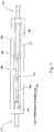
- Fig. 4 is a diagram schematically showing a structure of a fusion splicing portion between optical fibers according to a first embodiment of the present invention
- Fig. 5 is a cross-sectional view taken along line V-V of Fig. 4
- the clad pumping fiber 40 and the output optical fiber 140 which is located downstream of the clad pumping fiber 40, are connected to each other by fusion splicing within a fiber housing 72 that is substantially in the form of a rectangular parallelepiped.
- a downstream end of the covering material 64 is removed over the whole circumference of the clad pumping fiber 40, and an upstream end of the covering material 64 is removed over the whole circumference of the output optical fiber 140.
- the exposed end of the cladding 62 of the clad pumping fiber 40 and the exposed end of the cladding 162 of the output optical fiber 140 are connected to each other at a fusion splicing point 180 by fusion splicing.
- the covering material 164 of the output optical fiber 140 has a refractive index higher than a refractive index of the cladding 162.
- the reference numeral 160 in Fig. 5 denotes a core of the output optical fiber 140.
- a leakage light removal structure 70 is provided for removing such leakage light.
- a portion of the covering material 164 is removed over a part of the whole circumference of the output optical fiber 140, for example, within a range of angles equal to or more than 180° (e.g., 180°) about an axis of the output optical fiber 140 in a cross-section perpendicular to that axis ( Fig. 5 ). Therefore, the covering material 164 is exposed from the cladding 162 within this range so as to form a cladding exposure portion 174.
- a covering material extension portion 175 is formed by extending a portion of the covering material 164 along a longitudinal direction of the output optical fiber 140 within a range of angles equal to or less than 180° about the axis of the output optical fiber 140. As shown in Fig. 4 , this covering material extension portion 175 extends along the longitudinal direction of the output optical fiber 140 by a predetermined length.
- an interior of the fiber housing 72 is filled with a resin (e.g., UV curable resin) 76 having a refractive index that is lower than the refractive index of the cladding 162 of the output optical fiber 140 and the refractive index of the covering material 164 at a wavelength being used.
- the cladding exposure portion 174 and the covering material extension portion 175 are covered with this resin 76.
- the reference numeral 77 in Fig. 4 denotes a hard resin material, which seals the interior of the fiber housing 72.
- the leakage light that has propagated through the cladding 162 reaches an interface between the cladding 162 and the covering material extension portion 175, it enters the covering material extension portion 175 because the refractive index of the covering material extension portion 175 is equal to or higher than the refractive index of the cladding 162.
- the leakage light is emitted to the covering material extension portion 175. Accordingly, it is possible to prevent generation of heat or fire that would be caused on a downstream side of the leakage light removal structure 70 by leakage light.
- the reliability of the emission optics can be improved.
- the covering material extension portion 175. only part of the whole circumference of the cladding 162 is covered with the covering material extension portion 175. Therefore, the amount of the leakage light emitted into the covering material 164 at the most upstream part of the covering material extension portion 175 can be reduced as compared to the conventional structure shown in Fig. 1 in which the whole circumference of the cladding is covered with the covering material. Accordingly, it is possible to suppress local heat generation caused by leakage light absorbed in the covering material 164 and thus to improve the reliability of the leakage light removal structure 70. At that time, the covering material extension portion 175 may cover part of the whole circumference of the cladding 162.
- a covering material extension portion 175 with an angle that is equal to or less than 180° about the axis of the output optical fiber 140 in a cross-section ( Fig. 5 ) perpendicular to that axis.
- the resin 76 covering the covering material 164 has a refractive index lower than that of the covering material 164. Therefore, leakage light emitted into the covering material 164 is confined in the covering material 164 and absorbed in the covering material 164 while it propagates through the covering material 164.
- the amount of leakage light per unit length can be reduced as compared to the conventional structure. Thus, the total amount of generated heat can be reduced.
- a portion of the fiber housing 72 is formed by a heat radiator plate 78 having good thermal radiation characteristics.
- the heat radiator plate 78 is disposed so as to face the covering material extension portion 175.
- heat generated in the covering material 164 by the leakage light emitted into the covering material 164 can effectively be radiated through the heat radiator plate 78.
- Examples of such a heat radiator plate 78 include metal plates having a surface anodized with aluminum or aluminum alloy.
- the aforementioned covering material extension portion 175 can be formed with use of an apparatus 80 as shown in Fig. 8.
- the apparatus 80 has holders 82 for holding opposite ends of the output optical fiber 140 and a blade 84 in the form of a plane for shaving a surface of the output optical fiber 140.
- the output optical fiber 140 is first held by the holders 82. In that state, the blade 84 is brought into contact with the surface of the output optical fiber 140 and moved in a longitudinal direction of the output optical fiber 140 by a certain distance. Thus, the covering material 164 present on the surface of the output optical fiber 140 is peeled by the certain distance so as to expose the cladding 162 from the covering material 164.
- the output optical fiber 140 held by the holders 82 is rotated through 20° about its axis, and the blade 84 is moved back to the original position. Thereafter, the blade 84 is brought into contact with the surface of the output optical fiber 140 again and moved in the longitudinal direction of the output optical fiber 140 by the same distance as moved previously.
- the covering material 164 is similarly peeled by the certain distance so as to expose the cladding 162 from the covering material 164.
- the above operation is repeated nine times in total to expose the cladding 162 from the covering material 164 with a range of 180° about the axis of the output optical fiber 140 in the cross-section perpendicular to that axis ( Fig. 5 ).
- the aforementioned covering material extension portion 175 is formed. In this manner, the size of the covering material extension portion 175 can be controlled by the number of shaving processes with the blade 84 and a rotation angle of the clad pumping fiber 40.
- the present embodiment describes an example in which the cladding exposure portion 174 and the covering material extension portion 175 are covered with the resin 76.
- the cladding exposure portion 174 and the covering material extension portion 175 may not be covered with the resin 76.
- the cladding exposure portion 174 and the covering material extension portion 175 may be covered with a medium (air or the like) that has a refractive index lower than the refractive index of the cladding 162 (and the refractive index of the covering material 164).
- the covering material extension portion 175 In order to prevent the covering material extension portion 175 from being peeled from the surface of the cladding 162 and to promote absorption of heat from leakage light absorbed in the covering material extension portion 175, it is preferable to cover the cladding exposure portion 174 and the covering material extension portion 175 with the resin 76 as in the present embodiment. Furthermore, this resin 76 may be filled into the air cladding 182 within the fiber housing 72.
- the optical fibers 510 and 610 included a core having a diameter of 10 ⁇ m and a cladding 530 or 630 having a diameter of 400 ⁇ m.
- An end of each of the covering materials 520 and 620 of the optical fibers 510 and 610 was removed along its axial direction by 20 mm so as to expose the claddings 530 and 630.
- Ultrasonic cleaning with ethanol was conducted to clean surfaces of the exposed claddings 530 and 630.
- a reinforcement member 500 formed of a ceramic member having a coefficient of linear expansion that was adjusted to that of quartz glass, the claddings 530 and 630 of the optical fibers 510 and 610 were jointed and fused to each other. Opposite ends of the reinforcement member 500 and the optical fibers 510 and 610 were fixed with a hard UV curable resin.
- the fiber laser was operated at an output of 600 W.
- the most upstream part 642 of the covering material 620 was locally heated as expected and increased in temperature to about 90°C.
- the covering material 620 suffers from heat deterioration when the temperature of the covering material 620 increases during a production process. Then the amount of absorption of light increases, which causes an increased temperature of the covering material 620. Thus, negative feedback is generated.
- the lifetime of the covering material 620 used at that time was about 20,000 hours. It was found that the covering material 620 had a very short lifetime.
- a light removal structure 70 as shown in Fig. 4 was produced in the same manner.
- a resin (polymer cladding) having a refractive index of 1.37 was used for the covering material 164 of the output optical fiber 140, and a UV curable resin having a refractive index of 1.32 was used for the resin 76.
- the same components as used in the aforementioned conventional leakage light removal structure were used for components other than the aforementioned components.
- the covering material extension portion 175 was produced with use of the apparatus shown in Fig. 8. Specifically, the blade 84 was brought into contact with a surface of the output optical fiber 140 held by the holders 82 and moved in a longitudinal direction of the output optical fiber 140 by 30 mm to expose the cladding 162 from the covering material 164. Then the output optical fiber 140 was rotated through 20° about its axis. This cutting process was performed nine times to expose the cladding 162 with an angle of 180° in total.
- the fiber laser was operated under the same conditions as the test for the conventional leakage light removal structure.
- the greatest temperature increase of the covering material extension portion 175 was as low as 55°C. Thus, it was found that local temperature increase was reduced.
- the lifetime of the covering material 164 was calculated based on this result of the temperature increase, it would be 90,000 hours or more. Thus, it is found that the lifetime can overwhelmingly be extended as compared to the conventional leakage light removal structure.
- the present invention is suitable for use in a leakage light removal structure for removing leakage light produced at a fusion splicing point of optical fibers or the like in a fiber laser.
Landscapes
- Physics & Mathematics (AREA)
- Electromagnetism (AREA)
- Optics & Photonics (AREA)
- Engineering & Computer Science (AREA)
- Plasma & Fusion (AREA)
- General Physics & Mathematics (AREA)
- Microelectronics & Electronic Packaging (AREA)
- Lasers (AREA)
- Mechanical Coupling Of Light Guides (AREA)
- Optical Fibers, Optical Fiber Cores, And Optical Fiber Bundles (AREA)
- Optical Couplings Of Light Guides (AREA)
Claims (5)
- Streulichtentfernungsstruktur zum Entfernen von Streulicht in einer optischen Faser (140) mit einem Kern (160), einer den Kern (160) bedeckenden Umhüllung (162) mit einem Brechungsindex, der niedriger als ein Brechungsindex des Kerns (160) ist, und einem Abdeckmaterial (164), das einen Teil der Umhüllung (162) bedeckt und einen Brechungsindex aufweist, der größer als der Brechungsindex der Umhüllung (162) ist, wobei die Streulichtentfernungsstruktur umfasst:ein Fasergehäuse (72), das einen Teil der optischen Faser (140) aufnimmt;einen Abdeckmaterialverlängerungsabschnitt (175), der einen Teil eines gesamten Umfangs der Umhüllung (162) radial abdeckt, indem er einen Teil des Abdeckmaterials (164) entlang einer Längsrichtung der optischen Faser (140) innerhalb des Fasergehäuses (72) verlängert; undeinen Umhüllungsfreilegungsabschnitt (174), in dem ein Abschnitt des gesamten Umfangs der Umhüllung (162), der nicht der Abdeckmaterialverlängerungsabschnitt (175) ist, innerhalb des Fasergehäuses (72) freiliegt, wobei der Umhüllungsfreilegungsabschnitt (174) mit einem Medium oder einem Harz (76) mit einem Brechungsindex, der kleiner als der Brechungsindex der Umhüllung (162) ist, abgedeckt ist.
- Streulichtentfernungsstruktur nach Anspruch 1, worin der Abdeckmaterialverlängerungsabschnitt (175) mit einem Winkelbereich von gleich oder weniger als 180° um eine Achse der optischen Faser (140) in einem Querschnitt senkrecht zur Achse ausgebildet ist.
- Streulichtentfernungsstruktur nach Anspruch 1 oder 2, worin der Brechungsindex des Mediums oder des Harzes (76), das den Umhüllungsfreilegungsabschnitt (174) bedeckt, kleiner ist als der Brechungsindex des Abdeckmaterials (164).
- Streulichtentfernungsstruktur nach einem der Ansprüche 1 bis 3, worin das Fasergehäuse (72) eine Wärmeabstrahlungsplatte (78) aufweist, die so angeordnet ist, dass sie dem Umhüllungsfreilegungsabschnitt (174) zugewandt ist, wobei die Wärmeabstrahlungsplatte (78) eine gute Wärmeabstrahlungscharakteristik aufweist.
- Faserlaser, umfassend:einen Signallichtgenerator (10), der zum Erzeugen von Signallicht betreibbar ist;eine Pumplaserdiode (20), die zum Erzeugen von Pumplicht betreibbar ist;eine umhüllte Pumpfaser (40) mit einem Kern (60), durch den sich das Signallicht ausbreitet, einer den Kern (60) bedeckenden Umhüllung (62) und einem die Umhüllung (62) bedeckenden Abdeckmaterial (64), das einen Brechungsindex aufweist, der größer ist als ein Brechungsindex der Umhüllung (62), wobei sich das Pumplicht durch die Umhüllung (62) ausbreitet;eine Ausgangsoptischefaser (140), die mit der umhüllten Pumpfaser (40) durch Fusionsspleißen verbunden ist; unddie Streulichtentfernungsstruktur (70), gemäß einem der Ansprüche 1 bis 4, wobei die Streulichtentfernungsstruktur (70) konfiguriert ist, um Streulicht zu entfernen, das in der Umhüllung (162) der Ausgangsoptischefaser (140) erzeugt wird.
Applications Claiming Priority (2)
| Application Number | Priority Date | Filing Date | Title |
|---|---|---|---|
| JP2014018602A JP6010566B2 (ja) | 2014-02-03 | 2014-02-03 | 漏れ光除去構造及びファイバレーザ |
| PCT/JP2015/052807 WO2015115637A1 (ja) | 2014-02-03 | 2015-02-02 | 漏れ光除去構造及びファイバレーザ |
Publications (3)
| Publication Number | Publication Date |
|---|---|
| EP3104202A1 EP3104202A1 (de) | 2016-12-14 |
| EP3104202A4 EP3104202A4 (de) | 2017-11-01 |
| EP3104202B1 true EP3104202B1 (de) | 2018-12-05 |
Family
ID=53757202
Family Applications (1)
| Application Number | Title | Priority Date | Filing Date |
|---|---|---|---|
| EP15743598.3A Not-in-force EP3104202B1 (de) | 2014-02-03 | 2015-02-02 | Struktur zur eliminierung von austretendem licht und faserlaser |
Country Status (5)
| Country | Link |
|---|---|
| US (1) | US10431951B2 (de) |
| EP (1) | EP3104202B1 (de) |
| JP (1) | JP6010566B2 (de) |
| CN (1) | CN105980897B (de) |
| WO (1) | WO2015115637A1 (de) |
Families Citing this family (13)
| Publication number | Priority date | Publication date | Assignee | Title |
|---|---|---|---|---|
| CN105068181B (zh) * | 2015-08-28 | 2018-04-10 | 清华大学 | 一种光纤包层光滤除器及其制造方法 |
| CN105044836B (zh) * | 2015-09-08 | 2018-04-10 | 清华大学 | 一种用于光纤的包层光滤除器及其制造方法、光纤激光器 |
| CN105633778B (zh) * | 2016-03-28 | 2019-05-10 | 中国人民解放军国防科学技术大学 | 高阶模滤除光纤端面泵浦耦合器及其制作方法 |
| JP6317388B2 (ja) * | 2016-04-18 | 2018-04-25 | 株式会社フジクラ | 光ファイバ融着接続構造及びレーザ装置の製造方法 |
| JP6381591B2 (ja) | 2016-08-01 | 2018-08-29 | 株式会社フジクラ | 補強構造 |
| JP6295305B1 (ja) | 2016-10-04 | 2018-03-14 | 株式会社フジクラ | 光ファイバ及びファイバレーザ |
| JP6357207B2 (ja) * | 2016-10-04 | 2018-07-11 | 株式会社フジクラ | 光ファイバ及びファイバレーザ |
| JP6356856B1 (ja) * | 2017-03-28 | 2018-07-11 | 株式会社フジクラ | クラッドモード光除去構造及びレーザ装置 |
| CN108919423A (zh) * | 2018-05-25 | 2018-11-30 | 深圳技术大学(筹) | 一种光纤熔接点处理方法及装置 |
| CN110361809B (zh) * | 2019-07-05 | 2020-12-22 | 深圳联品激光技术有限公司 | 光纤、光纤包层功率滤除器、光纤激光器及光纤制备方法 |
| WO2021155036A1 (en) * | 2020-01-30 | 2021-08-05 | Nlight, Inc. | Thermal path optimized optical signal combiner housing |
| EP4127838B1 (de) * | 2020-03-29 | 2024-04-24 | Soreq Nuclear Research Center | Aufheizen einer atom-gedampften zell mitttels einer optischen faser |
| TWI789166B (zh) * | 2021-12-14 | 2023-01-01 | 搏盟科技股份有限公司 | 漸變式光纖包層光剝除器及其製造方法 |
Family Cites Families (10)
| Publication number | Priority date | Publication date | Assignee | Title |
|---|---|---|---|---|
| JPS63214630A (ja) * | 1987-03-02 | 1988-09-07 | Sumitomo Electric Ind Ltd | 圧力センサ |
| US5926600A (en) * | 1997-05-22 | 1999-07-20 | Litton Systems, Inc. | Optical fiber for reducing optical signal reflections |
| US5995697A (en) * | 1997-11-19 | 1999-11-30 | Northern Telecom Limited | Partially coated grating optical fibre, method of producing same and fibre telecommunications system |
| US6549712B2 (en) * | 2001-05-10 | 2003-04-15 | 3M Innovative Properties Company | Method of recoating an optical fiber |
| US7251401B2 (en) * | 2005-09-16 | 2007-07-31 | Matshsita Electric Industrial Co., Ltd. | Fiber coating processing and slitting for non-confined light leakage |
| WO2007148127A2 (en) * | 2006-06-23 | 2007-12-27 | Gsi Group Limited | Fibre laser system |
| JP2009069492A (ja) * | 2007-09-13 | 2009-04-02 | Omron Corp | 光ファイバおよび光学装置 |
| JP2009116076A (ja) * | 2007-11-07 | 2009-05-28 | Mitsubishi Electric Corp | 光ファイバ融着部保持構造 |
| JP5434703B2 (ja) * | 2010-03-11 | 2014-03-05 | オムロン株式会社 | 光ファイバ接続構造、レーザ照射装置およびレーザ加工装置 |
| JP5621930B2 (ja) * | 2011-06-29 | 2014-11-12 | パナソニック株式会社 | ファイバレーザ |
-
2014
- 2014-02-03 JP JP2014018602A patent/JP6010566B2/ja not_active Expired - Fee Related
-
2015
- 2015-02-02 CN CN201580007037.XA patent/CN105980897B/zh not_active Expired - Fee Related
- 2015-02-02 WO PCT/JP2015/052807 patent/WO2015115637A1/ja not_active Ceased
- 2015-02-02 EP EP15743598.3A patent/EP3104202B1/de not_active Not-in-force
-
2016
- 2016-08-01 US US15/225,181 patent/US10431951B2/en active Active
Non-Patent Citations (1)
| Title |
|---|
| None * |
Also Published As
| Publication number | Publication date |
|---|---|
| WO2015115637A1 (ja) | 2015-08-06 |
| US10431951B2 (en) | 2019-10-01 |
| JP2015145960A (ja) | 2015-08-13 |
| JP6010566B2 (ja) | 2016-10-19 |
| CN105980897B (zh) | 2019-04-23 |
| US20160336711A1 (en) | 2016-11-17 |
| EP3104202A1 (de) | 2016-12-14 |
| CN105980897A (zh) | 2016-09-28 |
| EP3104202A4 (de) | 2017-11-01 |
Similar Documents
| Publication | Publication Date | Title |
|---|---|---|
| EP3104202B1 (de) | Struktur zur eliminierung von austretendem licht und faserlaser | |
| EP3104201B1 (de) | Struktur zur eliminierung von überschüssigem licht und faserlaser | |
| JP4954737B2 (ja) | 光増幅システム、これを用いた光ファイバレーザ及び光ファイバ増幅器 | |
| JP5621930B2 (ja) | ファイバレーザ | |
| US8433161B2 (en) | All glass fiber laser cladding mode stripper | |
| JP5260885B2 (ja) | 光ファイバの漏洩光処理構造 | |
| JP5786143B2 (ja) | ファイバー部品及びレーザ装置 | |
| JP2017208563A (ja) | 高パワーで液体冷却された励起光および信号光の結合器 | |
| WO2007116792A1 (ja) | 光学部品の光入出力端およびビーム変換装置 | |
| JP2007293298A (ja) | 光学部品の光入出力端 | |
| EP3188327B1 (de) | Glasfaservorrichtung | |
| US10833470B2 (en) | Optical fiber and fiber laser | |
| WO2014129023A1 (ja) | 漏れ光除去部品、コンバイナ、光増幅器及びファイバレーザ装置 | |
| CN108603983B (zh) | 光学模块及光输出装置 | |
| EP4007089B1 (de) | Faserlaservorrichtung | |
| JP6026147B2 (ja) | 光コネクタ |
Legal Events
| Date | Code | Title | Description |
|---|---|---|---|
| PUAI | Public reference made under article 153(3) epc to a published international application that has entered the european phase |
Free format text: ORIGINAL CODE: 0009012 |
|
| STAA | Information on the status of an ep patent application or granted ep patent |
Free format text: STATUS: REQUEST FOR EXAMINATION WAS MADE |
|
| 17P | Request for examination filed |
Effective date: 20160901 |
|
| AK | Designated contracting states |
Kind code of ref document: A1 Designated state(s): AL AT BE BG CH CY CZ DE DK EE ES FI FR GB GR HR HU IE IS IT LI LT LU LV MC MK MT NL NO PL PT RO RS SE SI SK SM TR |
|
| AX | Request for extension of the european patent |
Extension state: BA ME |
|
| DAX | Request for extension of the european patent (deleted) | ||
| A4 | Supplementary search report drawn up and despatched |
Effective date: 20171005 |
|
| RIC1 | Information provided on ipc code assigned before grant |
Ipc: H01S 3/067 20060101ALI20170928BHEP Ipc: G02B 6/44 20060101ALI20170928BHEP Ipc: G02B 6/255 20060101AFI20170928BHEP Ipc: G02B 6/02 20060101ALI20170928BHEP |
|
| GRAP | Despatch of communication of intention to grant a patent |
Free format text: ORIGINAL CODE: EPIDOSNIGR1 |
|
| STAA | Information on the status of an ep patent application or granted ep patent |
Free format text: STATUS: GRANT OF PATENT IS INTENDED |
|
| INTG | Intention to grant announced |
Effective date: 20180619 |
|
| GRAS | Grant fee paid |
Free format text: ORIGINAL CODE: EPIDOSNIGR3 |
|
| GRAA | (expected) grant |
Free format text: ORIGINAL CODE: 0009210 |
|
| STAA | Information on the status of an ep patent application or granted ep patent |
Free format text: STATUS: THE PATENT HAS BEEN GRANTED |
|
| AK | Designated contracting states |
Kind code of ref document: B1 Designated state(s): AL AT BE BG CH CY CZ DE DK EE ES FI FR GB GR HR HU IE IS IT LI LT LU LV MC MK MT NL NO PL PT RO RS SE SI SK SM TR |
|
| REG | Reference to a national code |
Ref country code: GB Ref legal event code: FG4D |
|
| REG | Reference to a national code |
Ref country code: CH Ref legal event code: EP |
|
| REG | Reference to a national code |
Ref country code: AT Ref legal event code: REF Ref document number: 1073783 Country of ref document: AT Kind code of ref document: T Effective date: 20181215 |
|
| REG | Reference to a national code |
Ref country code: IE Ref legal event code: FG4D |
|
| REG | Reference to a national code |
Ref country code: DE Ref legal event code: R096 Ref document number: 602015020922 Country of ref document: DE |
|
| REG | Reference to a national code |
Ref country code: NL Ref legal event code: MP Effective date: 20181205 |
|
| REG | Reference to a national code |
Ref country code: AT Ref legal event code: MK05 Ref document number: 1073783 Country of ref document: AT Kind code of ref document: T Effective date: 20181205 |
|
| REG | Reference to a national code |
Ref country code: LT Ref legal event code: MG4D |
|
| PG25 | Lapsed in a contracting state [announced via postgrant information from national office to epo] |
Ref country code: AT Free format text: LAPSE BECAUSE OF FAILURE TO SUBMIT A TRANSLATION OF THE DESCRIPTION OR TO PAY THE FEE WITHIN THE PRESCRIBED TIME-LIMIT Effective date: 20181205 Ref country code: LT Free format text: LAPSE BECAUSE OF FAILURE TO SUBMIT A TRANSLATION OF THE DESCRIPTION OR TO PAY THE FEE WITHIN THE PRESCRIBED TIME-LIMIT Effective date: 20181205 Ref country code: NO Free format text: LAPSE BECAUSE OF FAILURE TO SUBMIT A TRANSLATION OF THE DESCRIPTION OR TO PAY THE FEE WITHIN THE PRESCRIBED TIME-LIMIT Effective date: 20190305 Ref country code: FI Free format text: LAPSE BECAUSE OF FAILURE TO SUBMIT A TRANSLATION OF THE DESCRIPTION OR TO PAY THE FEE WITHIN THE PRESCRIBED TIME-LIMIT Effective date: 20181205 Ref country code: ES Free format text: LAPSE BECAUSE OF FAILURE TO SUBMIT A TRANSLATION OF THE DESCRIPTION OR TO PAY THE FEE WITHIN THE PRESCRIBED TIME-LIMIT Effective date: 20181205 Ref country code: LV Free format text: LAPSE BECAUSE OF FAILURE TO SUBMIT A TRANSLATION OF THE DESCRIPTION OR TO PAY THE FEE WITHIN THE PRESCRIBED TIME-LIMIT Effective date: 20181205 Ref country code: BG Free format text: LAPSE BECAUSE OF FAILURE TO SUBMIT A TRANSLATION OF THE DESCRIPTION OR TO PAY THE FEE WITHIN THE PRESCRIBED TIME-LIMIT Effective date: 20190305 Ref country code: HR Free format text: LAPSE BECAUSE OF FAILURE TO SUBMIT A TRANSLATION OF THE DESCRIPTION OR TO PAY THE FEE WITHIN THE PRESCRIBED TIME-LIMIT Effective date: 20181205 |
|
| PGFP | Annual fee paid to national office [announced via postgrant information from national office to epo] |
Ref country code: DE Payment date: 20190206 Year of fee payment: 5 Ref country code: GB Payment date: 20190205 Year of fee payment: 5 |
|
| PG25 | Lapsed in a contracting state [announced via postgrant information from national office to epo] |
Ref country code: AL Free format text: LAPSE BECAUSE OF FAILURE TO SUBMIT A TRANSLATION OF THE DESCRIPTION OR TO PAY THE FEE WITHIN THE PRESCRIBED TIME-LIMIT Effective date: 20181205 Ref country code: SE Free format text: LAPSE BECAUSE OF FAILURE TO SUBMIT A TRANSLATION OF THE DESCRIPTION OR TO PAY THE FEE WITHIN THE PRESCRIBED TIME-LIMIT Effective date: 20181205 Ref country code: GR Free format text: LAPSE BECAUSE OF FAILURE TO SUBMIT A TRANSLATION OF THE DESCRIPTION OR TO PAY THE FEE WITHIN THE PRESCRIBED TIME-LIMIT Effective date: 20190306 Ref country code: RS Free format text: LAPSE BECAUSE OF FAILURE TO SUBMIT A TRANSLATION OF THE DESCRIPTION OR TO PAY THE FEE WITHIN THE PRESCRIBED TIME-LIMIT Effective date: 20181205 |
|
| PG25 | Lapsed in a contracting state [announced via postgrant information from national office to epo] |
Ref country code: NL Free format text: LAPSE BECAUSE OF FAILURE TO SUBMIT A TRANSLATION OF THE DESCRIPTION OR TO PAY THE FEE WITHIN THE PRESCRIBED TIME-LIMIT Effective date: 20181205 |
|
| PG25 | Lapsed in a contracting state [announced via postgrant information from national office to epo] |
Ref country code: PT Free format text: LAPSE BECAUSE OF FAILURE TO SUBMIT A TRANSLATION OF THE DESCRIPTION OR TO PAY THE FEE WITHIN THE PRESCRIBED TIME-LIMIT Effective date: 20190405 Ref country code: CZ Free format text: LAPSE BECAUSE OF FAILURE TO SUBMIT A TRANSLATION OF THE DESCRIPTION OR TO PAY THE FEE WITHIN THE PRESCRIBED TIME-LIMIT Effective date: 20181205 Ref country code: PL Free format text: LAPSE BECAUSE OF FAILURE TO SUBMIT A TRANSLATION OF THE DESCRIPTION OR TO PAY THE FEE WITHIN THE PRESCRIBED TIME-LIMIT Effective date: 20181205 Ref country code: IT Free format text: LAPSE BECAUSE OF FAILURE TO SUBMIT A TRANSLATION OF THE DESCRIPTION OR TO PAY THE FEE WITHIN THE PRESCRIBED TIME-LIMIT Effective date: 20181205 |
|
| PG25 | Lapsed in a contracting state [announced via postgrant information from national office to epo] |
Ref country code: SM Free format text: LAPSE BECAUSE OF FAILURE TO SUBMIT A TRANSLATION OF THE DESCRIPTION OR TO PAY THE FEE WITHIN THE PRESCRIBED TIME-LIMIT Effective date: 20181205 Ref country code: IS Free format text: LAPSE BECAUSE OF FAILURE TO SUBMIT A TRANSLATION OF THE DESCRIPTION OR TO PAY THE FEE WITHIN THE PRESCRIBED TIME-LIMIT Effective date: 20190405 Ref country code: RO Free format text: LAPSE BECAUSE OF FAILURE TO SUBMIT A TRANSLATION OF THE DESCRIPTION OR TO PAY THE FEE WITHIN THE PRESCRIBED TIME-LIMIT Effective date: 20181205 Ref country code: EE Free format text: LAPSE BECAUSE OF FAILURE TO SUBMIT A TRANSLATION OF THE DESCRIPTION OR TO PAY THE FEE WITHIN THE PRESCRIBED TIME-LIMIT Effective date: 20181205 Ref country code: SK Free format text: LAPSE BECAUSE OF FAILURE TO SUBMIT A TRANSLATION OF THE DESCRIPTION OR TO PAY THE FEE WITHIN THE PRESCRIBED TIME-LIMIT Effective date: 20181205 |
|
| REG | Reference to a national code |
Ref country code: DE Ref legal event code: R097 Ref document number: 602015020922 Country of ref document: DE |
|
| REG | Reference to a national code |
Ref country code: CH Ref legal event code: PL |
|
| PLBE | No opposition filed within time limit |
Free format text: ORIGINAL CODE: 0009261 |
|
| STAA | Information on the status of an ep patent application or granted ep patent |
Free format text: STATUS: NO OPPOSITION FILED WITHIN TIME LIMIT |
|
| PG25 | Lapsed in a contracting state [announced via postgrant information from national office to epo] |
Ref country code: DK Free format text: LAPSE BECAUSE OF FAILURE TO SUBMIT A TRANSLATION OF THE DESCRIPTION OR TO PAY THE FEE WITHIN THE PRESCRIBED TIME-LIMIT Effective date: 20181205 Ref country code: LU Free format text: LAPSE BECAUSE OF NON-PAYMENT OF DUE FEES Effective date: 20190202 Ref country code: MC Free format text: LAPSE BECAUSE OF FAILURE TO SUBMIT A TRANSLATION OF THE DESCRIPTION OR TO PAY THE FEE WITHIN THE PRESCRIBED TIME-LIMIT Effective date: 20181205 Ref country code: SI Free format text: LAPSE BECAUSE OF FAILURE TO SUBMIT A TRANSLATION OF THE DESCRIPTION OR TO PAY THE FEE WITHIN THE PRESCRIBED TIME-LIMIT Effective date: 20181205 |
|
| 26N | No opposition filed |
Effective date: 20190906 |
|
| REG | Reference to a national code |
Ref country code: BE Ref legal event code: MM Effective date: 20190228 |
|
| REG | Reference to a national code |
Ref country code: IE Ref legal event code: MM4A |
|
| PG25 | Lapsed in a contracting state [announced via postgrant information from national office to epo] |
Ref country code: LI Free format text: LAPSE BECAUSE OF NON-PAYMENT OF DUE FEES Effective date: 20190228 Ref country code: CH Free format text: LAPSE BECAUSE OF NON-PAYMENT OF DUE FEES Effective date: 20190228 |
|
| PG25 | Lapsed in a contracting state [announced via postgrant information from national office to epo] |
Ref country code: IE Free format text: LAPSE BECAUSE OF NON-PAYMENT OF DUE FEES Effective date: 20190202 |
|
| PG25 | Lapsed in a contracting state [announced via postgrant information from national office to epo] |
Ref country code: FR Free format text: LAPSE BECAUSE OF NON-PAYMENT OF DUE FEES Effective date: 20190205 Ref country code: BE Free format text: LAPSE BECAUSE OF NON-PAYMENT OF DUE FEES Effective date: 20190228 |
|
| PG25 | Lapsed in a contracting state [announced via postgrant information from national office to epo] |
Ref country code: TR Free format text: LAPSE BECAUSE OF FAILURE TO SUBMIT A TRANSLATION OF THE DESCRIPTION OR TO PAY THE FEE WITHIN THE PRESCRIBED TIME-LIMIT Effective date: 20181205 |
|
| PG25 | Lapsed in a contracting state [announced via postgrant information from national office to epo] |
Ref country code: MT Free format text: LAPSE BECAUSE OF NON-PAYMENT OF DUE FEES Effective date: 20190202 |
|
| REG | Reference to a national code |
Ref country code: DE Ref legal event code: R119 Ref document number: 602015020922 Country of ref document: DE |
|
| GBPC | Gb: european patent ceased through non-payment of renewal fee |
Effective date: 20200202 |
|
| PG25 | Lapsed in a contracting state [announced via postgrant information from national office to epo] |
Ref country code: GB Free format text: LAPSE BECAUSE OF NON-PAYMENT OF DUE FEES Effective date: 20200202 Ref country code: DE Free format text: LAPSE BECAUSE OF NON-PAYMENT OF DUE FEES Effective date: 20200901 |
|
| PG25 | Lapsed in a contracting state [announced via postgrant information from national office to epo] |
Ref country code: CY Free format text: LAPSE BECAUSE OF FAILURE TO SUBMIT A TRANSLATION OF THE DESCRIPTION OR TO PAY THE FEE WITHIN THE PRESCRIBED TIME-LIMIT Effective date: 20181205 |
|
| PG25 | Lapsed in a contracting state [announced via postgrant information from national office to epo] |
Ref country code: HU Free format text: LAPSE BECAUSE OF FAILURE TO SUBMIT A TRANSLATION OF THE DESCRIPTION OR TO PAY THE FEE WITHIN THE PRESCRIBED TIME-LIMIT; INVALID AB INITIO Effective date: 20150202 |
|
| PG25 | Lapsed in a contracting state [announced via postgrant information from national office to epo] |
Ref country code: MK Free format text: LAPSE BECAUSE OF FAILURE TO SUBMIT A TRANSLATION OF THE DESCRIPTION OR TO PAY THE FEE WITHIN THE PRESCRIBED TIME-LIMIT Effective date: 20181205 |