EP3104208B1 - Circuit électronique pour une soupape pour le transfert d'un fluide optiquement actif d'un premier réservoir vers un second réservoir - Google Patents
Circuit électronique pour une soupape pour le transfert d'un fluide optiquement actif d'un premier réservoir vers un second réservoir Download PDFInfo
- Publication number
- EP3104208B1 EP3104208B1 EP15171083.7A EP15171083A EP3104208B1 EP 3104208 B1 EP3104208 B1 EP 3104208B1 EP 15171083 A EP15171083 A EP 15171083A EP 3104208 B1 EP3104208 B1 EP 3104208B1
- Authority
- EP
- European Patent Office
- Prior art keywords
- valve
- reservoir
- transfer
- shape
- optically active
- Prior art date
- Legal status (The legal status is an assumption and is not a legal conclusion. Google has not performed a legal analysis and makes no representation as to the accuracy of the status listed.)
- Active
Links
Images



Classifications
-
- F—MECHANICAL ENGINEERING; LIGHTING; HEATING; WEAPONS; BLASTING
- F16—ENGINEERING ELEMENTS AND UNITS; GENERAL MEASURES FOR PRODUCING AND MAINTAINING EFFECTIVE FUNCTIONING OF MACHINES OR INSTALLATIONS; THERMAL INSULATION IN GENERAL
- F16K—VALVES; TAPS; COCKS; ACTUATING-FLOATS; DEVICES FOR VENTING OR AERATING
- F16K99/00—Subject matter not provided for in other groups of this subclass
- F16K99/0001—Microvalves
- F16K99/0034—Operating means specially adapted for microvalves
- F16K99/0036—Operating means specially adapted for microvalves operated by temperature variations
-
- G—PHYSICS
- G02—OPTICS
- G02B—OPTICAL ELEMENTS, SYSTEMS OR APPARATUS
- G02B26/00—Optical devices or arrangements for the control of light using movable or deformable optical elements
- G02B26/004—Optical devices or arrangements for the control of light using movable or deformable optical elements based on a displacement or a deformation of a fluid
-
- F—MECHANICAL ENGINEERING; LIGHTING; HEATING; WEAPONS; BLASTING
- F16—ENGINEERING ELEMENTS AND UNITS; GENERAL MEASURES FOR PRODUCING AND MAINTAINING EFFECTIVE FUNCTIONING OF MACHINES OR INSTALLATIONS; THERMAL INSULATION IN GENERAL
- F16K—VALVES; TAPS; COCKS; ACTUATING-FLOATS; DEVICES FOR VENTING OR AERATING
- F16K31/00—Actuating devices; Operating means; Releasing devices
- F16K31/02—Actuating devices; Operating means; Releasing devices electric; magnetic
-
- F—MECHANICAL ENGINEERING; LIGHTING; HEATING; WEAPONS; BLASTING
- F16—ENGINEERING ELEMENTS AND UNITS; GENERAL MEASURES FOR PRODUCING AND MAINTAINING EFFECTIVE FUNCTIONING OF MACHINES OR INSTALLATIONS; THERMAL INSULATION IN GENERAL
- F16K—VALVES; TAPS; COCKS; ACTUATING-FLOATS; DEVICES FOR VENTING OR AERATING
- F16K31/00—Actuating devices; Operating means; Releasing devices
- F16K31/02—Actuating devices; Operating means; Releasing devices electric; magnetic
- F16K31/025—Actuating devices; Operating means; Releasing devices electric; magnetic actuated by thermo-electric means
-
- F—MECHANICAL ENGINEERING; LIGHTING; HEATING; WEAPONS; BLASTING
- F16—ENGINEERING ELEMENTS AND UNITS; GENERAL MEASURES FOR PRODUCING AND MAINTAINING EFFECTIVE FUNCTIONING OF MACHINES OR INSTALLATIONS; THERMAL INSULATION IN GENERAL
- F16K—VALVES; TAPS; COCKS; ACTUATING-FLOATS; DEVICES FOR VENTING OR AERATING
- F16K99/00—Subject matter not provided for in other groups of this subclass
- F16K99/0001—Microvalves
- F16K99/0003—Constructional types of microvalves; Details of the cutting-off member
- F16K99/0017—Capillary or surface tension valves, e.g. using electro-wetting or electro-capillarity effects
-
- F—MECHANICAL ENGINEERING; LIGHTING; HEATING; WEAPONS; BLASTING
- F16—ENGINEERING ELEMENTS AND UNITS; GENERAL MEASURES FOR PRODUCING AND MAINTAINING EFFECTIVE FUNCTIONING OF MACHINES OR INSTALLATIONS; THERMAL INSULATION IN GENERAL
- F16K—VALVES; TAPS; COCKS; ACTUATING-FLOATS; DEVICES FOR VENTING OR AERATING
- F16K99/00—Subject matter not provided for in other groups of this subclass
- F16K99/0001—Microvalves
- F16K99/0034—Operating means specially adapted for microvalves
- F16K99/0042—Electric operating means therefor
-
- F—MECHANICAL ENGINEERING; LIGHTING; HEATING; WEAPONS; BLASTING
- F16—ENGINEERING ELEMENTS AND UNITS; GENERAL MEASURES FOR PRODUCING AND MAINTAINING EFFECTIVE FUNCTIONING OF MACHINES OR INSTALLATIONS; THERMAL INSULATION IN GENERAL
- F16K—VALVES; TAPS; COCKS; ACTUATING-FLOATS; DEVICES FOR VENTING OR AERATING
- F16K99/00—Subject matter not provided for in other groups of this subclass
- F16K99/0001—Microvalves
- F16K99/0034—Operating means specially adapted for microvalves
- F16K99/0042—Electric operating means therefor
- F16K99/0049—Electric operating means therefor using an electroactive polymer [EAP]
-
- G—PHYSICS
- G09—EDUCATION; CRYPTOGRAPHY; DISPLAY; ADVERTISING; SEALS
- G09G—ARRANGEMENTS OR CIRCUITS FOR CONTROL OF INDICATING DEVICES USING STATIC MEANS TO PRESENT VARIABLE INFORMATION
- G09G3/00—Control arrangements or circuits, of interest only in connection with visual indicators other than cathode-ray tubes
- G09G3/20—Control arrangements or circuits, of interest only in connection with visual indicators other than cathode-ray tubes for presentation of an assembly of a number of characters, e.g. a page, by composing the assembly by combination of individual elements arranged in a matrix no fixed position being assigned to or needed to be assigned to the individual characters or partial characters
- G09G3/34—Control arrangements or circuits, of interest only in connection with visual indicators other than cathode-ray tubes for presentation of an assembly of a number of characters, e.g. a page, by composing the assembly by combination of individual elements arranged in a matrix no fixed position being assigned to or needed to be assigned to the individual characters or partial characters by control of light from an independent source
- G09G3/3433—Control arrangements or circuits, of interest only in connection with visual indicators other than cathode-ray tubes for presentation of an assembly of a number of characters, e.g. a page, by composing the assembly by combination of individual elements arranged in a matrix no fixed position being assigned to or needed to be assigned to the individual characters or partial characters by control of light from an independent source using light modulating elements actuated by an electric field and being other than liquid crystal devices and electrochromic devices
-
- F—MECHANICAL ENGINEERING; LIGHTING; HEATING; WEAPONS; BLASTING
- F16—ENGINEERING ELEMENTS AND UNITS; GENERAL MEASURES FOR PRODUCING AND MAINTAINING EFFECTIVE FUNCTIONING OF MACHINES OR INSTALLATIONS; THERMAL INSULATION IN GENERAL
- F16K—VALVES; TAPS; COCKS; ACTUATING-FLOATS; DEVICES FOR VENTING OR AERATING
- F16K99/00—Subject matter not provided for in other groups of this subclass
- F16K2099/0082—Microvalves adapted for a particular use
Definitions
- Embodiments of the present invention relate to an apparatus and/or method for controlling transfer of an optically active fluid from a first reservoir to a second reservoir.
- Example applications where such transfer may be desirable are adjustable optical elements such as lenses, electronic displays, electronic paper and optical switches.
- WO 2013/087804 A1 relates to an electroosmotic pump comprising a plurality of membranes comprising one or more positive electroosmotic membranes and one or more negative electroosmotic membranes, a plurality of electrodes comprising cathodes and anodes, and a power source.
- the positive electroosmotic membranes and negative electroosmotic membranes are disposed alternately and at least one of the cathodes is disposed on one side of one of the membranes and at least one of the anodes is disposed on the other side of the membrane.
- the pump can be used to actuate a valve.
- WO 2006/044458 A2 relates to microfluidic devices and flow management in such devices: providing an electrostatic valve for flow manipulation in a microfluidic device.
- the valve sits on a valve seat in a microchannel and deflects away from the valve seat by electrostatic actuation to assume an open configuration to allow fluid flow.
- WO 2013/112498 A1 relates to a pixel device using optically active fluid contained within elastomeric materials and actuated by a dielectric elastomer membrane coated with compliant electrodes on both sides.
- both electrodes When both electrodes are connected to a voltage source, the oppositely charged electrodes attract each other, compressing the sandwiched elastomer membrane in the thickness direction but increasing its lateral dimension, resulting in a net volume change of the fluid reservoir and causing optically active fluid to move from the display cavity into the fluid reservoir or vice versa.
- an apparatus comprising transfer circuitry configured to generate electrically a first transfer gradient for transferring an optically active fluid from a first reservoir to a second reservoir; a valve configured to control transfer of the optically active fluid from the first reservoir to the second reservoir, wherein the valve is closed when it has a first shape and the valve is open when it has a second shape different to the first shape; and valve control circuitry configured to provide a voltage to change the valve from the first shape to the second shape and open the valve facilitating transfer of the optically active fluid from the first reservoir to the second reservoir along the electrically generated first transfer gradient.
- a method comprising providing one or more voltages to generate a first transfer gradient for transferring an optically active fluid from a first reservoir to a second reservoir and to open a valve to facilitate transfer of the optically active fluid from the first reservoir to the second reservoir along the electrically generated first transfer gradient, wherein the valve is closed when it has a first shape and the valve is open when it has a second shape different to the first shape; removing the one or more voltages to remove the first transfer gradient and close the valve.
- Example applications where such transfer may be desirable are adjustable optical elements such as lenses, electronic displays, electronic paper and optical switches.
- the apparatus is a bistable or multistable apparatus such that energy is required to change a state of the apparatus but is not required to maintain the state of the apparatus.
- a state of the apparatus may in some but not necessarily all examples be an operational state of the apparatus- a change in operational state results in a change in operation of the apparatus.
- a state of the apparatus may in some but not necessarily all examples be an energy state of the apparatus- a change in energy state results in a change in an energy value, for example the Gibbs energy value, of the apparatus.
- a stable state as regards a certain parameter may be represented as a local minimum in an energy diagram that plots energy against different values of that parameter.
- An unstable state as regards that parameter may be represented as any point in the energy diagram that is not a local minimum.
- Embodiments of the present invention use a valve to provide this stability.
- the valve is in a closed condition when unactuated and is in an open condition when actuated.
- a transfer gradient is generated for transferring the optically active fluid from the first reservoir to the second reservoir, the valve is placed in the open condition.
- a transfer gradient may be conceptualized as a derivative of a function, for example energy, that can cause transfer with respect to one or more spatial dimensions.
- a transfer gradient creates a force that acts to transfer the optically active fluid from one location to another.
- a reservoir is a place where the optically active fluid is collected or accumulated.
- a reservoir may be any receptacle, chamber, cavity, or other arrangement suitable for holding fluid. Two different reservoirs, such as the first reservoir and the second reservoir, separately collect or accumulate the optically active fluid and the same portion of optically active fluid cannot be simultaneously in the first reservoir and the second reservoir. However, optically active fluid may be transferred between the first reservoir and the second reservoir.
- the open valve facilitates transfer of the optically activated fluid from the first reservoir to the second reservoir along the generated first transfer gradient.
- the valve When the valve is then unactuated, it prevents further transfer of the optically active fluid between the first reservoir and the second reservoir.
- the valve therefore consumes energy during the transfer process but does not consume energy once the transfer process has been completed and the valve is deactivated.
- transfer circuitry 20 configured to generate electrically a first transfer gradient 22 for transferring an optically active fluid 30 from a first reservoir 40 to a second reservoir 42; a valve 50 configured to control transfer of the optically active fluid 30 from the first reservoir 40 to the second reservoir 42, wherein the valve 50 is closed 58 when it has a first shape 56 and the valve 50 is open 54 when it has a second shape 52 different to the first shape 56; and valve control circuitry 60 configured to provide a first voltage to change the valve 50 from the first shape 56 to the second shape 52 and open 54 the valve 50 facilitating transfer of the optically active fluid 30 from the first reservoir 40 to the second reservoir 42 along the electrically generated first transfer gradient 22.
- a transfer gradient creates a force that acts to transfer the optically active fluid from one location to another. Electrical generation of a transfer gradient connotes the use of electricity to generate a transfer gradient.
- the force that acts to transfer the optically active fluid from one location to another is not necessarily electrical, although it may be.
- the force that acts to transfer the optically active fluid from one location to another is controlled electrically.
- the valve 50 may be configured to have, by default, the first shape 56 such that it is closed 58 when unactuated.
- the valve 50 is therefore in a stable, low energy configuration, when it is in the first shape 56 and closed 58 and is in an unstable higher energy configuration when it is in the second shape 52 and open 54.
- a stable, low energy configuration is a physical configuration that has a stable, low energy state.
- An unstable higher energy configuration is a physical configuration that has an unstable higher energy state.
- the shape of a valve refers to the specific volume it occupies in three dimensions.
- the first shape 56 and the second shape 52 may occupy different sized volumes or may occupy the same sized volumes. If the first shape 56 and the second shape 52 occupy the same sized volumes (or different volumes), the volumes will (or may) be distributed differently in three dimensional space.
- the valve 50 has only two configurations - the low energy configuration and the high energy configuration. In other examples, the valve 50 has multiple different configurations or a continuum of different configurations - including the low energy configuration and the high energy configuration.
- the valve control circuitry 60 is configured to provide the first voltage for a first duration to maintain the valve 50 in the second shape 52 and open 54 for the first duration.
- the valve 50 is an electro-actuated valve which is actuated by a controlling electrical signal provided by the valve control circuitry 60.
- the valve 50 is not actuated by a generated transfer gradient.
- the valve 50 may be an electromechanical valve.
- it may comprise an electromechanical gel that changes shape when subjected to a potential difference.
- the electromechanical gel may be a low viscosity gel. It may, for example, comprise polysiloxane.
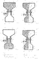
- Figs. 1A, 1B, 1C and 1D illustrate an apparatus 10 comprising a first reservoir 40 for the optically active fluid 30, a second reservoir 42 for the optically active fluid 30 and a conduit 44 between the first and second reservoirs 40, 42.
- the conduit 44 provides a route by which the optically active fluid 30 may be transferred between the first reservoir 40 and the second reservoir 42.
- a valve 50 controls the flow of the optically active fluid through the conduit 44.
- the conduit 44 is blocked when the valve 50 has a first shape 56 and the conduit is not blocked when the valve has the second shape 52.
- Transfer circuitry 20 is configured to generate electrically a first transfer gradient 22 for transferring the optically active fluid 30 between reservoirs, for example from the first reservoir 40 to the second reservoir 42 (see Fig. 1B ).
- the valve 50 is configured to control transfer of the optically active fluid 30 from the first reservoir 40 to the second reservoir 42.
- the valve 50 is closed 58 when it has the first shape 56 and the valve 50 is open 54 when it has the second shape 52 different to the first shape 56.
- Valve control circuitry 60 is configured to provide a first voltage to change the valve 50 from the first shape 56 to the second shape 52 and open 54 the valve facilitating transfer of the optically active fluid 30 from the first reservoir 40 to the second reservoir 42 along the electrically generated first transfer gradient 22 (see Fig. 1B ).
- valve 50 automatically changes from the second shape 52 to the first shape 56 and closes 58 inhibiting transfer of the optically active fluid 30 (see Fig. 1C ).
- the transfer circuitry 20 is also configured to generate electrically a second transfer gradient 24 for transferring the optically active fluid 30 from the second reservoir 42 to the first reservoir 40 (see Fig. 1D ).
- the valve 50 is configured to control transfer of the optically active fluid 30 from the second reservoir 42 to the first reservoir 40.
- the valve control circuitry 60 is configured to provide a second voltage to change the valve 50 from the first shape 56 to the second shape 52 and open 54 the valve 50 facilitating transfer of the optically active fluid 30 between reservoirs, for example, from the second reservoir 42 to the first reservoir 40 along the electrically generated second transfer gradient 24 (see Fig. 1D ).
- the first voltage and the second voltage may be the same value.
- the first voltage and the second voltage may be different values.
- valve 50 automatically changes from the second shape 52 to the first shape 56 and closes 58 inhibiting transfer of the optically active fluid 30.
- the apparatus 10 has two stable states as illustrated in Fig. 1A and Fig 1C .
- the optically active fluid 30 is retained in only the first reservoir 40 by the valve 50 which is in the first shape 56 and closed 58.
- the optically active fluid 30 is retained in only the second reservoir 42 by the valve 50 which is in the first shape 56 and closed 58.
- valve 50 is located in the conduit 44 and each of the Figs. 1A to 1D illustrate a cross sectional view of the valve 50.
- the valve blocks the conduit 44 and in Figs. 1B and 1D the valve 50, in the second shape 52, provides an open passage through the conduit 44.
- the first reservoir 40, the second reservoir 42 and the conduit 44 form a sealed system for the optically active fluid 30.
- a sealed system is a system that conserves the quality of optically active fluid 30.
- the optically active fluid 30 is therefore in only one of three places- the first reservoir 40, the second reservoir 42 and the conduit 44.
- the sealed system may be of fixed shape and volume. There are, in this example, no additional reservoirs other than the first reservoir 40 and the second reservoir 42.
- the sealed system comprises a mixture 32 of immiscible liquids.
- One or both of the immiscible liquids is an optically active fluid 30.
- a first immiscible liquid 34 is an optically active fluid 30.
- the second immiscible liquid 36 of the mixture 32 may, or may not be an optically active fluid.
- the first immiscible liquid 34 and the second immiscible liquid 36 have different optical properties and are mixed together in the same volume defined by the sealed system.
- the first immiscible liquid 34 and the second immiscible liquid 36 may have contrastingly different optical properties. For example they may have different colors, they may have different optical absorption, they may have different refractive indices. For example one of the immiscible liquids may be black, while the other of the immiscible liquids may be clear or white.
- the immiscible liquids may also have different characteristics.
- one of the immiscible liquids may be hydrophobic while the other may be hydrophilic.
- one of the immiscible liquids may have a high dielectric permittivity while the other may have a low dielectric permittivity.
- Electrowetting is a modification of the wetting properties of a surface with an applied electric field.
- the surface liquid contact angle changes due to applied potential difference.
- the generated first transfer gradient 22 and/or the generated second transfer gradient 24 may be produced using electrowetting by changing the applied electric field at the surface of the first reservoir 40 and/or at the surface of the second reservoir 42.
- the surface of the first reservoir 40 and/or the second reservoir 42 may comprise a suitable electrowetting material such as an amorphous fluoropolymer.
- the different immiscible liquids have different dielectric permittivities, then they will be subjected to different force values in the presence of the same electric field because of different Gibbs energy values, for example, associated with the capacitive (charge storage) effects of the liquids.
- One of the immiscible fluids will therefore be drawn in one direction in preference to the other immiscible fluid and will occupy one of the reservoirs. The other immiscible fluid will be displaced from that reservoir.
- valve control circuitry 60 may comprise first valve electrodes 61 associated with the conduit 44 and second valve electrodes 63 also associated with the conduit 44.
- the first valve electrodes 61 and the second valve electrodes 63 form pairs of electrodes. Each pair of electrodes comprises a first valve electrode 61 and a second valve electrode 63 which are arranged in an overlapping configuration and separated by a gap. Each pair of electrodes therefore forms a parallel capacitor. As illustrated in Figs 2A, 2B and 3A, 3B , the valve control circuitry 60 may also comprise a voltage generator circuitry 64 configured to generate a voltage 62 between the first valve electrode 61 and the second valve electrode 63 in each pair of electrodes. The electric field that is generated between the first valve electrode 61 and the second valve electrode 63 of each pair of electrodes is perpendicular to the first transfer gradient 22 and the second transfer gradient 24.
- This electric field deforms an electromechanical gel 70 to the second shape 52, opening the valve 50.
- the electromechanical gel 70 is preferentially drawn towards adjacent portions of sidewalls 46 of the conduit 44 creating a fluid passage 72 through the conduit 44 (see Figs. 2B and 3B ).
- the electromechanical gel 70 returns to its stable configuration and adopts the first shape 56, closing 58 the valve 50 (see Figs. 2A and 3A ).
- the first valve electrode 61 and the second valve electrode 63 of a pair of electrodes lie in the same plane.
- the first valve electrode 61 and the second valve electrode 63 of a pair of electrodes lie in different planes.
- the valve control circuitry 60 comprises a first pair of overlapping first and second valve electrodes 61, 63 adjacent a first sidewall 46 of the conduit 44 and a second pair of overlapping first and second valve electrodes 61, 63 adjacent a second sidewall 46 of the conduit 44, where the first and second sidewalls of the conduit are opposing across the conduit 44.
- the first pair of valve electrodes comprises a first valve electrode 61 and a second valve electrode 63 separated from the first valve electrode 61 in a direction perpendicular to the first/second transfer gradients 22/24.
- the second pair of valve electrodes comprises a first valve electrode 61 and a second valve electrode 63 separated from the first valve electrode 61 in a direction perpendicular to the first/second transfer gradients 22/24.
- the order of the first valve electrode 61 and the second valve electrode 63 for each of the pairs of electrodes is the same. However, in other examples the order may be reversed for one or both of the pairs.
- the apparatus 10 may have a maximum dimension of less than ten micrometers and the first and the second valve electrodes 61, 63 may have a maximum dimension of less than one micrometer. Of course, other dimensions are possible.
- the transfer circuitry 20 comprises a first transfer electrode 21 associated with the first reservoir 40, a second transfer electrode 23 associated with the second reservoir 42 and voltage generation circuitry 64 configured to generate a voltage 62 of a first polarity between the first and second transfer electrodes 21, 23 to generate electrically the first transfer gradient 22 and configured to generate a voltage 62 of a second polarity, opposite the first polarity, between the first and second transfer electrodes 21, 23 to generate electrically a second transfer gradient 24, opposite the first transfer gradient 22.
- Fig. 1B illustrates the generation of the first transfer gradient 22 using the first and second transfer electrodes 21, 23
- Fig. 1D illustrates the generation of the second transfer gradient 24 using the first and second transfer electrodes 21, 23.
- the transfer circuitry 20 and the valve control circuitry 60 operate independently. It is therefore possible to separate the timing of generation of the transfer gradients and the opening/closing of the valve 50 by the valve control circuitry 60. It is therefore possible for the transfer gradient generation and the valve opening to be synchronous or asynchronous.
- Figs. 4A to 4D illustrate examples of the apparatus as previously described with reference to Figs. 1A to 1D (and also Figs. 2A to 2B and 3A to 3B ), however, in this example the first valve electrodes 61 of the valve control circuitry 60 and the first transfer electrodes 21 of the transfer circuitry 20 are provided by a single first common electrode 80 and the second valve electrode 63 of the valve control circuitry 60 and the second transfer electrode 23 of the transfer circuitry 20 are provided by a single second common electrode 82. In this example, the transfer circuitry 20 and the valve control circuitry 60 are interconnected and a single voltage generation circuitry may be used for both the transfer circuitry 20 and the valve control circuitry 60.
- Figs. 5A and 5B illustrate operation of the transfer circuitry 20 and the valve control circuitry 60 of the apparatus 10 illustrated in Figs. 4A to 4D .
- a first voltage V1 is applied to the first common electrode 80 and a second voltage V2 is applied to the second common electrode 82. Both the first voltage V1 and the second voltage V2 are time variable. When both the first voltage V1 and the second voltage V2 have the same value there is zero potential difference between the first common electrode 80 and the second common electrode 82.
- the potential difference between the first voltage V1 and the second voltage V2 has a first polarity
- the first transfer gradient 22 is generated and the valve 50 adopts the second shape 52 and opens 54 as illustrated in Fig. 4B .
- the potential difference between the first voltage V1 and the second voltage V2 has a second polarity, opposite the first polarity, the second transfer gradient 24 is generated and the valve 50 adopts the second shape 52 and opens 54.
- Fig. 5A illustrates the time variation of the first voltage V1 and the second voltage V2 over four different sequential time periods A, B, C, D of equal length. Each of the time periods relates to a respective one of the Figs. 4A, 4B, 4C and 4D.
- Fig. 5B illustrates the potential difference (V1-V2) for each of the time sequences A, B, C, D.
- the first voltage V1 and the second voltage V2 are both high and the potential difference ⁇ V is low. There is no transfer gradient generated and the valve 50 is closed 58.
- the first voltage V1 is high and the second voltage V2 is low.
- the potential difference ⁇ V is large and positive and the first transfer gradient 22 is generated and the valve 50 is open 54.
- the first voltage V1 is high and the second voltage V2 is high and the potential difference is low.
- the fourth time period D the first voltage V1 is low and the second voltage V2 is high.
- the potential difference ⁇ V is large and negative and the second transfer gradient 24 is generated and the valve 50 is open 54.
- valve 50 is a non-polar component and it is in an open configuration when it receives a positive potential difference and also when it received a negative potential difference.
- Fig. 6A illustrates an example of a display system 100 comprising a plurality of apparatus 10 as previously described.
- the apparatus 10 are arranged in a regular array 110 comprising equally spaced rows and columns.
- column drive lines 114 are interconnected to the first common electrode 80 of each of the apparatus 10 in a single column and row drive lines 112 are interconnected to each of the second common electrodes 82 of the apparatus 10 in a single row. It is therefore possible to generate a potential difference between the first common electrode 80 and the second common electrode 82 of a particular apparatus 10 by driving the row drive line 112 and the column drive line 114 associated with that apparatus 10.
- Fig. 6B illustrates a time sequence for a particular apparatus 10 in the display system 100.
- the column waveform illustrates the voltage provided to the column drive line 114 and the row waveform illustrates the voltage provided to the row drive line 112.
- a differential voltage of a first polarity is applied between the row drive line 112 and the column drive line 114 of an apparatus 10 that the optically active fluid 30 moves from the first reservoir 40 to the second reservoir 42 via an open valve 50 along the first transfer gradient 22.
- the optically active fluid 30 moves from the second reservoir 42 to the first reservoir 40 via an open 54 valve 50 along the second transfer gradient 24.
- the valve 50 is closed 58 and the optically active fluid does not move between reservoirs.
- Fig. 6C illustrates the display system 100 of Fig. 6A , in which for each apparatus 10 one of the first reservoir 40 and the second reservoir 42 is obscured using an opaque mask 120.
- each apparatus 10 has the same one of the first and second reservoirs obscured.
- the first reservoirs 40 are visible and these provide pixels or sub-pixels 130 of the display system 100.
- the optical characteristics, such as color, of a particular pixel or sub-pixel 130 may be controlled by moving the optically active fluid 30 from the first reservoir 40 to the second reservoir 42 and from the second reservoir 42 to the first reservoir 40.
Landscapes
- Engineering & Computer Science (AREA)
- General Engineering & Computer Science (AREA)
- Mechanical Engineering (AREA)
- Physics & Mathematics (AREA)
- Chemical & Material Sciences (AREA)
- Dispersion Chemistry (AREA)
- General Physics & Mathematics (AREA)
- Optics & Photonics (AREA)
- Computer Hardware Design (AREA)
- Theoretical Computer Science (AREA)
- Mechanical Light Control Or Optical Switches (AREA)
Claims (15)
- Appareil (10) comprenant :un circuit de transfert (20) configuré pour générer électriquement un premier gradient de transfert (22) pour transférer un fluide optiquement actif (30) d'un premier réservoir (40) à un second réservoir (42) ;une soupape (50) configurée pour contrôler le transfert du fluide optiquement actif (30) du premier réservoir (40) au second réservoir (42), dans lequel la soupape (50) est fermée (58) lorsqu'elle a une première forme (56) et la soupape (50) est ouverte (54) lorsqu'elle a une seconde forme (52) différente de la première forme (56) ; etle circuit de commande de soupape (60) configuré pour fournir une tension afin de faire passer la soupape (50) de la première forme (56) à la seconde forme (52) et ouvrir (54) la soupape (50) facilitant le transfert du fluide optiquement actif (30) du premier réservoir (40) au second réservoir (42) le long du premier gradient de transfert (22) électriquement généré.
- Appareil (10) selon la revendication 1, dans lequel le circuit de transfert (20) est configuré pour générer électriquement un second gradient de transfert (24) pour transférer le fluide optiquement actif (30) du second réservoir (42) au premier réservoir (40), dans lequel la soupape (50) est configurée pour contrôler le transfert du fluide optiquement actif (30) du second réservoir (42) au premier réservoir (40), et dans lequel le circuit de commande de soupape (60) est configuré pour fournir une tension afin de faire passer la soupape (50) de la première forme (56) à la seconde forme (52) et ouvrir (54) la soupape (50), facilitant le transfert du fluide optiquement actif (30) du second réservoir (42) au premier réservoir (40) le long du second gradient de transfert (24) électriquement généré.
- Appareil (10) selon la revendication 1 ou 2, dans lequel la soupape (50) est configurée pour avoir la première forme (56) par défaut.
- Appareil (10) selon l'une quelconque des revendications précédentes, dans lequel la soupape (50) comprend un gel électromécanique.
- Appareil (10) selon la revendication 4, dans lequel le circuit de commande de soupape (60) est configuré pour fournir une tension, afin d'ouvrir la soupape (50), dans une direction perpendiculaire au premier gradient de transfert (22) pour déformer le gel électromécanique.
- Appareil (10) selon l'une quelconque des revendications précédentes, comprenant :
un premier réservoir (40) pour le fluide optiquement actif (30), un second réservoir (42) pour le fluide optiquement actif (30), un conduit (44) entre les premier (40) et second (42) réservoirs, dans lequel la soupape (50) contrôle l'écoulement du fluide optiquement actif (30) à travers le conduit (44), dans lequel le conduit (44) est bloqué lorsque la soupape (50) a la première forme (56) et dans lequel le conduit (44) n'est pas bloqué lorsque la soupape (50) a la seconde forme (52). - Appareil (10) selon la revendication 6, dans lequel le circuit de transfert (20) comprend une première électrode de transfert (21) associée au premier réservoir (40), une seconde électrode de transfert (23) associée au second réservoir (42) et un circuit configuré pour générer une tension d'une première polarité entre les première et seconde électrodes (21, 23) afin de générer électriquement le premier gradient de transfert (22) et configuré pour générer une tension d'une seconde polarité, opposée à la première polarité, entre les première et seconde électrodes (21, 23) afin de générer électriquement un second gradient de transfert (24), opposé au premier gradient de transfert (22).
- Appareil (10) selon la revendication 6 ou 7, dans lequel le circuit de commande de soupape comprend au moins une première électrode de soupape (61) associée au conduit (44), au moins une seconde électrode de soupape (63) respective associée au conduit (44) et le circuit configuré pour générer une tension entre les première et seconde électrodes de soupape (61, 63) perpendiculaires au premier gradient de transfert (22) afin de déformer un gel électromécanique dans la seconde forme (52), dans lequel le gel électromécanique est de préférence utilisé de manière adjacente à au moins des parties des parois latérales (46) du conduit (44), créant un passage de fluide à travers le conduit (44).
- Appareil (10) selon la revendication 6, 7 ou 8, dans lequel le circuit de commande de soupape comprend au moins une première paire d'électrodes de soupape (61, 63) en chevauchement, adjacente à une première paroi latérale du conduit (44), dans lequel la première paire d'électrodes de soupape (61, 63) comprend une première électrode de soupape (61) et une seconde électrode de soupape (63) séparée de la première électrode de soupape (61) dans une direction perpendiculaire au premier gradient de transfert (22).
- Appareil (10) selon la revendication 6, 7 ou 8, dans lequel le premier réservoir (40), le second réservoir (42) et le conduit (44) forment un système étanche de forme et de volume fixe pour le fluide optiquement actif (30) sans réservoirs supplémentaires.
- Appareil (10) selon l'une quelconque des revendications précédentes, dans lequel le circuit de transfert (20) et le circuit de commande de soupape (60) fonctionnent indépendamment.
- Appareil (10) selon l'une quelconque des revendications précédentes, dans lequel le circuit de transfert (20) et le circuit de commande de soupape (60) sont fournis par le circuit commun.
- Appareil (10) selon l'une quelconque des revendications précédentes, dans lequel le fluide optiquement actif (30) comprend un ou plusieurs d'une pluralité de liquides non miscibles ayant différentes propriétés optiques qui partagent le même volume.
- Système d'affichage (100) comprenant une pluralité d'appareils (10) selon l'une quelconque des revendications précédentes, agencés sur un réseau régulier de rangées et de colonne, dans lequel chaque appareil (10) a un premier réservoir (40) exposé et un second réservoir (42) dissimulé, les premiers réservoirs (40) fournissant des pixels ou des pixels secondaires (130) du système d'affichage (100).
- Procédé comprenant les étapes consistant à :fournir une ou plusieurs tensions afin de générer un premier gradient de transfert (22) pour transférer un fluide optiquement actif (30) d'un premier réservoir (40) à un second réservoir (42) et pour ouvrir une soupape (50) afin de faciliter le transfert du fluide optiquement actif (30) du premier réservoir (40) au second réservoir (42) le long du premier gradient de transfert (22) électriquement généré,dans lequel la soupape (50) est fermée (58) lorsqu'elle a une première forme (56) et la soupape (50) est ouverte (54) lorsqu'elle a une seconde forme (52) différente de la première forme (56) ;supprimer les une ou plusieurs tensions afin de supprimer le premier gradient de transfert (22) et fermer (58) la soupape (50) .
Priority Applications (4)
| Application Number | Priority Date | Filing Date | Title |
|---|---|---|---|
| EP15171083.7A EP3104208B1 (fr) | 2015-06-09 | 2015-06-09 | Circuit électronique pour une soupape pour le transfert d'un fluide optiquement actif d'un premier réservoir vers un second réservoir |
| CN201680033110.5A CN107690544B (zh) | 2015-06-09 | 2016-05-31 | 控制光学活性流体从第一转移到第二储存器的装置和方法 |
| PCT/FI2016/050379 WO2016198736A1 (fr) | 2015-06-09 | 2016-05-31 | Circuit électronique pour une soupape à des fins de transfert d'un fluide optiquement actif d'un premier réservoir à un deuxième réservoir |
| US15/578,283 US10359622B2 (en) | 2015-06-09 | 2016-05-31 | Electronic circuitry for a valve for the transfer of an optically-active fluid from a first to a second reservoir |
Applications Claiming Priority (1)
| Application Number | Priority Date | Filing Date | Title |
|---|---|---|---|
| EP15171083.7A EP3104208B1 (fr) | 2015-06-09 | 2015-06-09 | Circuit électronique pour une soupape pour le transfert d'un fluide optiquement actif d'un premier réservoir vers un second réservoir |
Publications (2)
| Publication Number | Publication Date |
|---|---|
| EP3104208A1 EP3104208A1 (fr) | 2016-12-14 |
| EP3104208B1 true EP3104208B1 (fr) | 2022-08-24 |
Family
ID=53442497
Family Applications (1)
| Application Number | Title | Priority Date | Filing Date |
|---|---|---|---|
| EP15171083.7A Active EP3104208B1 (fr) | 2015-06-09 | 2015-06-09 | Circuit électronique pour une soupape pour le transfert d'un fluide optiquement actif d'un premier réservoir vers un second réservoir |
Country Status (4)
| Country | Link |
|---|---|
| US (1) | US10359622B2 (fr) |
| EP (1) | EP3104208B1 (fr) |
| CN (1) | CN107690544B (fr) |
| WO (1) | WO2016198736A1 (fr) |
Family Cites Families (9)
| Publication number | Priority date | Publication date | Assignee | Title |
|---|---|---|---|---|
| CA2341896A1 (fr) * | 1998-08-28 | 2000-03-09 | Febit Ferrarius Biotechnology Gmbh | Support pour un procede de determination d'analyte et procede de fabrication du support |
| US6685442B2 (en) * | 2002-02-20 | 2004-02-03 | Sandia National Laboratories | Actuator device utilizing a conductive polymer gel |
| US8056881B2 (en) * | 2004-10-13 | 2011-11-15 | University Of Virginia Patent Foundation | Electrostatic actuation for management of flow in micro-total analysis systems (μ-TAS) and related method thereof |
| EP1835213B1 (fr) | 2004-12-17 | 2012-03-07 | Brother Kogyo Kabushiki Kaisha | Soupape et actionneur employant un phenomene d'humidification capillaire electrique |
| US7382544B2 (en) * | 2006-02-10 | 2008-06-03 | Honeywell International Inc. | Devices and related methods for light distribution |
| JP5338036B2 (ja) | 2007-04-18 | 2013-11-13 | 藤倉化成株式会社 | 電気レオロジーゲル素子および電気レオロジーゲルの製造方法 |
| JP5874353B2 (ja) | 2011-11-30 | 2016-03-02 | セントラル硝子株式会社 | フルオロアルカンスルホン酸無水物の製造方法 |
| WO2013087804A1 (fr) * | 2011-12-15 | 2013-06-20 | General Electric Company | Perfectionnements apportés et se rapportant à des pompes électro-osmotiques |
| US9335539B2 (en) * | 2012-01-23 | 2016-05-10 | President And Fellows Of Harvard College | Pixel device and display using liquid ink and elastomers |
-
2015
- 2015-06-09 EP EP15171083.7A patent/EP3104208B1/fr active Active
-
2016
- 2016-05-31 CN CN201680033110.5A patent/CN107690544B/zh active Active
- 2016-05-31 US US15/578,283 patent/US10359622B2/en active Active
- 2016-05-31 WO PCT/FI2016/050379 patent/WO2016198736A1/fr not_active Ceased
Also Published As
| Publication number | Publication date |
|---|---|
| CN107690544A (zh) | 2018-02-13 |
| EP3104208A1 (fr) | 2016-12-14 |
| US10359622B2 (en) | 2019-07-23 |
| US20180143423A1 (en) | 2018-05-24 |
| WO2016198736A1 (fr) | 2016-12-15 |
| CN107690544B (zh) | 2020-01-31 |
Similar Documents
| Publication | Publication Date | Title |
|---|---|---|
| US8287708B2 (en) | Microfluidic system and method for creating an encapsulated droplet with a removable shell | |
| US8031168B2 (en) | Display device having an electrode partially covering a picture element | |
| KR101211199B1 (ko) | 광학 장치 | |
| CN100576014C (zh) | 显示装置 | |
| EP3853662B1 (fr) | Appareil d'electromouillage sur dielectrique à électrodes hexagonales et triangulaires | |
| WO2003023510A1 (fr) | Affichage a electrophorese a electrodes de commande dans le plan | |
| TWI434259B (zh) | 電泳裝置與其控制方法 | |
| JP2022111178A (ja) | 静電気作動装置を備えた眼鏡 | |
| CN102177464B (zh) | 移动粒子显示设备 | |
| EP3104208B1 (fr) | Circuit électronique pour une soupape pour le transfert d'un fluide optiquement actif d'un premier réservoir vers un second réservoir | |
| US9201247B2 (en) | Electrically switchable light-modulating cell with via for image display apparatus | |
| US8031408B2 (en) | Fluid displacement mechanism | |
| US20120013973A1 (en) | Electro-optical display | |
| US20090134009A1 (en) | Device for controlling the displacement of a volume of liquid between two or more solid substrates and displacement method | |
| Wu et al. | Electrostatic droplet manipulation using electret as a voltage source | |
| HK40039648B (zh) | 具有六角形和三角形电极的背板 | |
| HK40039648A (en) | Backplanes with hexagonal and triangular electrodes | |
| Dannenberg et al. | On The Modelling of Electrowetting in COMSOL MultiPhysics |
Legal Events
| Date | Code | Title | Description |
|---|---|---|---|
| PUAI | Public reference made under article 153(3) epc to a published international application that has entered the european phase |
Free format text: ORIGINAL CODE: 0009012 |
|
| STAA | Information on the status of an ep patent application or granted ep patent |
Free format text: STATUS: THE APPLICATION HAS BEEN PUBLISHED |
|
| AK | Designated contracting states |
Kind code of ref document: A1 Designated state(s): AL AT BE BG CH CY CZ DE DK EE ES FI FR GB GR HR HU IE IS IT LI LT LU LV MC MK MT NL NO PL PT RO RS SE SI SK SM TR |
|
| AX | Request for extension of the european patent |
Extension state: BA ME |
|
| STAA | Information on the status of an ep patent application or granted ep patent |
Free format text: STATUS: REQUEST FOR EXAMINATION WAS MADE |
|
| 17P | Request for examination filed |
Effective date: 20170609 |
|
| RBV | Designated contracting states (corrected) |
Designated state(s): AL AT BE BG CH CY CZ DE DK EE ES FI FR GB GR HR HU IE IS IT LI LT LU LV MC MK MT NL NO PL PT RO RS SE SI SK SM TR |
|
| RAP1 | Party data changed (applicant data changed or rights of an application transferred) |
Owner name: NOKIA TECHNOLOGIES OY |
|
| STAA | Information on the status of an ep patent application or granted ep patent |
Free format text: STATUS: EXAMINATION IS IN PROGRESS |
|
| 17Q | First examination report despatched |
Effective date: 20200224 |
|
| GRAP | Despatch of communication of intention to grant a patent |
Free format text: ORIGINAL CODE: EPIDOSNIGR1 |
|
| STAA | Information on the status of an ep patent application or granted ep patent |
Free format text: STATUS: GRANT OF PATENT IS INTENDED |
|
| RIC1 | Information provided on ipc code assigned before grant |
Ipc: G09G 3/34 20060101ALI20210826BHEP Ipc: F16K 99/00 20060101ALI20210826BHEP Ipc: F16K 31/02 20060101ALI20210826BHEP Ipc: G02B 26/00 20060101AFI20210826BHEP |
|
| INTG | Intention to grant announced |
Effective date: 20210923 |
|
| GRAJ | Information related to disapproval of communication of intention to grant by the applicant or resumption of examination proceedings by the epo deleted |
Free format text: ORIGINAL CODE: EPIDOSDIGR1 |
|
| STAA | Information on the status of an ep patent application or granted ep patent |
Free format text: STATUS: EXAMINATION IS IN PROGRESS |
|
| INTC | Intention to grant announced (deleted) | ||
| GRAP | Despatch of communication of intention to grant a patent |
Free format text: ORIGINAL CODE: EPIDOSNIGR1 |
|
| STAA | Information on the status of an ep patent application or granted ep patent |
Free format text: STATUS: GRANT OF PATENT IS INTENDED |
|
| INTG | Intention to grant announced |
Effective date: 20220317 |
|
| GRAS | Grant fee paid |
Free format text: ORIGINAL CODE: EPIDOSNIGR3 |
|
| GRAA | (expected) grant |
Free format text: ORIGINAL CODE: 0009210 |
|
| STAA | Information on the status of an ep patent application or granted ep patent |
Free format text: STATUS: THE PATENT HAS BEEN GRANTED |
|
| AK | Designated contracting states |
Kind code of ref document: B1 Designated state(s): AL AT BE BG CH CY CZ DE DK EE ES FI FR GB GR HR HU IE IS IT LI LT LU LV MC MK MT NL NO PL PT RO RS SE SI SK SM TR |
|
| REG | Reference to a national code |
Ref country code: CH Ref legal event code: EP |
|
| REG | Reference to a national code |
Ref country code: DE Ref legal event code: R096 Ref document number: 602015080448 Country of ref document: DE |
|
| REG | Reference to a national code |
Ref country code: IE Ref legal event code: FG4D |
|
| REG | Reference to a national code |
Ref country code: AT Ref legal event code: REF Ref document number: 1514049 Country of ref document: AT Kind code of ref document: T Effective date: 20220915 |
|
| REG | Reference to a national code |
Ref country code: LT Ref legal event code: MG9D |
|
| REG | Reference to a national code |
Ref country code: NL Ref legal event code: MP Effective date: 20220824 |
|
| PG25 | Lapsed in a contracting state [announced via postgrant information from national office to epo] |
Ref country code: SE Free format text: LAPSE BECAUSE OF FAILURE TO SUBMIT A TRANSLATION OF THE DESCRIPTION OR TO PAY THE FEE WITHIN THE PRESCRIBED TIME-LIMIT Effective date: 20220824 Ref country code: RS Free format text: LAPSE BECAUSE OF FAILURE TO SUBMIT A TRANSLATION OF THE DESCRIPTION OR TO PAY THE FEE WITHIN THE PRESCRIBED TIME-LIMIT Effective date: 20220824 Ref country code: PT Free format text: LAPSE BECAUSE OF FAILURE TO SUBMIT A TRANSLATION OF THE DESCRIPTION OR TO PAY THE FEE WITHIN THE PRESCRIBED TIME-LIMIT Effective date: 20221226 Ref country code: NO Free format text: LAPSE BECAUSE OF FAILURE TO SUBMIT A TRANSLATION OF THE DESCRIPTION OR TO PAY THE FEE WITHIN THE PRESCRIBED TIME-LIMIT Effective date: 20221124 Ref country code: NL Free format text: LAPSE BECAUSE OF FAILURE TO SUBMIT A TRANSLATION OF THE DESCRIPTION OR TO PAY THE FEE WITHIN THE PRESCRIBED TIME-LIMIT Effective date: 20220824 Ref country code: LV Free format text: LAPSE BECAUSE OF FAILURE TO SUBMIT A TRANSLATION OF THE DESCRIPTION OR TO PAY THE FEE WITHIN THE PRESCRIBED TIME-LIMIT Effective date: 20220824 Ref country code: LT Free format text: LAPSE BECAUSE OF FAILURE TO SUBMIT A TRANSLATION OF THE DESCRIPTION OR TO PAY THE FEE WITHIN THE PRESCRIBED TIME-LIMIT Effective date: 20220824 Ref country code: FI Free format text: LAPSE BECAUSE OF FAILURE TO SUBMIT A TRANSLATION OF THE DESCRIPTION OR TO PAY THE FEE WITHIN THE PRESCRIBED TIME-LIMIT Effective date: 20220824 Ref country code: ES Free format text: LAPSE BECAUSE OF FAILURE TO SUBMIT A TRANSLATION OF THE DESCRIPTION OR TO PAY THE FEE WITHIN THE PRESCRIBED TIME-LIMIT Effective date: 20220824 |
|
| REG | Reference to a national code |
Ref country code: AT Ref legal event code: MK05 Ref document number: 1514049 Country of ref document: AT Kind code of ref document: T Effective date: 20220824 |
|
| PG25 | Lapsed in a contracting state [announced via postgrant information from national office to epo] |
Ref country code: PL Free format text: LAPSE BECAUSE OF FAILURE TO SUBMIT A TRANSLATION OF THE DESCRIPTION OR TO PAY THE FEE WITHIN THE PRESCRIBED TIME-LIMIT Effective date: 20220824 Ref country code: IS Free format text: LAPSE BECAUSE OF FAILURE TO SUBMIT A TRANSLATION OF THE DESCRIPTION OR TO PAY THE FEE WITHIN THE PRESCRIBED TIME-LIMIT Effective date: 20221224 Ref country code: HR Free format text: LAPSE BECAUSE OF FAILURE TO SUBMIT A TRANSLATION OF THE DESCRIPTION OR TO PAY THE FEE WITHIN THE PRESCRIBED TIME-LIMIT Effective date: 20220824 Ref country code: GR Free format text: LAPSE BECAUSE OF FAILURE TO SUBMIT A TRANSLATION OF THE DESCRIPTION OR TO PAY THE FEE WITHIN THE PRESCRIBED TIME-LIMIT Effective date: 20221125 |
|
| PG25 | Lapsed in a contracting state [announced via postgrant information from national office to epo] |
Ref country code: SM Free format text: LAPSE BECAUSE OF FAILURE TO SUBMIT A TRANSLATION OF THE DESCRIPTION OR TO PAY THE FEE WITHIN THE PRESCRIBED TIME-LIMIT Effective date: 20220824 Ref country code: RO Free format text: LAPSE BECAUSE OF FAILURE TO SUBMIT A TRANSLATION OF THE DESCRIPTION OR TO PAY THE FEE WITHIN THE PRESCRIBED TIME-LIMIT Effective date: 20220824 Ref country code: DK Free format text: LAPSE BECAUSE OF FAILURE TO SUBMIT A TRANSLATION OF THE DESCRIPTION OR TO PAY THE FEE WITHIN THE PRESCRIBED TIME-LIMIT Effective date: 20220824 Ref country code: CZ Free format text: LAPSE BECAUSE OF FAILURE TO SUBMIT A TRANSLATION OF THE DESCRIPTION OR TO PAY THE FEE WITHIN THE PRESCRIBED TIME-LIMIT Effective date: 20220824 Ref country code: AT Free format text: LAPSE BECAUSE OF FAILURE TO SUBMIT A TRANSLATION OF THE DESCRIPTION OR TO PAY THE FEE WITHIN THE PRESCRIBED TIME-LIMIT Effective date: 20220824 |
|
| REG | Reference to a national code |
Ref country code: DE Ref legal event code: R097 Ref document number: 602015080448 Country of ref document: DE |
|
| PG25 | Lapsed in a contracting state [announced via postgrant information from national office to epo] |
Ref country code: SK Free format text: LAPSE BECAUSE OF FAILURE TO SUBMIT A TRANSLATION OF THE DESCRIPTION OR TO PAY THE FEE WITHIN THE PRESCRIBED TIME-LIMIT Effective date: 20220824 Ref country code: EE Free format text: LAPSE BECAUSE OF FAILURE TO SUBMIT A TRANSLATION OF THE DESCRIPTION OR TO PAY THE FEE WITHIN THE PRESCRIBED TIME-LIMIT Effective date: 20220824 |
|
| PG25 | Lapsed in a contracting state [announced via postgrant information from national office to epo] |
Ref country code: AL Free format text: LAPSE BECAUSE OF FAILURE TO SUBMIT A TRANSLATION OF THE DESCRIPTION OR TO PAY THE FEE WITHIN THE PRESCRIBED TIME-LIMIT Effective date: 20220824 |
|
| PLBE | No opposition filed within time limit |
Free format text: ORIGINAL CODE: 0009261 |
|
| STAA | Information on the status of an ep patent application or granted ep patent |
Free format text: STATUS: NO OPPOSITION FILED WITHIN TIME LIMIT |
|
| 26N | No opposition filed |
Effective date: 20230525 |
|
| PG25 | Lapsed in a contracting state [announced via postgrant information from national office to epo] |
Ref country code: SI Free format text: LAPSE BECAUSE OF FAILURE TO SUBMIT A TRANSLATION OF THE DESCRIPTION OR TO PAY THE FEE WITHIN THE PRESCRIBED TIME-LIMIT Effective date: 20220824 |
|
| PG25 | Lapsed in a contracting state [announced via postgrant information from national office to epo] |
Ref country code: MC Free format text: LAPSE BECAUSE OF FAILURE TO SUBMIT A TRANSLATION OF THE DESCRIPTION OR TO PAY THE FEE WITHIN THE PRESCRIBED TIME-LIMIT Effective date: 20220824 |
|
| PG25 | Lapsed in a contracting state [announced via postgrant information from national office to epo] |
Ref country code: MC Free format text: LAPSE BECAUSE OF FAILURE TO SUBMIT A TRANSLATION OF THE DESCRIPTION OR TO PAY THE FEE WITHIN THE PRESCRIBED TIME-LIMIT Effective date: 20220824 |
|
| REG | Reference to a national code |
Ref country code: CH Ref legal event code: PL |
|
| REG | Reference to a national code |
Ref country code: BE Ref legal event code: MM Effective date: 20230630 |
|
| GBPC | Gb: european patent ceased through non-payment of renewal fee |
Effective date: 20230609 |
|
| PG25 | Lapsed in a contracting state [announced via postgrant information from national office to epo] |
Ref country code: LU Free format text: LAPSE BECAUSE OF NON-PAYMENT OF DUE FEES Effective date: 20230609 |
|
| REG | Reference to a national code |
Ref country code: IE Ref legal event code: MM4A |
|
| PG25 | Lapsed in a contracting state [announced via postgrant information from national office to epo] |
Ref country code: LU Free format text: LAPSE BECAUSE OF NON-PAYMENT OF DUE FEES Effective date: 20230609 |
|
| PG25 | Lapsed in a contracting state [announced via postgrant information from national office to epo] |
Ref country code: IE Free format text: LAPSE BECAUSE OF NON-PAYMENT OF DUE FEES Effective date: 20230609 |
|
| PG25 | Lapsed in a contracting state [announced via postgrant information from national office to epo] |
Ref country code: IE Free format text: LAPSE BECAUSE OF NON-PAYMENT OF DUE FEES Effective date: 20230609 Ref country code: GB Free format text: LAPSE BECAUSE OF NON-PAYMENT OF DUE FEES Effective date: 20230609 Ref country code: CH Free format text: LAPSE BECAUSE OF NON-PAYMENT OF DUE FEES Effective date: 20230630 |
|
| PG25 | Lapsed in a contracting state [announced via postgrant information from national office to epo] |
Ref country code: IT Free format text: LAPSE BECAUSE OF FAILURE TO SUBMIT A TRANSLATION OF THE DESCRIPTION OR TO PAY THE FEE WITHIN THE PRESCRIBED TIME-LIMIT Effective date: 20220824 Ref country code: FR Free format text: LAPSE BECAUSE OF NON-PAYMENT OF DUE FEES Effective date: 20230630 Ref country code: BE Free format text: LAPSE BECAUSE OF NON-PAYMENT OF DUE FEES Effective date: 20230630 |
|
| PG25 | Lapsed in a contracting state [announced via postgrant information from national office to epo] |
Ref country code: BG Free format text: LAPSE BECAUSE OF FAILURE TO SUBMIT A TRANSLATION OF THE DESCRIPTION OR TO PAY THE FEE WITHIN THE PRESCRIBED TIME-LIMIT Effective date: 20220824 |
|
| PG25 | Lapsed in a contracting state [announced via postgrant information from national office to epo] |
Ref country code: BG Free format text: LAPSE BECAUSE OF FAILURE TO SUBMIT A TRANSLATION OF THE DESCRIPTION OR TO PAY THE FEE WITHIN THE PRESCRIBED TIME-LIMIT Effective date: 20220824 |
|
| PGFP | Annual fee paid to national office [announced via postgrant information from national office to epo] |
Ref country code: DE Payment date: 20250429 Year of fee payment: 11 |
|
| PG25 | Lapsed in a contracting state [announced via postgrant information from national office to epo] |
Ref country code: CY Free format text: LAPSE BECAUSE OF FAILURE TO SUBMIT A TRANSLATION OF THE DESCRIPTION OR TO PAY THE FEE WITHIN THE PRESCRIBED TIME-LIMIT; INVALID AB INITIO Effective date: 20150609 |
|
| PG25 | Lapsed in a contracting state [announced via postgrant information from national office to epo] |
Ref country code: HU Free format text: LAPSE BECAUSE OF FAILURE TO SUBMIT A TRANSLATION OF THE DESCRIPTION OR TO PAY THE FEE WITHIN THE PRESCRIBED TIME-LIMIT; INVALID AB INITIO Effective date: 20150609 |
|
| PG25 | Lapsed in a contracting state [announced via postgrant information from national office to epo] |
Ref country code: TR Free format text: LAPSE BECAUSE OF FAILURE TO SUBMIT A TRANSLATION OF THE DESCRIPTION OR TO PAY THE FEE WITHIN THE PRESCRIBED TIME-LIMIT Effective date: 20220824 |