EP3104221A1 - Projecteur et procédé d'affichage d'image - Google Patents
Projecteur et procédé d'affichage d'image Download PDFInfo
- Publication number
- EP3104221A1 EP3104221A1 EP14882106.9A EP14882106A EP3104221A1 EP 3104221 A1 EP3104221 A1 EP 3104221A1 EP 14882106 A EP14882106 A EP 14882106A EP 3104221 A1 EP3104221 A1 EP 3104221A1
- Authority
- EP
- European Patent Office
- Prior art keywords
- image
- pixel
- images
- area
- dmd
- Prior art date
- Legal status (The legal status is an assumption and is not a legal conclusion. Google has not performed a legal analysis and makes no representation as to the accuracy of the status listed.)
- Withdrawn
Links
- 238000000034 method Methods 0.000 title claims description 32
- 239000004973 liquid crystal related substance Substances 0.000 description 21
- 230000003287 optical effect Effects 0.000 description 18
- 230000010287 polarization Effects 0.000 description 16
- 238000010586 diagram Methods 0.000 description 13
- 230000004304 visual acuity Effects 0.000 description 11
- CNQCVBJFEGMYDW-UHFFFAOYSA-N lawrencium atom Chemical compound [Lr] CNQCVBJFEGMYDW-UHFFFAOYSA-N 0.000 description 8
- 239000010453 quartz Substances 0.000 description 7
- VYPSYNLAJGMNEJ-UHFFFAOYSA-N silicon dioxide Inorganic materials O=[Si]=O VYPSYNLAJGMNEJ-UHFFFAOYSA-N 0.000 description 7
- 230000004075 alteration Effects 0.000 description 5
- 230000008859 change Effects 0.000 description 4
- 230000000694 effects Effects 0.000 description 4
- 238000005286 illumination Methods 0.000 description 4
- 206010047571 Visual impairment Diseases 0.000 description 2
- 230000002159 abnormal effect Effects 0.000 description 2
- 230000015556 catabolic process Effects 0.000 description 2
- 239000003086 colorant Substances 0.000 description 2
- 238000012937 correction Methods 0.000 description 2
- 238000006731 degradation reaction Methods 0.000 description 2
- 238000005516 engineering process Methods 0.000 description 2
- 210000000887 face Anatomy 0.000 description 2
- 230000004907 flux Effects 0.000 description 2
- 230000008569 process Effects 0.000 description 2
- XUIMIQQOPSSXEZ-UHFFFAOYSA-N Silicon Chemical compound [Si] XUIMIQQOPSSXEZ-UHFFFAOYSA-N 0.000 description 1
- 230000003466 anti-cipated effect Effects 0.000 description 1
- 238000004364 calculation method Methods 0.000 description 1
- 230000007812 deficiency Effects 0.000 description 1
- 238000013461 design Methods 0.000 description 1
- 230000006866 deterioration Effects 0.000 description 1
- 230000009982 effect on human Effects 0.000 description 1
- 238000004519 manufacturing process Methods 0.000 description 1
- 238000012986 modification Methods 0.000 description 1
- 230000004048 modification Effects 0.000 description 1
- 230000002093 peripheral effect Effects 0.000 description 1
- 229910021420 polycrystalline silicon Inorganic materials 0.000 description 1
- 229920005591 polysilicon Polymers 0.000 description 1
- 230000001105 regulatory effect Effects 0.000 description 1
- 229910052710 silicon Inorganic materials 0.000 description 1
- 239000010703 silicon Substances 0.000 description 1
- 238000009751 slip forming Methods 0.000 description 1
- 239000010409 thin film Substances 0.000 description 1
- 238000012546 transfer Methods 0.000 description 1
Images



Classifications
-
- H—ELECTRICITY
- H04—ELECTRIC COMMUNICATION TECHNIQUE
- H04N—PICTORIAL COMMUNICATION, e.g. TELEVISION
- H04N9/00—Details of colour television systems
- H04N9/12—Picture reproducers
- H04N9/31—Projection devices for colour picture display, e.g. using electronic spatial light modulators [ESLM]
- H04N9/3102—Projection devices for colour picture display, e.g. using electronic spatial light modulators [ESLM] using two-dimensional electronic spatial light modulators
- H04N9/3111—Projection devices for colour picture display, e.g. using electronic spatial light modulators [ESLM] using two-dimensional electronic spatial light modulators for displaying the colours sequentially, e.g. by using sequentially activated light sources
-
- H—ELECTRICITY
- H04—ELECTRIC COMMUNICATION TECHNIQUE
- H04N—PICTORIAL COMMUNICATION, e.g. TELEVISION
- H04N9/00—Details of colour television systems
- H04N9/12—Picture reproducers
- H04N9/31—Projection devices for colour picture display, e.g. using electronic spatial light modulators [ESLM]
- H04N9/3102—Projection devices for colour picture display, e.g. using electronic spatial light modulators [ESLM] using two-dimensional electronic spatial light modulators
- H04N9/3105—Projection devices for colour picture display, e.g. using electronic spatial light modulators [ESLM] using two-dimensional electronic spatial light modulators for displaying all colours simultaneously, e.g. by using two or more electronic spatial light modulators
- H04N9/3108—Projection devices for colour picture display, e.g. using electronic spatial light modulators [ESLM] using two-dimensional electronic spatial light modulators for displaying all colours simultaneously, e.g. by using two or more electronic spatial light modulators by using a single electronic spatial light modulator
-
- G—PHYSICS
- G09—EDUCATION; CRYPTOGRAPHY; DISPLAY; ADVERTISING; SEALS
- G09G—ARRANGEMENTS OR CIRCUITS FOR CONTROL OF INDICATING DEVICES USING STATIC MEANS TO PRESENT VARIABLE INFORMATION
- G09G3/00—Control arrangements or circuits, of interest only in connection with visual indicators other than cathode-ray tubes
- G09G3/001—Control arrangements or circuits, of interest only in connection with visual indicators other than cathode-ray tubes using specific devices not provided for in groups G09G3/02 - G09G3/36, e.g. using an intermediate record carrier such as a film slide; Projection systems; Display of non-alphanumerical information, solely or in combination with alphanumerical information, e.g. digital display on projected diapositive as background
- G09G3/002—Control arrangements or circuits, of interest only in connection with visual indicators other than cathode-ray tubes using specific devices not provided for in groups G09G3/02 - G09G3/36, e.g. using an intermediate record carrier such as a film slide; Projection systems; Display of non-alphanumerical information, solely or in combination with alphanumerical information, e.g. digital display on projected diapositive as background to project the image of a two-dimensional display, such as an array of light emitting or modulating elements or a CRT
-
- G—PHYSICS
- G09—EDUCATION; CRYPTOGRAPHY; DISPLAY; ADVERTISING; SEALS
- G09G—ARRANGEMENTS OR CIRCUITS FOR CONTROL OF INDICATING DEVICES USING STATIC MEANS TO PRESENT VARIABLE INFORMATION
- G09G3/00—Control arrangements or circuits, of interest only in connection with visual indicators other than cathode-ray tubes
- G09G3/007—Use of pixel shift techniques, e.g. by mechanical shift of the physical pixels or by optical shift of the perceived pixels
-
- G—PHYSICS
- G09—EDUCATION; CRYPTOGRAPHY; DISPLAY; ADVERTISING; SEALS
- G09G—ARRANGEMENTS OR CIRCUITS FOR CONTROL OF INDICATING DEVICES USING STATIC MEANS TO PRESENT VARIABLE INFORMATION
- G09G3/00—Control arrangements or circuits, of interest only in connection with visual indicators other than cathode-ray tubes
- G09G3/20—Control arrangements or circuits, of interest only in connection with visual indicators other than cathode-ray tubes for presentation of an assembly of a number of characters, e.g. a page, by composing the assembly by combination of individual elements arranged in a matrix no fixed position being assigned to or needed to be assigned to the individual characters or partial characters
- G09G3/34—Control arrangements or circuits, of interest only in connection with visual indicators other than cathode-ray tubes for presentation of an assembly of a number of characters, e.g. a page, by composing the assembly by combination of individual elements arranged in a matrix no fixed position being assigned to or needed to be assigned to the individual characters or partial characters by control of light from an independent source
- G09G3/3433—Control arrangements or circuits, of interest only in connection with visual indicators other than cathode-ray tubes for presentation of an assembly of a number of characters, e.g. a page, by composing the assembly by combination of individual elements arranged in a matrix no fixed position being assigned to or needed to be assigned to the individual characters or partial characters by control of light from an independent source using light modulating elements actuated by an electric field and being other than liquid crystal devices and electrochromic devices
- G09G3/346—Control arrangements or circuits, of interest only in connection with visual indicators other than cathode-ray tubes for presentation of an assembly of a number of characters, e.g. a page, by composing the assembly by combination of individual elements arranged in a matrix no fixed position being assigned to or needed to be assigned to the individual characters or partial characters by control of light from an independent source using light modulating elements actuated by an electric field and being other than liquid crystal devices and electrochromic devices based on modulation of the reflection angle, e.g. micromirrors
-
- H—ELECTRICITY
- H04—ELECTRIC COMMUNICATION TECHNIQUE
- H04N—PICTORIAL COMMUNICATION, e.g. TELEVISION
- H04N9/00—Details of colour television systems
- H04N9/12—Picture reproducers
- H04N9/31—Projection devices for colour picture display, e.g. using electronic spatial light modulators [ESLM]
- H04N9/3102—Projection devices for colour picture display, e.g. using electronic spatial light modulators [ESLM] using two-dimensional electronic spatial light modulators
- H04N9/3111—Projection devices for colour picture display, e.g. using electronic spatial light modulators [ESLM] using two-dimensional electronic spatial light modulators for displaying the colours sequentially, e.g. by using sequentially activated light sources
- H04N9/3114—Projection devices for colour picture display, e.g. using electronic spatial light modulators [ESLM] using two-dimensional electronic spatial light modulators for displaying the colours sequentially, e.g. by using sequentially activated light sources by using a sequential colour filter producing one colour at a time
-
- H—ELECTRICITY
- H04—ELECTRIC COMMUNICATION TECHNIQUE
- H04N—PICTORIAL COMMUNICATION, e.g. TELEVISION
- H04N9/00—Details of colour television systems
- H04N9/12—Picture reproducers
- H04N9/31—Projection devices for colour picture display, e.g. using electronic spatial light modulators [ESLM]
- H04N9/3179—Video signal processing therefor
- H04N9/3188—Scale or resolution adjustment
-
- G—PHYSICS
- G03—PHOTOGRAPHY; CINEMATOGRAPHY; ANALOGOUS TECHNIQUES USING WAVES OTHER THAN OPTICAL WAVES; ELECTROGRAPHY; HOLOGRAPHY
- G03B—APPARATUS OR ARRANGEMENTS FOR TAKING PHOTOGRAPHS OR FOR PROJECTING OR VIEWING THEM; APPARATUS OR ARRANGEMENTS EMPLOYING ANALOGOUS TECHNIQUES USING WAVES OTHER THAN OPTICAL WAVES; ACCESSORIES THEREFOR
- G03B21/00—Projectors or projection-type viewers; Accessories therefor
- G03B21/005—Projectors using an electronic spatial light modulator but not peculiar thereto
-
- G—PHYSICS
- G03—PHOTOGRAPHY; CINEMATOGRAPHY; ANALOGOUS TECHNIQUES USING WAVES OTHER THAN OPTICAL WAVES; ELECTROGRAPHY; HOLOGRAPHY
- G03B—APPARATUS OR ARRANGEMENTS FOR TAKING PHOTOGRAPHS OR FOR PROJECTING OR VIEWING THEM; APPARATUS OR ARRANGEMENTS EMPLOYING ANALOGOUS TECHNIQUES USING WAVES OTHER THAN OPTICAL WAVES; ACCESSORIES THEREFOR
- G03B21/00—Projectors or projection-type viewers; Accessories therefor
- G03B21/14—Details
-
- G—PHYSICS
- G09—EDUCATION; CRYPTOGRAPHY; DISPLAY; ADVERTISING; SEALS
- G09G—ARRANGEMENTS OR CIRCUITS FOR CONTROL OF INDICATING DEVICES USING STATIC MEANS TO PRESENT VARIABLE INFORMATION
- G09G2310/00—Command of the display device
- G09G2310/02—Addressing, scanning or driving the display screen or processing steps related thereto
- G09G2310/0235—Field-sequential colour display
-
- G—PHYSICS
- G09—EDUCATION; CRYPTOGRAPHY; DISPLAY; ADVERTISING; SEALS
- G09G—ARRANGEMENTS OR CIRCUITS FOR CONTROL OF INDICATING DEVICES USING STATIC MEANS TO PRESENT VARIABLE INFORMATION
- G09G2340/00—Aspects of display data processing
- G09G2340/04—Changes in size, position or resolution of an image
-
- G—PHYSICS
- G09—EDUCATION; CRYPTOGRAPHY; DISPLAY; ADVERTISING; SEALS
- G09G—ARRANGEMENTS OR CIRCUITS FOR CONTROL OF INDICATING DEVICES USING STATIC MEANS TO PRESENT VARIABLE INFORMATION
- G09G2340/00—Aspects of display data processing
- G09G2340/04—Changes in size, position or resolution of an image
- G09G2340/0407—Resolution change, inclusive of the use of different resolutions for different screen areas
-
- G—PHYSICS
- G09—EDUCATION; CRYPTOGRAPHY; DISPLAY; ADVERTISING; SEALS
- G09G—ARRANGEMENTS OR CIRCUITS FOR CONTROL OF INDICATING DEVICES USING STATIC MEANS TO PRESENT VARIABLE INFORMATION
- G09G2340/00—Aspects of display data processing
- G09G2340/04—Changes in size, position or resolution of an image
- G09G2340/0457—Improvement of perceived resolution by subpixel rendering
-
- G—PHYSICS
- G09—EDUCATION; CRYPTOGRAPHY; DISPLAY; ADVERTISING; SEALS
- G09G—ARRANGEMENTS OR CIRCUITS FOR CONTROL OF INDICATING DEVICES USING STATIC MEANS TO PRESENT VARIABLE INFORMATION
- G09G3/00—Control arrangements or circuits, of interest only in connection with visual indicators other than cathode-ray tubes
- G09G3/20—Control arrangements or circuits, of interest only in connection with visual indicators other than cathode-ray tubes for presentation of an assembly of a number of characters, e.g. a page, by composing the assembly by combination of individual elements arranged in a matrix no fixed position being assigned to or needed to be assigned to the individual characters or partial characters
- G09G3/2007—Display of intermediate tones
- G09G3/2018—Display of intermediate tones by time modulation using two or more time intervals
- G09G3/2022—Display of intermediate tones by time modulation using two or more time intervals using sub-frames
- G09G3/2025—Display of intermediate tones by time modulation using two or more time intervals using sub-frames the sub-frames having all the same time duration
Definitions
- the present invention relates to a projector that includes a display panel such as a digital micromirror device (DMD), liquid crystal panel or the like and that enlarges and projects images formed by the display panel.
- a display panel such as a digital micromirror device (DMD), liquid crystal panel or the like
- DMD digital micromirror device
- the 4K-compatible projector is a projector that includes a display panel having a pixel count of 4K x 2K (e.g., 3, 840 x 2, 160 pixels or 4,096 x 2, 160 pixels).
- Patent Document 1 discloses a projection display device that can produce a projected image whose number of pixels is twice as many number of pixels of the display panel.
- the projection display device includes: a liquid crystal panel for display; a projection optical system for enlarging and projecting the image formed by the liquid crystal panel on a screen; a driving voltage generator; and a shifting means which is made up of a liquid crystal panel for polarization direction control and a quartz plate, arranged between the liquid crystal panel for display and the projection optical system and driven by the driving voltage supplied from the driving voltage generator.
- the shifting means is one that shifts the optical path by use of the double refraction phenomenon of a quartz plate. Specifically, among the light that vertically enters the quartz plate, light of the first polarization (normal light) passes as it is through the quartz plate without being refracted, so that the incident optical path coincides with the exiting optical path. On the other hand, light of the second polarization (abnormal light) is refracted by the quartz plate, so that the exiting optical path is shifted relative to the incident optical path. This relationship between the normal light and the abnormal light is used to control optical path shifting.
- the liquid crystal panel for display supplies light of the first polarization to the liquid crystal panel for polarization direction control.
- the original image having twice the number of pixels of the liquid crystal panel for display is decomposed into two images I1 and I2 by thinning out every other pixels in the horizontal direction, whereby images I1 and I2 are displayed by the liquid crystal panel for display in a time-divisional manner.
- the driving voltage is supplied to the liquid crystal panel for polarization control
- supply of the driving voltage to the liquid crystal panel for polarization control is suspended.
- the projected image of image I1 and the projected image of image I2 are displayed in a time-divisional manner.
- the projected image of image I2 is displayed at the position shifted in the horizontal direction by 1/2 pixel pitch relative to the projected image of image I1.
- Patent Document 1 JP04-113308A
- the above-described projector having a high-definition display panel entails the following problems.
- the projection lens of a projector is designed so that the MTF (Modulation Transfer Function) value that represents the performance of the lens is equal to or greater than 50% of the spatial frequency (e.g., the spatial frequency for black and white display) that is determined by the size of the pixels on the display panel.
- the spatial frequency indicates the number of line pairs that can be arranged per 1 mm, and the unit is 1p/mm (line pair per millimeter). Since the greater the spatial frequency the thinner is the line width, the resolution becomes higher.
- the spatial frequency of the display panel is higher, it is necessary, for example, to use expensive lenses having less aberration and/or increase the number lenses necessary for aberration correction in order to fulfill the condition in which the MTF value is equal to or greater than 50% of the spatial frequency.
- use of a high-definition display panel leads to an increase in size of the projection lens, and also causes cost increases.
- the pixels of display panels will be further micronized, hence it may become difficult to satisfy the condition in which the MTF value is equal to or greater than 50%, as a result of increase in spatial frequency.
- the object of the present invention is to solve the above problems and to provide a projector and image displaying method that can provide a high-definition projected image by means of a projection lens that does not have a sufficiently high MTF value compared to the spatial frequency of the display panel.
- a projector of the present invention includes: a light source; image forming means that includes a pixel area which is configured of a plurality of pixels, the plurality of pixels modulating light that is emitted from the light source based on an input video signal to form an image; projecting means that projects the image that is formed by the image forming means; and control means that controls an image forming operation of the image forming means.
- the control means forms a frame image by sequentially forming a plurality of images in which a combined pixel which is configured of a plurality of pixels is used as a pixel unit, and with respect to temporally continuous two images from among the plurality of images, the control means forms one image at a position that is shifted by a distance that corresponds to a pixel pitch of the pixel area in a predetermined direction relative to the other image.
- the image displaying method of the present invention is An image displaying method implemented in a projector that includes a display panel, that forms an image by modulating light emitted from a light source based on an input video signal, and that projects an image that is formed by the display panel to a projected surface, the image displaying method including: displaying a frame image by sequentially forming, by the display panel, a plurality of images in which a combined pixel which is configured of a plurality of pixels is used as a pixel unit; and with respect to temporally continuous two images from among the plurality of images, forming one image at a position that is shifted by a distance that corresponds to a pixel pitch of the display panel in a predetermined direction relative to the other image.
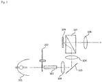
- FIG. 1 is a schematic diagram showing components relating to an optical system of a projector according to an exemplary embodiment of the present invention.
- the projector includes light source 101, color wheel 102, uniforming element 103, lenses 104, 106, mirror 105, TIR (Total Internal Reflection) prism 107, digital micromirror device (DMD) 108 and projection lens 109.
- light source 101 color wheel 102
- uniforming element 103 uniforming element 103
- lenses 104, 106 mirror 105
- TIR (Total Internal Reflection) prism 107 TIR (Total Internal Reflection) prism 107
- DMD digital micromirror device
- Light source 101 is a white light source such as, for example a white color discharge lamp or the like. Light source 101 is configured to emit converging light.
- Uniforming element 103 is formed of a light element such as a light tunnel, rod integrator or the like, having an incident surface at one end face and an outgoing surface at the other end face.
- White light (converging light) from light source 101 enters the incident surface of uniforming element 103.
- a fly-eye lens may be used instead of a light tunnel or the like.
- Color wheel 102 is arranged near the incident end of uniforming element 103.
- Color wheel 102 includes a wheel, in which a filter R having characteristics of transmitting a wavelength range of red (R) light, a filter G having characteristics of transmitting a wavelength range of green (G) light and a filter B having characteristics of transmitting a wavelength range of blue (B) light are arranged in a predetermined order in the circumferential direction, and the center of the wheel is supported by a rotational shaft of a motor. Rotation of the wheel enables emission of red light, green light and blue light in a time-divisional manner.
- the number of filters R, G and B and the dimension of each filter in the circumferential direction can be set as appropriate.
- lens 104 Arranged on the outgoing end side of uniforming element 103 are lens 104, mirror 105 and lens 106 in this order as a means of deflecting the optical path.
- TIR prism 107 is arranged on the deflected optical path.
- TIR prism107 is a total reflection prism assembly that is formed of first and second right angle prisms and has a total reflection surface therein.
- the first and second right angle prisms each have first and second faces that form the legs of the right triangle and a third face that form the hypotenuse, and are arranged so that their third faces are opposite to each other.
- the first face of the first right angle prism forms the incident surface of TIR prism 107 while DMD 108 is arranged so as to be opposite to the second face of the first right angle prism.
- the second face of the second right angle prism forms the outgoing surface of TIR prism 107 while projection lens 109 is arranged on the outgoing surface side.
- TIR prism 107 Light emitted from the outgoing end of uniforming element 103 sequentially passes through lens 104, mirror 105 and lens 106 to enter the incident surface of TIR prism 107. Light incident on TIR prism 107 is totally reflected by the interior total reflection surface and is then emitted from the second face of the first right angle prism. The light emitted from the second face is made to irradiate DMD 108.
- Uniforming element 103 is used to make uniform the illumination distribution on the cross section of the flux of light irradiated on DMD 108.
- illumination information that is in the shape of a square and in which the illumination distribution is uniform is formed near the exit end of uniforming element 103.
- This square illumination information is image-formed on DMD 108 by way of lens 104, mirror 105, lens 106 and TIR prism 107.
- DMD 108 which is a display panel, includes a plurality of micromirrors.
- Each micromirror is configured so as to change its angle in accordance with driving voltage, thus making the angle of reflection different between a state in which the driving voltage in the ON-state is applied and a state in which the driving voltage in the OFF-state is applied.
- Each micromirror is on/off controlled in accordance with image signals whereby the flux of incident light is spatially modulated to form images.
- the image formed by DMD 108 passes through TIR prism 107 and is enlarged and projected on an unillustrated screen by projection lens 109.
- FIG. 2 is a block diagram showing a schematic configuration of components relating to display operation.
- the projector includes panel driver 2 for driving DMD 108, light source driver 3 for driving light source 101, wheel driver 4 for driving color wheel 102, and display control unit 1 that operates these panel driver 2, light source driver 3 and wheel driver 4 to perform display control.
- Display control unit 1 receives video signal S1 from an external device.
- Display control unit 1 operates panel driver 2 so that images in accordance with input video signal S1 are formed by DMD 108 and operates light source driver 3 and wheel driver 4 in synchronization with the image forming operation.
- the external device is, for example, a personal computer or a video device such as recorder.
- the synchronizing signals for synchronizing the image forming operation of DMD 108 with the operations of light source driver 3 and wheel driver 4 may be contained in video signal S1, or may be supplied from an external device, separately from video signal S1.
- Display control unit 1 controls the image forming operation of DMD 108 by a technique called pixel shifting method.
- display control unit 1 uses a combined pixel which is composed of a plurality of pixels as the pixel unit (the pixel unit for projected images) to sequentially form multiple images, and thereby forms frame images.
- display control unit 1 forms one image at the position that is shifted by the distance corresponding to the pixel pitch of DMD 108 in a predetermined direction relative to the other image.
- display control unit 1 handles the pixels of the image formed by individual micromirrors of DMD 108 as subpixels, makes DMD 108 form multiple images, in which a pixel (the aforementioned combined pixel) is composed of a plurality of subpixels, in a time-divisional manner to form frame images, and performs control such that the image forming area of one image is shifted from that of another by one subpixel unit (the pixel pitch of DMD 108) in the predetermined direction.
- a pixel the aforementioned combined pixel
- Display control unit 1 generates image signals S2 and S3 representing images to be formed in a time-divisional manner, from video signal S1.
- Image signals S2 and S3 each have 1/n of the resolution of video signal S1.
- n is the number of subpixels that form one pixel of the image to be formed in a time-divisional manner.
- DMD 108 is a 4K-compatible panel having a resolution of 3,840 (horizontal) x 2,160 (vertical) while one pixel of the image to be formed in a time-divisional manner is composed of 2x2 subpixels
- a signal that represents an image having a resolution of 3,840 (horizontal) x 2,160 (vertical) is supplied as video signal S1
- image signals S2 and S3 each become a signal that represents an image having a resolution of 1,920 (horizontal) x 1,080 (vertical).
- the signal (data) for a pixel is commonly assigned to the 2x2 subpixels that form the pixel.
- Display control unit 1 divides one frame of video signal S1 into the first and second subframes, supplies image signal S2 to panel driver 2 during the first subframe period, and supplies image signal S3 to panel driver 2 during the second subframe period.
- display control unit 1 divides an image field, which is the time unit for displaying the image of one frame of video signal S1, into the first and second subfields and generates image signals S2 and S3 in accordance with the first and second subfields, respectively and supplies them to panel driver 2.
- panel driver 2 makes DMD 108 form an image based on image signal S2.
- panel driver 2 makes DMD 108 form an image based on image signal S3.
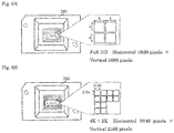
- each of 2x2 pixels a to d of DMD 108 is regarded as subpixel 400 as shown in FIG. 3A and one pixel 401 of the image to be formed in a time-divisional manner is composed of four subpixels 400 as shown Fig. 3B .
- the image based on image signal S2 and the image based on image signal S3 are formed such that the image forming area of each image is shifted by one subpixel unit in a predetermined direction from the other.
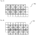
- FIG. 4A shows image forming area 701 that forms part of image A based on image signal S2 whereas FIG. 4B shows image forming area 702 that forms part of image B based on image signal S3.
- image forming area 702 is shifted by one subpixel unit in both the vertical direction (column direction) and horizontal direction (row direction) relative to image forming area 701. That is, image forming area 702 is shifted to the lower right relative to image forming area 701.
- the lower right means the direction of the diagonal line of pixel 401 shown in FIGS. 3B (the direction in which subpixels a and b are arranged).
- each pixel of images A and B is composed of 2x2 subpixels, and the image forming areas of images A and B are shifted by one subpixel unit in the vertical and horizontal directions from each other, as shown in FIGS. 4A and 4B .
- the corresponding pixels of images A and B form respective images that are shifted from each other by 0.5 pixel (1 subpixel) unit in the vertical and horizontal directions.
- the superimposed image of image A and image B will be observed as an image having a pixel count equivalent to the number of subpixels of DMD 108, hence it is practically possible to provide an image having a pixel count equivalent to the pixel count of DMD 108, i.e., 3,840 (horizontal) x 2,160 (vertical).
- display control unit 1 may generate image signals S2 and S3 so that the content (e.g., luminance value) is different between image A and image B.
- display control unit 1 performs a process, in which the average of data (e.g., luminance value) of four subpixels 400 shown in FIG. 3A is calculated and the average value is set to the data for pixel 401 shown in FIG. 3B , for all the subpixels of the image based on video signal S1 to generate image signal S2. Further, display control unit 1 weights each pixel 401 of the image based on image signal S2 to generate image signal S3.
- data e.g., luminance value
- Image signals S2 and S3 should not be limited to the above technique.
- Image signals S2 and S3 may be generated by any other method as long as data of corresponding pixels can be made different from each other.
- image signals S2 and S3 may be generated from video signal S1 by thinning out pixels.
- the combination of four subpixels for average calculation may be different between image signal S2 and image signal S3.
- video signal R that represents red images, video signal G that represents green images and video signal B that represents blue images are supplied to display control unit 1 in a time-divisional manner as video signal S 1.
- Display control unit 1 performs the image forming process according to the above-described pixel shifting control for each of video signals R, G and B.
- the image based on video signal S1 is not formed by DMD 108 without change, but multiple images each having the resolution that is 1/n (n is the number of subpixels forming a whole pixel of the image to be formed by time division) as larger as the resolution of video signal S1 are formed by DMD 108 in a time-divisional manner according to the above-described pixel shifting control.
- one pixel of the image that is formed in a time-divisional manner is composed of 2x2 subpixels as shown in FIGS. 3A and 3B
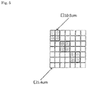
- one subpixel has a size of 5.4 ⁇ m but one pixel (combined pixel) of the image that is formed in a time-divisional manner has a size of 10.8 ⁇ m as shown in FIG. 5 .
- the size of the pixel is two times as large as that of the subpixel in both horizontal and vertical directions.
- the spatial frequency of DMD 108 is N (lp/mm)
- the spatial frequency of the image that is formed in a time-divisional manner is 0.5N (lp/mm).
- the resolving power required for the image to be formed by time division is reduced to half compared to the resolving power required for DMD 108. Accordingly, even if the MTF value of projection lens 109 is less than 50% of the spatial frequency of DMD 108, the resolving power of the projection lens will not be insufficient compared to the formed image as long as the MTF value is equal to or greater than 50% of the spatial frequency that is determined based on the size of the pixel of the image that is formed in a time-divisional manner.
- the frame image is formed by using a plurality of images that are formed in a time-divisional manner, and the pixel of each image (the combined pixel used to form the image) is configured such that the frame image will be formed in subpixel units.
- the forming areas of the pixels (combined pixels used to form the images) corresponding to each other between the images, that are temporally and continuously formed, are shifted by one pixel unit in the predetermined direction. Therefore, when the projected images are observed, it is possible to provide a high-definition image having a pixel count equivalent to that of DMD 108 as the image being watched (the frame image or the superimposed image of the successive images).
- the projector of the present exemplary embodiment when a high-definition display panel is used as DMD 108, since a projection lens having an MTF value of less than 50% of the spatial frequency of the panel can be used, it is possible to prevent an increase in the size and cost of the projection lens.
- Full-HD supporting DMD 201 has an image forming area with a pixel count of 1,920(horizontal) x 1,080(vertical).
- the diagonal dimension of the image forming area is L inches and one pixel size is V(vertical) x h(horizontal).
- 4K-compatible DMD 202 has an image forming area with a pixel count of 3,840(horizontal) x 2,160(vertical).
- the diagonal dimension of the image forming area is L inches, which is the same as that of full HD supporting DMD 201.
- One pixel size is 0.5V(vertical) x 0.5h(horizontal), quarter of the pixel size of the full HD supporting DMD 201.
- the spatial frequency of DMD increases.
- the spatial frequency of full HD supporting DMD 201 is 46.3 lp/mm (line pair per millimeter), whereas the spatial frequency of 4K-compatible DMD 202 is 92.6 lp/mm.
- the spatial frequency of 4K-compatible DMD 202 is twice the spatial frequency of full HD supporting DMD 201, if the projection lens used for full HD supporting DMD 201 is used without change, the resolving power of the projection lens will be insufficient for the image formed by 4K-compatible DMD 202, causing degradation of the image.
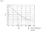
- FIG. 7 shows the MTF characteristics of the projection lens used for full HD supporting DMD 201.
- the horizontal axis represents spatial frequency; and the vertical axis represents the MTF value.
- the MTF value indicates how faithfully the contrast of the projected image can be reproduced by frequency characteristics.
- the values of spatial frequency at points (a) and (b) on the horizontal axis are 46.3 lp/mm and 92.6 lp/mm, respectively. Since the MTF value for the spatial frequency of 46.3 lp/mm is greater than 50%, the resolving power is not insufficient. However, since the MTF value for the spatial frequency of 92.6 lp/mm is significantly lower than 50%, the resolving power is insufficient.
- display control unit 1 handles individual pixels of 4K-compatible DMD 202 as subpixels, and generates image signals S2 and S3 from video signal S1 having a resolution of 3,840 (horizontal) x 2,160 (vertical).
- image A of image signal S2 and image B of image signal S3 are an image in which one pixel is composed of 2x2 subpixels, or an image having a pixel count of 1,920 (horizontal) x 1,080 (vertical).
- Display control unit 1 causes 4K-compatible DMD 202 to form image A and image B in time-divisional manner while shifting the image forming area of image B relative to the image forming area of image A by one subpixel unit in both the vertical and horizontal directions.
- the observed image the superimposed image of images A and B
- the projected surface results in an image having a pixel count of 3,840 (horizontal) x 2,160 (vertical).
- the projection lens is designed to satisfy the condition in which the pixel deviation is equal to or less than 5.4 ⁇ m that corresponds to 0.5 pixel unit.
- this projection lens is used for the 4K-compatible display panel, only 2.7 ⁇ m is permitted as the chromatic aberration of magnification corresponding to the amount of deviation of 0.5 pixel for the pixel size " ⁇ 5.4 ⁇ m” (this means 5.4 ⁇ m x 5.4 ⁇ m). This correction of chromatic aberration of magnification leads to the problem of increase in size and cost of the projection lens.
- the pixel size of the image formed by a DMD can be made to be twice the value of the pixel size of the DMD ( ⁇ 10.8 ⁇ m) by using the pixel-shifting control, it is possible to prevent an increase in the size and cost of the above projection lens.
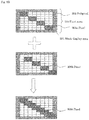
- DMD 108 has a pixel area which is composed of a plurality of pixels and part of the pixel area may be a black display area for displaying black (e.g., the area corresponding to the frame).
- display control unit 1 may be adapted to form multiple images in the pixel area other than black display area in time-divisional manner.
- DMD 108 has pixel area 300 which is composed of multiple subpixels 302, and the outer peripheral part of pixel area 300 is black display area 301.
- display control unit 1 forms the first image in the area other than black display area 301 of pixel area 300.
- an image in which four pixels 303a are laid from the top left to the bottom right is formed as the first image.
- display control unit 1 forms the second image in the area other than black display area 301 of pixel area 300.
- an image in which three pixels 303b laid from the top left to the bottom right is formed as the second image.
- These three pixels 303b correspond to the three pixels 303b from the top left in the first image, and each pixel 303b is formed at the position shifted rightward and downward by one subpixel unit relative to the corresponding pixel 303a.
- the pixel in question is deleted (not displayed).
- the superimposed image of the above first image and second image is formed to accommodate the interior of the area other than black display area 301 of pixel area 300.
- This superimposed image corresponds to the image which is made up of 22 pixels 300c.
- display control unit 1 may be adapted to form multiple images using area other than black display area of the pixel area in a time-divisional manner.
- display control unit 1 forms the first image in pixel area 300.
- an image in which four pixels 303a are laid from the top left to the bottom right is formed as the first image.
- display control unit 1 forms the second image in the area including black display area 301 of pixel area 300.
- an image in which four pixels 303b are laid from the top left to the bottom right is formed as the second image.
- the bottom right pixel 303b is located in black displaying area 301.
- Four pixels 303b correspond to the four pixels 303a in the first image, respectively, and each pixel 303b is formed at the position shifted rightward and downward by one subpixel unit relative to the corresponding pixel 303a.
- the superimposed image of the above first image and second image is formed so as to accommodate the interior of pixel area 300.
- This superimposed image corresponds to the image made up of 25 pixels 300c.
- the image to be formed in a time-divisional manner may and should be an image in which one pixel is composed of a plurality of subpixels that are arranged in n(row) x m(column).
- the pixel may take various forms such as 1x2, 2x1, 2x2, 3x3, and so on.
- the image forming areas of the first and second images are shifted from each other by one subpixel in the row direction.
- the observed image results in an image in which the number of pixels is doubled in the row direction.
- the image forming areas of the first and second images are shifted from each other by one subpixel in the column direction.
- the observed image results in an image in which the number of pixels is doubled in the column direction.
- the first to third image signals that represent the first to third images are generated. Further, one frame is divided into the first to third subframes (or subfields). Then, during the period of the first subframe, the first image based on the first image signal is formed, during the period of the second subframe, the second image based on the second image signal is formed, and during the period of the third subframe, the third image based on the third image signal is formed. In this case, the image forming areas of the first and second images are shifted from each other by one subpixel unit in the row and column directions.
- the image forming areas of the second and third images are shifted from each other by one subpixel unit in the row and column directions. This makes it possible to increase the pixel count of the observed image compared to the configuration where one pixel is formed of four subpixels that are arranged in two rows and two columns, hence provide a high-definition image.
- the pixel size of the images to be formed in a time-divisional manner becomes greater, the condition on the MTF value of the projection lens can be further alleviated.
- the present exemplary embodiment has been described by referring to a single plate type projector equipped with a DMD as a display panel, the present invention should not be limited to this.
- the present invention can be applied to, for example a three-plate type projector, other than single plate type projectors.
- liquid crystal panels and the like may be used as the display panel.
- liquid crystal panel high-temperature polysilicon TFT (Thin Film Transistor) panels and reflection type liquid crystal panels (e.g., liquid crystal on silicon (LCoS)) can be used. Since the single plate type or three-plate type projectors equipped with liquid crystal panels have been well known, description of the configurations is omitted.
- the present exemplary embodiment was described by giving examples using a full-HD supporting panel having a pixel size of " ⁇ 10.8 ⁇ m" and a 4K-compatible panel having a pixel size of " ⁇ 5.4 ⁇ m".
- the application examples of the present invention are not limited to this.
- the present invention can be applied to panels of various resolutions such as WXGA, etc.
- projection lens 109 use is made of a lens having an MTF value that is less than 50% of the spatial frequency of DMD 108 and that is equal to or greater than 50% of the spatial frequency that is determined by the size of the pixel of the image formed in a time-divisional manner.
- MTF value is the threshold based on the condition generally imposed on the MTF value.
- the threshold may and should be set so as not to cause any insufficient resolution, preferably set at "50%” or more preferably "60%”.
- display control unit 1 generates, from input video signal S1, multiple image signals that represent multiple images to be formed in a time-divisional manner, respectively.
- display control unit 1 may be supplied from an external device to display control unit 1.
- the present invention can take the modes described in the following SUPPLEMENTARY NOTES 1 to 14, but should not be limited to these modes.
- control means corresponds to display control unit 1 and the image forming means corresponds to DMD 108, panel driver 2 and the like.
- the projecting means includes projection lens 109.
- the frame image is formed in pixel units, it is possible to provide projection images having a pixel count equivalent to that of the pixel area.
Landscapes
- Engineering & Computer Science (AREA)
- Multimedia (AREA)
- Signal Processing (AREA)
- Physics & Mathematics (AREA)
- Computer Hardware Design (AREA)
- General Physics & Mathematics (AREA)
- Theoretical Computer Science (AREA)
- Projection Apparatus (AREA)
- Transforming Electric Information Into Light Information (AREA)
Applications Claiming Priority (1)
| Application Number | Priority Date | Filing Date | Title |
|---|---|---|---|
| PCT/JP2014/052863 WO2015118651A1 (fr) | 2014-02-07 | 2014-02-07 | Projecteur et procédé d'affichage d'image |
Publications (2)
| Publication Number | Publication Date |
|---|---|
| EP3104221A1 true EP3104221A1 (fr) | 2016-12-14 |
| EP3104221A4 EP3104221A4 (fr) | 2017-10-11 |
Family
ID=53777483
Family Applications (1)
| Application Number | Title | Priority Date | Filing Date |
|---|---|---|---|
| EP14882106.9A Withdrawn EP3104221A4 (fr) | 2014-02-07 | 2014-02-07 | Projecteur et procédé d'affichage d'image |
Country Status (5)
| Country | Link |
|---|---|
| US (1) | US9838655B2 (fr) |
| EP (1) | EP3104221A4 (fr) |
| JP (1) | JP6172773B2 (fr) |
| CN (1) | CN105980926B (fr) |
| WO (1) | WO2015118651A1 (fr) |
Cited By (1)
| Publication number | Priority date | Publication date | Assignee | Title |
|---|---|---|---|---|
| US11862079B2 (en) * | 2021-12-07 | 2024-01-02 | Lg Display Co., Ltd. | Display device |
Families Citing this family (9)
| Publication number | Priority date | Publication date | Assignee | Title |
|---|---|---|---|---|
| US10206040B2 (en) * | 2015-10-30 | 2019-02-12 | Essential Products, Inc. | Microphone array for generating virtual sound field |
| JP6407330B2 (ja) * | 2017-03-10 | 2018-10-17 | キヤノン株式会社 | 画像投射装置 |
| WO2019041622A1 (fr) * | 2017-08-30 | 2019-03-07 | 深圳光峰科技股份有限公司 | Système de projection |
| CN109491187B (zh) | 2017-09-13 | 2021-05-04 | 深圳光峰科技股份有限公司 | 波长转换装置、光源系统及投影设备 |
| JP2019066806A (ja) * | 2017-10-05 | 2019-04-25 | キヤノン株式会社 | 投影装置およびその制御方法、プログラム並びに記憶媒体 |
| KR102531925B1 (ko) | 2017-11-08 | 2023-05-16 | 엘지전자 주식회사 | 프로젝터 및 그의 동작 방법 |
| CN110221505A (zh) * | 2018-03-02 | 2019-09-10 | 台达电子工业股份有限公司 | 投影装置及投影方法 |
| US11079668B1 (en) | 2020-07-07 | 2021-08-03 | Mirraviz, Inc. | Reflective display |
| US11722648B2 (en) | 2020-07-07 | 2023-08-08 | Mirraviz, Inc. | Reflective display |
Family Cites Families (14)
| Publication number | Priority date | Publication date | Assignee | Title |
|---|---|---|---|---|
| JP2939826B2 (ja) * | 1990-09-03 | 1999-08-25 | 日本電信電話株式会社 | 投影表示装置 |
| JPH10222133A (ja) * | 1997-02-10 | 1998-08-21 | Sony Corp | 液晶表示装置の駆動回路 |
| JP4846940B2 (ja) * | 2000-08-30 | 2011-12-28 | 株式会社リコー | 画像表示装置 |
| US7125121B2 (en) * | 2002-02-25 | 2006-10-24 | Ricoh Company, Ltd. | Image display apparatus |
| US7172288B2 (en) * | 2003-07-31 | 2007-02-06 | Hewlett-Packard Development Company, L.P. | Display device including a spatial light modulator with plural image regions |
| JP4103740B2 (ja) * | 2003-09-10 | 2008-06-18 | セイコーエプソン株式会社 | 画像表示装置、画像表示方法及び画像表示プログラム |
| US7358930B2 (en) * | 2003-10-14 | 2008-04-15 | Hewlett-Packard Development Company, L.P. | Display system with scrolling color and wobble device |
| US20050093894A1 (en) | 2003-10-30 | 2005-05-05 | Tretter Daniel R. | Generating an displaying spatially offset sub-frames on different types of grids |
| US7182463B2 (en) * | 2003-12-23 | 2007-02-27 | 3M Innovative Properties Company | Pixel-shifting projection lens assembly to provide optical interlacing for increased addressability |
| JP2006047414A (ja) | 2004-07-30 | 2006-02-16 | Olympus Corp | カラー表示装置 |
| JP2008076746A (ja) * | 2006-09-21 | 2008-04-03 | Seiko Epson Corp | プロジェクタ |
| JP5159407B2 (ja) | 2008-04-16 | 2013-03-06 | キヤノン株式会社 | アクティブマトリクス基板、反射型液晶表示装置、及び液晶プロジェクターシステム |
| JP2010243545A (ja) * | 2009-04-01 | 2010-10-28 | Seiko Epson Corp | プロジェクターの光変調素子位置調整方法およびプロジェクター |
| JP6390944B2 (ja) | 2013-05-20 | 2018-09-19 | パナソニックIpマネジメント株式会社 | 投写型映像表示装置 |
-
2014
- 2014-02-07 JP JP2015561109A patent/JP6172773B2/ja active Active
- 2014-02-07 EP EP14882106.9A patent/EP3104221A4/fr not_active Withdrawn
- 2014-02-07 US US15/104,519 patent/US9838655B2/en active Active
- 2014-02-07 WO PCT/JP2014/052863 patent/WO2015118651A1/fr not_active Ceased
- 2014-02-07 CN CN201480074979.5A patent/CN105980926B/zh not_active Expired - Fee Related
Cited By (1)
| Publication number | Priority date | Publication date | Assignee | Title |
|---|---|---|---|---|
| US11862079B2 (en) * | 2021-12-07 | 2024-01-02 | Lg Display Co., Ltd. | Display device |
Also Published As
| Publication number | Publication date |
|---|---|
| EP3104221A4 (fr) | 2017-10-11 |
| JPWO2015118651A1 (ja) | 2017-03-23 |
| WO2015118651A1 (fr) | 2015-08-13 |
| CN105980926B (zh) | 2017-09-08 |
| JP6172773B2 (ja) | 2017-08-02 |
| CN105980926A (zh) | 2016-09-28 |
| US9838655B2 (en) | 2017-12-05 |
| US20160316182A1 (en) | 2016-10-27 |
Similar Documents
| Publication | Publication Date | Title |
|---|---|---|
| US9838655B2 (en) | Projector and image displaying method | |
| US11057596B2 (en) | Image projection apparatus and its control method | |
| JP4796052B2 (ja) | 3次元で画像を表示する方法およびシステム | |
| JP2009139968A (ja) | スクローリングカラーおよびウォブルデバイスを備えた表示システム | |
| CN100423047C (zh) | 光调制装置和光学显示装置以及它们的控制方法 | |
| CN115243103B (zh) | 图像拆分方法与图像显示方法 | |
| US20070211218A1 (en) | Image display device and projector | |
| US10991286B2 (en) | Electro-optical device including a light path shifting element and method for controlling the same | |
| US7086736B2 (en) | Display system with sequential color and wobble device | |
| JP2007535705A (ja) | 全ての画像サブフレームロケーションよりも少ない画像サブフレームロケーションへの最下位カラー画像ビットプレーンの表示方法 | |
| US9607563B2 (en) | Liquid crystal display device, method for driving liquid crystal display device, and electronic apparatus | |
| US20060023003A1 (en) | Color display apparatus | |
| JP2006162639A (ja) | 液晶表示装置およびプロジェクタ | |
| KR20050039593A (ko) | 디스플레이 시스템 및 방법 | |
| JP2019041189A (ja) | 画像投射装置およびその制御方法 | |
| JP6969198B2 (ja) | 液晶パネル、プロジェクターおよび電子機器 | |
| JP2008090239A (ja) | 投射型画像表示装置 | |
| JP4957090B2 (ja) | 表示装置及び映像表示装置 | |
| JP6255836B2 (ja) | 駆動装置、駆動方法、表示装置および電子機器 | |
| JP2007225890A (ja) | 投写型表示装置 | |
| JP2005156723A (ja) | 表示装置 | |
| JP2008076746A (ja) | プロジェクタ | |
| JP2006523854A (ja) | マトリックス形アドレス指定方式ディスプレイで起こるピクセル欠陥及びサブピクセル欠陥をシミュレーションするための方法と回路構成 |
Legal Events
| Date | Code | Title | Description |
|---|---|---|---|
| PUAI | Public reference made under article 153(3) epc to a published international application that has entered the european phase |
Free format text: ORIGINAL CODE: 0009012 |
|
| 17P | Request for examination filed |
Effective date: 20160907 |
|
| AK | Designated contracting states |
Kind code of ref document: A1 Designated state(s): AL AT BE BG CH CY CZ DE DK EE ES FI FR GB GR HR HU IE IS IT LI LT LU LV MC MK MT NL NO PL PT RO RS SE SI SK SM TR |
|
| AX | Request for extension of the european patent |
Extension state: BA ME |
|
| DAX | Request for extension of the european patent (deleted) | ||
| A4 | Supplementary search report drawn up and despatched |
Effective date: 20170908 |
|
| RIC1 | Information provided on ipc code assigned before grant |
Ipc: G09G 3/20 20060101ALI20170904BHEP Ipc: G03B 21/00 20060101AFI20170904BHEP Ipc: G09G 3/00 20060101ALI20170904BHEP Ipc: H04N 5/74 20060101ALI20170904BHEP |
|
| 17Q | First examination report despatched |
Effective date: 20200616 |
|
| STAA | Information on the status of an ep patent application or granted ep patent |
Free format text: STATUS: THE APPLICATION HAS BEEN WITHDRAWN |
|
| 18W | Application withdrawn |
Effective date: 20200723 |