EP3104302B1 - Verfahren zur digitalisierung technischer dokumente - Google Patents
Verfahren zur digitalisierung technischer dokumente Download PDFInfo
- Publication number
- EP3104302B1 EP3104302B1 EP15171210.6A EP15171210A EP3104302B1 EP 3104302 B1 EP3104302 B1 EP 3104302B1 EP 15171210 A EP15171210 A EP 15171210A EP 3104302 B1 EP3104302 B1 EP 3104302B1
- Authority
- EP
- European Patent Office
- Prior art keywords
- parametric
- symbols
- symbol
- search window
- identified
- Prior art date
- Legal status (The legal status is an assumption and is not a legal conclusion. Google has not performed a legal analysis and makes no representation as to the accuracy of the status listed.)
- Active
Links
Images


Classifications
-
- G—PHYSICS
- G06—COMPUTING OR CALCULATING; COUNTING
- G06V—IMAGE OR VIDEO RECOGNITION OR UNDERSTANDING
- G06V30/00—Character recognition; Recognising digital ink; Document-oriented image-based pattern recognition
- G06V30/10—Character recognition
- G06V30/32—Digital ink
- G06V30/36—Matching; Classification
- G06V30/373—Matching; Classification using a special pattern or subpattern alphabet
-
- G—PHYSICS
- G06—COMPUTING OR CALCULATING; COUNTING
- G06V—IMAGE OR VIDEO RECOGNITION OR UNDERSTANDING
- G06V30/00—Character recognition; Recognising digital ink; Document-oriented image-based pattern recognition
- G06V30/40—Document-oriented image-based pattern recognition
- G06V30/42—Document-oriented image-based pattern recognition based on the type of document
- G06V30/422—Technical drawings; Geographical maps
Definitions
- the present disclosure relates to the field of information management in engineering and modernisation projects.
- OCR Optical Character Recognition
- CHIEW-LAN TAI ET AL "An object-oriented progressive-simplification-based vectorization system for engineering drawings: model, algorithm , and performance', IEEE TRANSACTIONS ON PATTERN ANALYSIS AND MACHINE INTELLIGENCE.
- IEEE COMPUTER SOCIETY, USA, vol. 24, no. 8, 1 August 2002 (2002-08-01), pages 1048-1060, ISSN: 0162-8828, DOI: 10.1109/ ITPAMI.2002.1023802 discloses a method of imitating the way humans read engineering drawings by means of a one- phase object-oriented vectorization model that recognizes each class of graphic objects from their natural characteristics. Each ground truth graphic object is recognized directly in its entirety at the pixel level.
- the raster image is progressively simplified by erasing recognized graphic objects to eliminate their interference with subsequent recognition.
- EP 1 876553 A1 discloses a method for generating process graphics for an industrial process, comprising the following steps: recording a digital image of a graphic in the form of a sketch drawn free-hand by a user, said sketch representing an engineering process element into a computing device, processing the digital image to provide an enhanced process graphic element, and identifying the sketch as at least one process graphic element by using at least a library providing information helping to interpret said sketch and geometrical sketch elements.
- US 2010/250622 A1 discloses a method ofautomatic generation of a system specification description (SSD) file from a diagram of an electrical installation, the diagram comprising conventional symbols representing the electrical elements of the said installation and attributes representing the specific electrical characteristics of each electrical element.
- This method includes the following steps: identifying the conventional symbols from an image of the said electrical diagram, associating the identified type signals with known entities, identif4ng, from the image, the functional blocks, the graphic instances that represent each conventional symbol, the attributes associated with each conventional symbol, and the topology of the electrical connections of each conventional symbol, associating a standard label with each identified conventional symbol, generating a correspondence table containing each identified symbol and the corresponding standard label; and storing in an SSD type file the said correspondence table and the electrical topology of the identified conventional symbols.
- SSD system specification description
- an object of the present disclosure is to solve, or at least mitigate, the problems of the prior art.
- a method of digitalising engineering documents describing a plant topology comprising obtaining a digital image of the engineering documents, which digital image comprises: a plurality of objects, each object being one of a plurality of types of non-parametric symbols which are characterised by multi-curve forms, each type of non-parametric symbol representing a unique plant asset class, or one of a plurality of types of first parametric symbols which are characterised by a single-curve form, each type of first parametric symbol representing a unique plant asset class, second type of parametric symbols representing connections between the objects, and text annotations classifying and identifying each object; identifying the non-parametric symbols by comparing them with reference non-parametric symbols, and based on the identifying assigning to each identified non-parametric symbol a plant asset class, determining the coordinates of the non-parametric symbols in the digital image, identifying the first parametric symbols, and based on the identifying assigning to each identified first parametric symbol
- the method is applicable for the digitalization of graphic engineering documents, specifically Piping & Instrumentation Diagrams (P&IDs).
- P&IDs Piping & Instrumentation Diagrams
- the use of the method proposed herein can potentially increase the efficiency of reengineering steps and is particularly relevant in brownfield projects within a broad range of industries such as chemical, pharmaceutical, oil & gas, pulp & paper, total power systems, and process automation.
- the present method addresses the conversion of a wider range of connectivity diagrams and graphical process descriptions which are key-documents for reengineering projects in process industry. It combines geometric and semantic techniques to identify the connectivity between graphical symbols and assign specific connectivity types. The method further focusses on the derivation of high-level digital models which can be automatically used for reengineering and operational tasks. Furthermore, the use of this invention does not require high expertise. The digitalization of engineering documents can be performed by the user without the need for hiring external companies for the task, thereby resulting in significant savings.
- the steps of assigning involve utilising an OCR algorithm to identify the text annotations.
- the steps of identifying the non-parametric symbols and the first parametric symbols involves utilising an OSR algorithm, and the detecting of the second parametric symbols involves utilising an OSR algorithm.
- the step of identifying the non-parametric symbols further includes removing the non-parametric symbols from the digital image when they have been identified.
- the step of identifying the first parametric symbols further includes removing the first parametric symbols from the digital image when they have been identified.
- the step of determining the connections involves removing each second parametric symbol from the digital image when a corresponding connection has been determined.
- the step of identifying the non-parametric symbols involves rotating a non-parametric symbol relative to a reference non-parametric symbol.
- the rotating is in the range of 0-360 degrees.
- the step of identifying the non-parametric symbols involves scaling a non-parametric symbol relative to a reference non-parametric symbol.
- the scaling is in the range of 50-200 %.
- a cover limit is utilised so that matches can be found also when a non-parametric symbol is covered below the cover limit.
- One embodiment comprises assigning unique identifiers to the second parametric symbols.
- One embodiment comprises generating an intermediate model of the plant topology prior to the step of generating the model of the plant topology, wherein the intermediate model of the plant topology includes a connectivity matrix describing connections between the objects by means of the classified second type of parametric symbols, and a coordinates table with the coordinates of the objects, and wherein the model of the plant topology is generated based on the intermediate model.
- the model of the plant topology is an object oriented model.
- a computer program for digitalising engineering documents describing a plant topology comprising computer code which, when run on a processing unit of digitalisation device, causes the digitalisation device to obtain a digital image of the engineering documents, which digital image comprises a plurality of objects, each object being one of a plurality of types of non-parametric symbols which are characterised by multi-curve forms, each type of non-parametric symbol representing a unique plant asset class, or one of a plurality of types of first parametric symbols which are characterised by a single-curve form, each type of first parametric symbol representing a unique plant asset class, second type of parametric symbols representing connections between the objects, and text annotations classifying and identifying each object; identify the non-parametric symbols by comparing them with reference non-parametric symbols, and based on the identifying assign to each identified non-parametric symbol a plant asset class, determine the coordinates of the non-parametric symbols in the digital image, identify the first parametric symbols, and
- a computer program product comprising a computer program according the second aspect, and a storage unit on which the computer program is stored.
- the present disclosure describes a method for digitalizing engineering documents based on optical recognition and semantic analysis.
- the underlying notion of this approach is that certain graphical engineering documents, such as P&IDs, can be converted into object-oriented (OO) models through the systematic recognition of text and symbolic forms, the detection of their connections, and the analysis of their domain-specific connotation.
- OO object-oriented
- a method which captures the plant topology, connectivity, and annotations of design drawings typically stored on paper or elementary digital formats is disclosed.
- Such a workflow and its underlying concepts are capable of drastically speeding-up the digitalization of legacy documents.
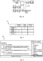
- the method relies on the notion that engineering documents are composed of four fundamental elements. These elements are 1) parametric symbols that are symbols that can be characterised by single curve forms such as circles, rectangles, lines and curves, 2) non-parametric symbols that are symbols that can be characterised by multi-curve forms, 3) text annotations, and 4) underlying semantic content, as shown in Fig. 1 .
- the parametric symbols are herein divided into first parametric symbols and second parametric symbols.
- the first parametric symbols and the non-parametric symbols define objects that represent plant asset classes, for example plant devices or plant processes.
- the second parametric symbols represent connections between the objects.
- the second parametric symbols may also be seen to represent plant asset classes, e.g. pipes and wires.
- this disclosure proposes three main procedures for the conversion execution.
- Low-level recognition OSR and OCR for the identification of non-parametric and parametric symbols and text annotations.
- High-level recognition Semantic analysis for the enhancement of the recognition procedure and the improvement of expression capabilities for model description.
- P&IDs are embodied as digital images on raster images.
- legacy documents are typically maintained either on paper or elementary digital formats such as PDF or CAD files.
- preprocessing steps should be taken beforehand.
- paper documents are to be scanned and stored as raster files whilst elementary digital documents are to be exported through virtual printing and rasterization, or snapshotting.
- Fig. 2 depicts a block diagram of a digitalisation device 1 configured to digitalise engineering documents describing a plant topology.
- the digitalisation device 1 comprises an input unit 3 configured to receive a digital image of an engineering document describing a plant topology, a storage unit 7 comprising computer code, a processing unit 5 and an output unit 9, which output unit 9 is configured to communicate with the processing unit 5 and to output a model of the plant topology created by the processing unit 5 based on a digital image of engineering documents.
- the digitalisation device 1 is configured to digitalise engineering documents according to the methods that will be described in more detail in the following when the computer code stored in the storage unit 7 is run on the processing unit 5.
- Fig. 3a shows a simplified example of a digital image 11 of an engineering document in the form of a P&ID.
- the engineering document describes a plant topology, i.e. the plant devices and their connections, in a schematic manner.
- a vessel E100 connected to a valve V200 by means of a pipe Pi002 and a sensor L101 is connected to the vessel E100.
- the vessel E100 and the valve V200 are examples of non-parametric symbols 13.
- the sensor L101 is an example of a first parametric symbol 15.
- the pipe Pi200 is an example of a second parametric symbol 17.
- the connection 19 between the vessel E100 and the sensor L101 is another example of a second parametric symbol, in this case not a flow coupling as in the case of the pipe Pi002 but an information link.
- the type of connection e.g. flow coupling or information link, is determined by the digitalisation method, thereby contributing to a full identification of the plant topology presented in an engineering document.
- a digital image 11 of an engineering document describing a plant topology is obtained.
- the digital image 11 is obtained either by the input unit 3 and delivered to the processing unit 5 or obtained by the processing unit 5 itself for example in the event of a file conversion operation.
- contours of image contours representing graphic components such as objects, connections, and text annotations are extracted.
- Such a procedure may be executed based on gradient methods as a step prior to optical recognition.
- the non-parametric symbols are identified by comparing them with reference non-parametric symbols. Based on the identifying a plant asset class is assigned to each identified non-parametric symbol. Thus, for example the non-parametric symbol 13 that is the vessel E100 is assigned the plant asset class "vessel". In step S2 OSR may be used to identify the non-parametric symbols 13.
- the non-parametric symbols are preferably compared with pre-defined libraries/databases of reference non-parametric symbols accounting for typical non-parametric symbols found within the analysed digital image 11.
- a predefined library can represent, for instance, plant asset catalogues or sets of symbols commonly used to embody specific plant devices or plant processes.
- the definition of libraries allow not only for modularity, which in turn results in more efficient search procedures, but also for effective capture and reuse of structural knowledge within different projects.
- the matching criterion employed at this stage is based on the geometric features of the examined non-parametric symbols.
- geometric properties may be utilised to guarantee an exhaustive search of possible matches.
- three geometric properties may be utilised, namely rotation, scaling and partial overlapping which are cases when part of a non-parametric symbol is partially overlapped by other another object and/or by a text annotation.
- the step S2 of identifying the non-parametric symbols may involves rotating a non-parametric symbol relative to a reference non-parametric symbol if necessary.
- the rotation may preferably be performed in a range of 0 to 360 degrees.
- the step S2 of identifying the non-parametric symbols may also involve scaling a non-parametric symbol relative to a reference non-parametric symbol if necessary.
- the scaling may for example be performed in the range of 50-200 % of a non-parametric symbol.
- a cover limit or occlusion limit may be utilised so that matches can be found also when a non-parametric symbol is covered below the cover limit i.e. covered not more than what is defined by the cover limit. Accordingly, cover limits can be defined so that matches can be found despite this condition. Typical cover limit values are defined in the range 0-20%.
- Matching scores quantifying the extent of resemblance between found candidates of non-parametric symbols and respective reference non-parametric symbols may be used to define levels of confidence within the identification process.
- a step S3 the coordinates of the non-parametric symbols in the digital image are determined. This procedure may be performed simultaneously with the identification, each time a match is found, i.e. when an object is identified as a non-parametric symbol.
- the coordinates are stored and optionally the curves representing an identified non-parametric symbol are removed or suppressed from the digital image 11 in order to facilitate the recognition of further objects.
- a step S4 the first parametric symbols 15 are identified. Furthermore, based on the identifying a plant asset class is assigned to each identified first parametric symbol. Thus, for example the first parametric symbol 15 that is the sensor L101 is assigned the plant asset class "sensor”. In step S4 OSR may be used to identify the first parametric symbols 15.
- steps S2 and S4 may alternatively be performed in opposite order than presented herein, or in parallel.
- Recognition methods used in step S4 are capable of finding possible candidates regardless of their size and orientation. Thresholds can be set to define the minimum dimensions of first parametric objects and avoid thereby the misinterpretation of characters as first parametric symbols, e.g. characters O.
- a step S5 the coordinates of the first parametric symbols in the digital image are determined.
- step S2 the reliability of the recognition process can be adjusted based on calculated matching scores.
- coordinates of found objects are stored and their respective curves may be removed or suppressed from the digital image 11.
- a respective search window is generated for each identified non-parametric symbol 13.
- one search window W is shown, generated based on the coordinates of the vessel E100.
- Each search window is positioned in the digital image based on the coordinates of the corresponding identified non-parametric symbol.
- each search window is positioned so that it includes the area surrounding the corresponding identified non-parametric symbol.
- the size of a search window is typically proportional to the dimensions of the identified non-parametric form in question or could be conveniently defined by the user depending upon the considered non-parametric symbol.
- a text annotation 18 contained in the corresponding search window is assigned to the identified non-parametric symbol in question.
- an OCR algorithm searches for text annotation within the search window, finding characters which are collected in a string and assigned as text annotation or tag identifier of the respective object.
- the assigned text annotation would be "E100".
- the assigning involves selecting that text annotation contained in the search window which includes a character that corresponds to the plant asset class of the corresponding non-parametric symbol.
- the character may for example be an alphanumeric character and it may have a predefined position in the text string representing the text annotation. For instance, if the analysed search window surrounds an object A, possible text annotations or tag identifiers are to start with a specific alphabetic character X followed by a specific number of alphanumerical characters YYY which results in a tag of type XYYY. All strings not satisfying such a rule are discarded and consequently a unique tag is assigned to the object. An example of this situation is shown in Fig.
- the search window W for the vessel E100 contains two text annotations, namely E100 and Pi003.
- the character "E” determines that the text annotation "E100” should be assigned to the non-parametric symbol describing the vessel, and thus that the text annotation Pi003 should be discarded.
- the method may trigger a warning notifying the user of the problem.
- found text annotations may be removed or suppressed from the digital image to facilitate the identification of remaining objects and text annotations.
- a respective search window is generated for each identified first parametric symbol. Similarly to the process explained hereabove, each search window is positioned based on the coordinates of the corresponding identified first parametric symbol.
- a text annotation contained in the corresponding search window is assigned to the concerned identified first parametric symbol.
- the assigning involves selecting that text annotation contained in the search window which includes a character that corresponds to the plant asset class of the corresponding first parametric symbol.
- the character may for example be an alphanumeric character and it may have a predefined position in the text string representing the text annotation.
- a similar OCR search approach is followed here as for the text annotation assignment for non-parametric symbols, i.e. strings are found, nomenclature rules are applied to ensure naming consistency, and warnings may be triggered to inform about doubtful identifications.
- connections between the objects 13, 15 are determined by detecting the second parametric symbols and by determining their proximity to the objects 13, 15.
- the detecting may include assigning a plant asset class to the second parametric symbols.
- Search windows may also be created based on the coordinates of the second parametric symbols, to thereby assign text annotations to the second parametric symbols, if such text annotations are present.
- lines represent simple connections and are not tagged.
- the approach is to assign fictive and unique text annotations or tag identifiers so that lines can be subsequently referenced to by the allocated text annotation.
- the method may hence include assigning unique identifiers to those second parametric symbols for which no text annotation can be found.
- connections within engineering diagrams are constructed based on polyline arrangements. Hence, the determining of connections requires as a first step to unify contiguous lines so that the second parametric symbols in the form of single links can be identified. At that point, the proximity of such second parametric symbols to objects is verified and the underlying connectivity of the diagram derived.
- the connectivity stage implements semantic analysis to refine the definition of specific connection classes. Regardless of whether the same type of lines is used to represent different connections within the P&ID, the semantics of related objects are analysed so that appropriate interfaces and links are created within the respective derived objects. In case of doubtful connectivity detection, e.g. due to the proximity of several objects, according to one variation a warning is triggered.
- each second parametric symbol is classified.
- the classification of each second parametric symbol is based on the plant asset classes of the objects it connects to or based on the text annotation assigned to the respective object it connects to.
- the plant asset classes i.e. "vessel” and "sensor”
- the text annotations "E100" and "L101” are used for the classification.
- the letters "E” and "L” are reserved for different plant asset classes, in this example to vessel and sensor, respectively. Thereby, the type of connection may be determined.
- a model 23 of the plant topology is generated based on the non-parametric symbols, the first parametric symbols, the text annotations and the second parametric symbols.
- This model may for example be an OO model.
- the intermediate model 21 of the plant topology may include a connectivity matrix describing connections between the objects by means of the classified second type of parametric symbols, and a coordinates table with the coordinates of the objects.
- An example of a connectivity matrix 21 based on the digital image 11 is shown in Fig. 4 .
- the connectivity and position of the found objects can be represented by the connectivity matrix and the coordinates table, respectively.
- the connectivity matrix may have as first row and column the list of recognized objects and some of the second parametric symbols, i.e. those that have a plant asset class assigned to it. These objects and second parametric symbols may be referenced by their plant asset class and text annotation, e.g. vessel E100.
- the inner entries of the matrix represent the connectivity and classification between the elements in the first row and first column.
- the class of connection are indicated by distinctive names within the matrix entries, for example F for material flow and I for information flow.
- vessel E100 has a flow material connection to pipe Pi002 and vice versa.
- Possible representations of the connectivity matrix can for example be embodied on MS Excel spreadsheets or data tables in C# Windows Forms environment.
- the model 23 of the plant topology may be generated based on the intermediate model of the plant topology. Based on the information collected by the intermediate model 23 an OO model may be generated in step S12.
- the procedure starts by creating one item for every entry within the first column of the connectivity matrix.
- interfaces are created by considering the number of connections found for the given item, i.e. non-empty entries within the respective row/column of the connectivity matrix, and corresponding interface classes are defined in accordance with the content of the cells.
Landscapes
- Engineering & Computer Science (AREA)
- Computer Vision & Pattern Recognition (AREA)
- Physics & Mathematics (AREA)
- General Physics & Mathematics (AREA)
- Multimedia (AREA)
- Theoretical Computer Science (AREA)
- Artificial Intelligence (AREA)
- Stored Programmes (AREA)
Claims (15)
- Verfahren zum Digitalisieren technischer Dokumente, die eine Anlagentopologie beschreiben, wobei das Verfahren Folgendes umfasst:Erhalten (S1) eines digitalen Bildes (11) der technischen Dokumente, wobei das digitale Bild (11) Folgendes umfasst:- mehrere Objekte, wobei jedes Objekt eine von mehreren Arten von nicht-parametrischen Symbolen (13), die durch Mehrfachbogenformen ausgezeichnet sind, ist, wobei jede Art von nicht-parametrischen Symbolen (13) eine eindeutige Anlagenklasse repräsentiert, oder eine von mehreren Arten von ersten parametrischen Symbolen (15), die durch eine Einfachbogenform ausgezeichnet sind, ist, wobei jede Art von ersten parametrischen Symbolen (15) eine eindeutige Anlagenklasse repräsentiert,- eine zweite Art von parametrischen Symbolen (17, 17), die Verbindungen zwischen den Objekten (13, 15) repräsentieren, und- Textvermerke (18), die jedes Objekt (13, 15) klassifizieren und identifizieren;Identifizieren (S2) der nicht-parametrischen Symbole (13), indem sie mit nicht-parametrischen Referenzsymbolen verglichen werden, und auf der Grundlage des Identifizierens Zuweisen einer Anlagenklasse zu jedem identifizierten nicht-parametrischen Symbol (13),Bestimmen (S3) der Koordinaten des nicht-parametrischen Symbols (13) in dem digitalen Bild (11),Identifizieren (S4) des ersten parametrischen Symbols (15) und auf der Grundlage des Identifizierens Zuweisen einer Anlagenklasse zu jedem identifizierten ersten parametrischen Symbol (15),Bestimmen (S5) der Koordinaten des ersten parametrischen Symbols (15) in dem digitalen Bild (11),Erzeugen (S6) eines Suchfensters (W) für jedes identifizierte nicht-parametrische Symbol (13), wobei jedes Suchfenster (W) auf der Grundlage der Koordinaten des entsprechenden identifizierten nicht-parametrischen Symbols (13) positioniert wird,Zuweisen (S7) eines Textvermerks (18), der in dem entsprechenden Suchfenster (W) enthalten ist, zu jedem identifizierten nicht-parametrischen Symbol (13), wobei dann, wenn mehr als ein Textvermerk (18) in einem Suchfenster (W) vorliegt, das Zuweisen das Auswählen des Textvermerks (18), der in dem Suchfenster (W) enthalten ist, das ein Zeichen enthält, das der Anlagenklasse des entsprechenden nicht-parametrischen Symbols (13) entspricht, umfasst,Erzeugen (S8) eines Suchfensters (W) für jedes identifizierte parametrische Symbol (15), wobei jedes Suchfenster (W) auf der Grundlage der Koordinaten des entsprechenden identifizierten parametrischen Symbols (15) positioniert wird,Zuweisen (S9) eines Textvermerks (18), der in dem entsprechenden Suchfenster (W) enthalten ist, zu jedem identifizierten parametrischen Symbol (15), wobei dann, wenn mehr als ein Textvermerk (18) in einem Suchfenster (W) vorliegt, das Zuweisen das Auswählen des Textvermerks (18), der in dem Suchfenster (W) enthalten ist, das ein Zeichen enthält, das der Anlagenklasse des entsprechenden parametrischen Symbols (15) entspricht, umfasst,Bestimmen (S10) von Verbindungen zwischen den Objekten (13, 15) durch Detektieren der zweiten parametrischen Symbole (17, 19) und durch Bestimmen ihrer Nähe zu den Objekten (13, 15),Klassifizieren (S11) der zweiten parametrischen Symbole (17, 19), wobei jedes zweite parametrische Symbol (17, 19) auf der Grundlage der Anlagenklassen der Objekte (13, 15), mit denen es verbunden ist, oder auf der Grundlage der Textvermerke (18), die den Objekten (13, 15), mit denen es verbunden ist, zugewiesen ist, klassifiziert wird, undErzeugen (S12) eines Modells (23) der Anlagentopologie auf der Grundlage der nicht-parametrischen Symbole (13), der ersten parametrischen Symbole (15), der zugewiesenen Textvermerke (18) und der klassifizierten zweiten parametrischen Symbole.
- Verfahren nach Anspruch 1, wobei die Schritte des Zuweisens (S7, S9) das Verwenden eines OCR-Algorithmus umfassen, um die Textvermerke (18) zu identifizieren.
- Verfahren nach Anspruch 1 oder 2, wobei die Schritte des Identifizierens der nicht-parametrischen Symbole (13) und der ersten parametrischen Symbole (15) das Verwenden eines optischen Symbolerkennungsalgorithmus, OSR-Algorithmus, umfassen und das Detektieren der zweiten parametrischen Symbole das Verwenden eines OSR-Algorithmus umfasst.
- Verfahren nach einem der vorhergehenden Ansprüche, wobei der Schritt des Identifizierens (S2) der nicht-parametrischen Symbole (13) ferner das Entfernen der nicht-parametrischen Symbole (13) aus dem digitalen Bild (11) enthält, wenn sie identifiziert worden sind.
- Verfahren nach einem der vorhergehenden Ansprüche, wobei der Schritt des Identifizierens (S4) der ersten parametrischen Symbole (15) ferner das Entfernen der ersten parametrischen Symbole (15) aus dem digitalen Bild (11) enthält, wenn sie identifiziert worden sind.
- Verfahren nach einem der vorhergehenden Ansprüche, wobei der Schritt des Bestimmens (S10) der Verbindungen das Entfernen jeweils der zweiten parametrischen Symbole (17, 19) aus dem digitalen Bild umfasst, wenn eine entsprechende Verbindung bestimmt wurde.
- Verfahren nach einem der vorhergehenden Ansprüche, wobei der Schritt des Identifizierens (S2) der nicht-parametrischen Symbole das Drehen eines nicht-parametrischen Symbols (13) in Bezug auf ein nicht-parametrisches Referenzsymbol umfasst.
- Verfahren nach Anspruch 7, wobei das Drehen im Bereich von 0 bis 360 Grad liegt.
- Verfahren nach einem der vorhergehenden Ansprüche, wobei der Schritt des Identifizierens (S2) der nicht-parametrischen Symbole (13) das Skalieren eines nicht-parametrischen Symbols (13) in Bezug auf ein nicht-parametrisches Referenzsymbol umfasst.
- Verfahren nach Anspruch 9, wobei das Skalieren im Bereich von 50 bis 200 % liegt.
- Verfahren nach einem der vorhergehenden Ansprüche, wobei im Schritt des Identifizierens (S2) der nicht-parametrischen Symbole (13) ein Verdeckungsgrenzwert verwendet wird, so dass Übereinstimmungen auch dann gefunden werden können, wenn ein nicht-parametrisches Symbol (13) unterhalb des Verdeckungsgrenzwerts verdeckt ist.
- Verfahren nach einem der vorhergehenden Ansprüche, das ein Zuweisen eindeutiger Kennungen zu den zweiten parametrischen Symbolen (17, 19) umfasst.
- Verfahren nach einem der vorhergehenden Ansprüche, das das Erzeugen eines Zwischenmodells der Anlagentopologie vor dem Schritt des Erzeugens des Modells (23) der Anlagentopologie umfasst, wobei das Zwischenmodell der Anlagentopologie eine Konnektivitätsmatrix (21), die Verbindungen zwischen den Objekten mittels der klassifizierten zweiten Art von parametrischen Symbolen beschreibt, und eine Koordinatentabelle mit den Koordinaten der Objekte enthält, und das Modell der Anlagentopologie auf der Grundlage des Zwischenmodells erzeugt wird.
- Verfahren nach einem der vorhergehenden Ansprüche, wobei das Modell (23) der Anlagentopologie ein objektorientiertes Modell ist.
- Computerprogramm zum Digitalisieren technischer Dokumente, die eine Anlagentopologie beschreiben, wobei das Computerprogramm Computercode umfasst, der dann, wenn er auf einer Verarbeitungseinheit einer Digitalisierungsvorrichtung ausgeführt wird, die Digitalisierungsvorrichtung veranlasst zum
Erhalten eines digitalen Bildes (11) der technischen Dokumente, wobei das digitale Bild (11) Folgendes umfasst:- mehrere Objekte (13, 15), wobei jedes Objekt eine von mehreren Arten von nicht-parametrischen Symbolen (13), die durch Mehrfachbogenformen ausgezeichnet sind, ist, wobei jede Art von nicht-parametrischen Symbolen (13) eine eindeutige Anlagenklasse repräsentiert, oder eine von mehreren Arten von ersten parametrischen Symbolen (15), die durch eine Einfachbogenform ausgezeichnet sind, ist, wobei jede Art von ersten parametrischen Symbolen (15) eine eindeutige Anlagenklasse repräsentiert,- eine zweite Art von parametrischen Symbolen (17, 19), die Verbindungen zwischen den Objekten (13, 15) repräsentieren, und- Textvermerke (18), die jedes Objekt (13, 15) klassifizieren und identifizieren;Identifizieren der nicht-parametrischen Symbole (13) durch Vergleichen mit nicht-parametrischen Referenzsymbolen und auf der Grundlage des Identifizierens Zuweisen einer Anlagenklasse zu jedem identifizierten nicht-parametrischen Symbol (13),
Bestimmen der Koordinaten des nicht-parametrischen Symbols (13) in dem digitalen Bild (11),
Identifizieren des ersten parametrischen Symbols (15) und auf der Grundlage des Identifizierens Zuweisen einer Anlagenklasse zu jedem identifizierten ersten parametrischen Symbol (15),
Bestimmen der Koordinaten des ersten parametrischen Symbols (15) in dem digitalen Bild (11),
Erzeugen eines Suchfensters (W) für jedes identifizierte nicht-parametrische Symbol (13), wobei jedes Suchfenster (W) auf der Grundlage der Koordinaten des entsprechenden identifizierten nicht-parametrischen Symbols (13) positioniert wird,
Zuweisen eines Textvermerks (18), der in dem entsprechenden Suchfenster (W) enthalten ist, zu jedem identifizierten nicht-parametrischen Symbol (13), wobei dann, wenn mehr als ein Textvermerk (18) in einem Suchfenster (W) vorliegt, das Zuweisen das Auswählen des Textvermerks (18), der in dem Suchfenster (W) enthalten ist, das ein Zeichen enthält, das der Anlagenklasse des entsprechenden nicht-parametrischen Symbols (13) entspricht, umfasst,
Erzeugen eines Suchfensters (W) für jedes identifizierte parametrische Symbol (15), wobei jedes Suchfenster (W) auf der Grundlage der Koordinaten des entsprechenden identifizierten parametrischen Symbols (15) positioniert wird,
Zuweisen eines Textvermerks (18), der in dem entsprechenden Suchfenster (W) enthalten ist, zu jedem identifizierten parametrischen Symbol (15), wobei dann, wenn mehr als ein Textvermerk (18) in einem Suchfenster (W) vorliegt, das Zuweisen das Auswählen des Textvermerks (18), der in dem Suchfenster (W) enthalten ist, das ein Zeichen enthält, das der Anlagenklasse des entsprechenden parametrischen Symbols (15) entspricht, umfasst,
Bestimmen von Verbindungen zwischen den Objekten (13, 15) durch Detektieren der zweiten parametrischen Symbole (17, 19) und durch Bestimmen ihrer Nähe zu den Objekten (13, 15),
Klassifizieren der zweiten parametrischen Symbole (17, 19), wobei jedes zweite parametrische Symbol (17, 19) auf der Grundlage der Anlagenklassen der Objekte, mit denen es verbunden ist, oder auf der Grundlage der Textvermerke (18), die den Objekten (13, 15), mit denen es verbunden ist, zugewiesen ist, klassifiziert wird, und
Erzeugen eines Modells (23) der Anlagentopologie auf der Grundlage der nicht-parametrischen Symbole (13), der ersten parametrischen Symbole (15), der zugewiesenen Textvermerke (18) und der klassifizierten zweiten parametrischen Symbole (17, 19).
Priority Applications (1)
| Application Number | Priority Date | Filing Date | Title |
|---|---|---|---|
| EP15171210.6A EP3104302B1 (de) | 2015-06-09 | 2015-06-09 | Verfahren zur digitalisierung technischer dokumente |
Applications Claiming Priority (1)
| Application Number | Priority Date | Filing Date | Title |
|---|---|---|---|
| EP15171210.6A EP3104302B1 (de) | 2015-06-09 | 2015-06-09 | Verfahren zur digitalisierung technischer dokumente |
Publications (2)
| Publication Number | Publication Date |
|---|---|
| EP3104302A1 EP3104302A1 (de) | 2016-12-14 |
| EP3104302B1 true EP3104302B1 (de) | 2018-05-23 |
Family
ID=53488136
Family Applications (1)
| Application Number | Title | Priority Date | Filing Date |
|---|---|---|---|
| EP15171210.6A Active EP3104302B1 (de) | 2015-06-09 | 2015-06-09 | Verfahren zur digitalisierung technischer dokumente |
Country Status (1)
| Country | Link |
|---|---|
| EP (1) | EP3104302B1 (de) |
Cited By (4)
| Publication number | Priority date | Publication date | Assignee | Title |
|---|---|---|---|---|
| US10885323B2 (en) | 2019-02-28 | 2021-01-05 | International Business Machines Corporation | Digital image-based document digitization using a graph model |
| US12008028B2 (en) | 2018-10-30 | 2024-06-11 | International Business Machines Corporation | Mining locations and other context information from construction documents |
| US12299594B2 (en) | 2021-04-30 | 2025-05-13 | International Business Machines Corporation | Artificial intelligence based materials discovery building from documents and recommendations |
| WO2026068313A1 (en) * | 2024-09-26 | 2026-04-02 | Fnv Ip B.V. | Method of converting a page comprising elements of different types to a defined format |
Families Citing this family (9)
| Publication number | Priority date | Publication date | Assignee | Title |
|---|---|---|---|---|
| US20180330018A1 (en) * | 2017-05-12 | 2018-11-15 | The Boeing Company | Methods and systems for part geometry extraction |
| US11295123B2 (en) | 2017-09-14 | 2022-04-05 | Chevron U.S.A. Inc. | Classification of character strings using machine-learning |
| EP3579127A1 (de) * | 2018-06-07 | 2019-12-11 | Hexagon Technology Center GmbH | Verfahren zur erzeugung eines erweiterten anlagenmodells |
| EP3770800B1 (de) * | 2019-07-25 | 2025-03-19 | ABB S.p.A. | Computerimplementiertes verfahren zum lesen eines digitalen grafischen diagramms, das eine elektrische schaltung darstellt |
| JP7604465B2 (ja) | 2019-09-11 | 2024-12-23 | シー3.エーアイ, インコーポレイテッド | 回路図の自動解析のためのシステムおよび方法 |
| JP7604796B2 (ja) * | 2020-06-30 | 2024-12-24 | 横河電機株式会社 | 情報処理装置、情報処理方法、及びコンピュータプログラム |
| CN113409451B (zh) * | 2021-03-16 | 2022-04-15 | 明度智云(浙江)科技有限公司 | 一种生产设备的数字三维模型构建方法、系统和存储介质 |
| KR102598210B1 (ko) * | 2023-05-09 | 2023-11-02 | 주식회사 위엠비 | 엔지니어링 도면의 도면 정보 인식방법, 도면 정보 인식시스템, 컴퓨터 프로그램 |
| EP4597439A1 (de) * | 2024-02-05 | 2025-08-06 | Abb Schweiz Ag | Ml-basierte und wissenserweiterte topologie-analyse, transformation und formalisierung für brownfield-topologien |
Family Cites Families (2)
| Publication number | Priority date | Publication date | Assignee | Title |
|---|---|---|---|---|
| EP1876553A1 (de) * | 2006-07-07 | 2008-01-09 | Abb Research Ltd. | Verfahren und System für die Konstruktion von Prozessgrafiken mittels Skizzenerkennung |
| FR2922664B1 (fr) * | 2007-10-23 | 2009-12-25 | Areva T & D Prot & Controle | Procede de generation automatique d'un fichier ssd. |
-
2015
- 2015-06-09 EP EP15171210.6A patent/EP3104302B1/de active Active
Non-Patent Citations (1)
| Title |
|---|
| None * |
Cited By (5)
| Publication number | Priority date | Publication date | Assignee | Title |
|---|---|---|---|---|
| US12008028B2 (en) | 2018-10-30 | 2024-06-11 | International Business Machines Corporation | Mining locations and other context information from construction documents |
| US10885323B2 (en) | 2019-02-28 | 2021-01-05 | International Business Machines Corporation | Digital image-based document digitization using a graph model |
| US12299594B2 (en) | 2021-04-30 | 2025-05-13 | International Business Machines Corporation | Artificial intelligence based materials discovery building from documents and recommendations |
| WO2026068313A1 (en) * | 2024-09-26 | 2026-04-02 | Fnv Ip B.V. | Method of converting a page comprising elements of different types to a defined format |
| NL2038717B1 (en) * | 2024-09-26 | 2026-04-23 | Fnv Ip Bv | Method of converting a page comprising elements of different types to a defined format |
Also Published As
| Publication number | Publication date |
|---|---|
| EP3104302A1 (de) | 2016-12-14 |
Similar Documents
| Publication | Publication Date | Title |
|---|---|---|
| EP3104302B1 (de) | Verfahren zur digitalisierung technischer dokumente | |
| Mani et al. | Automatic digitization of engineering diagrams using deep learning and graph search | |
| Kim et al. | End-to-end digitization of image format piping and instrumentation diagrams at an industrially applicable level | |
| Jobin et al. | Docfigure: A dataset for scientific document figure classification | |
| Poco et al. | Reverse‐engineering visualizations: Recovering visual encodings from chart images | |
| US9268999B2 (en) | Table recognizing method and table recognizing system | |
| Lohani et al. | An invoice reading system using a graph convolutional network | |
| US20250029413A1 (en) | Continuous learning for document processing and analysis | |
| US10769360B1 (en) | Apparatus and method for processing an electronic document to derive a first electronic document with electronic-sign items and a second electronic document with wet-sign items | |
| EP2993617A1 (de) | Verfahren und system zur extraktion von etikettenwertdaten aus einem dokument | |
| Frasconi et al. | Markov logic networks for optical chemical structure recognition | |
| Bansal et al. | Newspaper article extraction using hierarchical fixed point model | |
| US11900705B2 (en) | Intelligent engineering data digitization | |
| Lee et al. | Deep learning-based digitalization of a part catalog book to generate part specification by a neutral reference data dictionary | |
| CN115828874A (zh) | 基于图像识别技术的行业表格数字化处理方法 | |
| Duth et al. | Recognition of hand written and printed text of cursive writing utilizing optical character recognition | |
| Seliger et al. | From paper to pixels: a multi-modal approach to understand and digitize assembly drawings for automated systems | |
| CN119940292A (zh) | 基于多模态深度学习的纺织品检测报告结构化分析方法 | |
| Shtok et al. | CHARTER: heatmap-based multi-type chart data extraction | |
| Gal et al. | Visual-linguistic methods for receipt field recognition | |
| Böschen et al. | Formalization and preliminary evaluation of a pipeline for text extraction from infographics | |
| Zingerenko et al. | Template-based text field segmentation for ID documents using dynamic squeezeboxes packing | |
| Abu-Ain et al. | Automatic multi-lingual script recognition application | |
| Gupta et al. | Table detection and metadata extraction in document images | |
| ALSalamah et al. | Using prior knowledge to facilitate computational reading of Arabic calligraphy |
Legal Events
| Date | Code | Title | Description |
|---|---|---|---|
| PUAI | Public reference made under article 153(3) epc to a published international application that has entered the european phase |
Free format text: ORIGINAL CODE: 0009012 |
|
| AK | Designated contracting states |
Kind code of ref document: A1 Designated state(s): AL AT BE BG CH CY CZ DE DK EE ES FI FR GB GR HR HU IE IS IT LI LT LU LV MC MK MT NL NO PL PT RO RS SE SI SK SM TR |
|
| AX | Request for extension of the european patent |
Extension state: BA ME |
|
| RAP1 | Party data changed (applicant data changed or rights of an application transferred) |
Owner name: ABB SCHWEIZ AG |
|
| 17P | Request for examination filed |
Effective date: 20170614 |
|
| RBV | Designated contracting states (corrected) |
Designated state(s): AL AT BE BG CH CY CZ DE DK EE ES FI FR GB GR HR HU IE IS IT LI LT LU LV MC MK MT NL NO PL PT RO RS SE SI SK SM TR |
|
| GRAP | Despatch of communication of intention to grant a patent |
Free format text: ORIGINAL CODE: EPIDOSNIGR1 |
|
| INTG | Intention to grant announced |
Effective date: 20180131 |
|
| GRAS | Grant fee paid |
Free format text: ORIGINAL CODE: EPIDOSNIGR3 |
|
| GRAA | (expected) grant |
Free format text: ORIGINAL CODE: 0009210 |
|
| AK | Designated contracting states |
Kind code of ref document: B1 Designated state(s): AL AT BE BG CH CY CZ DE DK EE ES FI FR GB GR HR HU IE IS IT LI LT LU LV MC MK MT NL NO PL PT RO RS SE SI SK SM TR |
|
| REG | Reference to a national code |
Ref country code: GB Ref legal event code: FG4D |
|
| REG | Reference to a national code |
Ref country code: CH Ref legal event code: EP |
|
| REG | Reference to a national code |
Ref country code: IE Ref legal event code: FG4D |
|
| REG | Reference to a national code |
Ref country code: AT Ref legal event code: REF Ref document number: 1002096 Country of ref document: AT Kind code of ref document: T Effective date: 20180615 |
|
| REG | Reference to a national code |
Ref country code: DE Ref legal event code: R096 Ref document number: 602015011347 Country of ref document: DE |
|
| REG | Reference to a national code |
Ref country code: FR Ref legal event code: PLFP Year of fee payment: 4 |
|
| REG | Reference to a national code |
Ref country code: NL Ref legal event code: MP Effective date: 20180523 |
|
| REG | Reference to a national code |
Ref country code: LT Ref legal event code: MG4D |
|
| PG25 | Lapsed in a contracting state [announced via postgrant information from national office to epo] |
Ref country code: ES Free format text: LAPSE BECAUSE OF FAILURE TO SUBMIT A TRANSLATION OF THE DESCRIPTION OR TO PAY THE FEE WITHIN THE PRESCRIBED TIME-LIMIT Effective date: 20180523 Ref country code: LT Free format text: LAPSE BECAUSE OF FAILURE TO SUBMIT A TRANSLATION OF THE DESCRIPTION OR TO PAY THE FEE WITHIN THE PRESCRIBED TIME-LIMIT Effective date: 20180523 Ref country code: NO Free format text: LAPSE BECAUSE OF FAILURE TO SUBMIT A TRANSLATION OF THE DESCRIPTION OR TO PAY THE FEE WITHIN THE PRESCRIBED TIME-LIMIT Effective date: 20180823 Ref country code: FI Free format text: LAPSE BECAUSE OF FAILURE TO SUBMIT A TRANSLATION OF THE DESCRIPTION OR TO PAY THE FEE WITHIN THE PRESCRIBED TIME-LIMIT Effective date: 20180523 Ref country code: BG Free format text: LAPSE BECAUSE OF FAILURE TO SUBMIT A TRANSLATION OF THE DESCRIPTION OR TO PAY THE FEE WITHIN THE PRESCRIBED TIME-LIMIT Effective date: 20180823 Ref country code: SE Free format text: LAPSE BECAUSE OF FAILURE TO SUBMIT A TRANSLATION OF THE DESCRIPTION OR TO PAY THE FEE WITHIN THE PRESCRIBED TIME-LIMIT Effective date: 20180523 |
|
| PG25 | Lapsed in a contracting state [announced via postgrant information from national office to epo] |
Ref country code: GR Free format text: LAPSE BECAUSE OF FAILURE TO SUBMIT A TRANSLATION OF THE DESCRIPTION OR TO PAY THE FEE WITHIN THE PRESCRIBED TIME-LIMIT Effective date: 20180824 Ref country code: HR Free format text: LAPSE BECAUSE OF FAILURE TO SUBMIT A TRANSLATION OF THE DESCRIPTION OR TO PAY THE FEE WITHIN THE PRESCRIBED TIME-LIMIT Effective date: 20180523 Ref country code: RS Free format text: LAPSE BECAUSE OF FAILURE TO SUBMIT A TRANSLATION OF THE DESCRIPTION OR TO PAY THE FEE WITHIN THE PRESCRIBED TIME-LIMIT Effective date: 20180523 Ref country code: LV Free format text: LAPSE BECAUSE OF FAILURE TO SUBMIT A TRANSLATION OF THE DESCRIPTION OR TO PAY THE FEE WITHIN THE PRESCRIBED TIME-LIMIT Effective date: 20180523 Ref country code: NL Free format text: LAPSE BECAUSE OF FAILURE TO SUBMIT A TRANSLATION OF THE DESCRIPTION OR TO PAY THE FEE WITHIN THE PRESCRIBED TIME-LIMIT Effective date: 20180523 |
|
| REG | Reference to a national code |
Ref country code: AT Ref legal event code: MK05 Ref document number: 1002096 Country of ref document: AT Kind code of ref document: T Effective date: 20180523 |
|
| PG25 | Lapsed in a contracting state [announced via postgrant information from national office to epo] |
Ref country code: RO Free format text: LAPSE BECAUSE OF FAILURE TO SUBMIT A TRANSLATION OF THE DESCRIPTION OR TO PAY THE FEE WITHIN THE PRESCRIBED TIME-LIMIT Effective date: 20180523 Ref country code: CZ Free format text: LAPSE BECAUSE OF FAILURE TO SUBMIT A TRANSLATION OF THE DESCRIPTION OR TO PAY THE FEE WITHIN THE PRESCRIBED TIME-LIMIT Effective date: 20180523 Ref country code: SK Free format text: LAPSE BECAUSE OF FAILURE TO SUBMIT A TRANSLATION OF THE DESCRIPTION OR TO PAY THE FEE WITHIN THE PRESCRIBED TIME-LIMIT Effective date: 20180523 Ref country code: PL Free format text: LAPSE BECAUSE OF FAILURE TO SUBMIT A TRANSLATION OF THE DESCRIPTION OR TO PAY THE FEE WITHIN THE PRESCRIBED TIME-LIMIT Effective date: 20180523 Ref country code: DK Free format text: LAPSE BECAUSE OF FAILURE TO SUBMIT A TRANSLATION OF THE DESCRIPTION OR TO PAY THE FEE WITHIN THE PRESCRIBED TIME-LIMIT Effective date: 20180523 Ref country code: EE Free format text: LAPSE BECAUSE OF FAILURE TO SUBMIT A TRANSLATION OF THE DESCRIPTION OR TO PAY THE FEE WITHIN THE PRESCRIBED TIME-LIMIT Effective date: 20180523 Ref country code: AT Free format text: LAPSE BECAUSE OF FAILURE TO SUBMIT A TRANSLATION OF THE DESCRIPTION OR TO PAY THE FEE WITHIN THE PRESCRIBED TIME-LIMIT Effective date: 20180523 |
|
| REG | Reference to a national code |
Ref country code: CH Ref legal event code: PL |
|
| REG | Reference to a national code |
Ref country code: DE Ref legal event code: R097 Ref document number: 602015011347 Country of ref document: DE |
|
| PG25 | Lapsed in a contracting state [announced via postgrant information from national office to epo] |
Ref country code: IT Free format text: LAPSE BECAUSE OF FAILURE TO SUBMIT A TRANSLATION OF THE DESCRIPTION OR TO PAY THE FEE WITHIN THE PRESCRIBED TIME-LIMIT Effective date: 20180523 Ref country code: SM Free format text: LAPSE BECAUSE OF FAILURE TO SUBMIT A TRANSLATION OF THE DESCRIPTION OR TO PAY THE FEE WITHIN THE PRESCRIBED TIME-LIMIT Effective date: 20180523 |
|
| REG | Reference to a national code |
Ref country code: BE Ref legal event code: MM Effective date: 20180630 |
|
| REG | Reference to a national code |
Ref country code: IE Ref legal event code: MM4A |
|
| PG25 | Lapsed in a contracting state [announced via postgrant information from national office to epo] |
Ref country code: MC Free format text: LAPSE BECAUSE OF FAILURE TO SUBMIT A TRANSLATION OF THE DESCRIPTION OR TO PAY THE FEE WITHIN THE PRESCRIBED TIME-LIMIT Effective date: 20180523 Ref country code: LU Free format text: LAPSE BECAUSE OF NON-PAYMENT OF DUE FEES Effective date: 20180609 |
|
| PLBE | No opposition filed within time limit |
Free format text: ORIGINAL CODE: 0009261 |
|
| STAA | Information on the status of an ep patent application or granted ep patent |
Free format text: STATUS: NO OPPOSITION FILED WITHIN TIME LIMIT |
|
| PG25 | Lapsed in a contracting state [announced via postgrant information from national office to epo] |
Ref country code: IE Free format text: LAPSE BECAUSE OF NON-PAYMENT OF DUE FEES Effective date: 20180609 Ref country code: LI Free format text: LAPSE BECAUSE OF NON-PAYMENT OF DUE FEES Effective date: 20180630 Ref country code: CH Free format text: LAPSE BECAUSE OF NON-PAYMENT OF DUE FEES Effective date: 20180630 |
|
| 26N | No opposition filed |
Effective date: 20190226 |
|
| PG25 | Lapsed in a contracting state [announced via postgrant information from national office to epo] |
Ref country code: SI Free format text: LAPSE BECAUSE OF FAILURE TO SUBMIT A TRANSLATION OF THE DESCRIPTION OR TO PAY THE FEE WITHIN THE PRESCRIBED TIME-LIMIT Effective date: 20180523 Ref country code: BE Free format text: LAPSE BECAUSE OF NON-PAYMENT OF DUE FEES Effective date: 20180630 |
|
| PG25 | Lapsed in a contracting state [announced via postgrant information from national office to epo] |
Ref country code: AL Free format text: LAPSE BECAUSE OF FAILURE TO SUBMIT A TRANSLATION OF THE DESCRIPTION OR TO PAY THE FEE WITHIN THE PRESCRIBED TIME-LIMIT Effective date: 20180523 |
|
| PG25 | Lapsed in a contracting state [announced via postgrant information from national office to epo] |
Ref country code: MT Free format text: LAPSE BECAUSE OF NON-PAYMENT OF DUE FEES Effective date: 20180609 |
|
| PG25 | Lapsed in a contracting state [announced via postgrant information from national office to epo] |
Ref country code: TR Free format text: LAPSE BECAUSE OF FAILURE TO SUBMIT A TRANSLATION OF THE DESCRIPTION OR TO PAY THE FEE WITHIN THE PRESCRIBED TIME-LIMIT Effective date: 20180523 |
|
| PG25 | Lapsed in a contracting state [announced via postgrant information from national office to epo] |
Ref country code: PT Free format text: LAPSE BECAUSE OF FAILURE TO SUBMIT A TRANSLATION OF THE DESCRIPTION OR TO PAY THE FEE WITHIN THE PRESCRIBED TIME-LIMIT Effective date: 20180523 |
|
| PG25 | Lapsed in a contracting state [announced via postgrant information from national office to epo] |
Ref country code: HU Free format text: LAPSE BECAUSE OF FAILURE TO SUBMIT A TRANSLATION OF THE DESCRIPTION OR TO PAY THE FEE WITHIN THE PRESCRIBED TIME-LIMIT; INVALID AB INITIO Effective date: 20150609 Ref country code: MK Free format text: LAPSE BECAUSE OF NON-PAYMENT OF DUE FEES Effective date: 20180523 Ref country code: CY Free format text: LAPSE BECAUSE OF FAILURE TO SUBMIT A TRANSLATION OF THE DESCRIPTION OR TO PAY THE FEE WITHIN THE PRESCRIBED TIME-LIMIT Effective date: 20180523 |
|
| PG25 | Lapsed in a contracting state [announced via postgrant information from national office to epo] |
Ref country code: IS Free format text: LAPSE BECAUSE OF FAILURE TO SUBMIT A TRANSLATION OF THE DESCRIPTION OR TO PAY THE FEE WITHIN THE PRESCRIBED TIME-LIMIT Effective date: 20180923 |
|
| REG | Reference to a national code |
Ref country code: DE Ref legal event code: R079 Ref document number: 602015011347 Country of ref document: DE Free format text: PREVIOUS MAIN CLASS: G06K0009000000 Ipc: G06V0010000000 |
|
| PGFP | Annual fee paid to national office [announced via postgrant information from national office to epo] |
Ref country code: DE Payment date: 20250618 Year of fee payment: 11 |
|
| PGFP | Annual fee paid to national office [announced via postgrant information from national office to epo] |
Ref country code: GB Payment date: 20250618 Year of fee payment: 11 |
|
| PGFP | Annual fee paid to national office [announced via postgrant information from national office to epo] |
Ref country code: FR Payment date: 20250625 Year of fee payment: 11 |