EP3104335A1 - Système d'assistance à la création d'un modèle d'analyse, dispositif d'assistance à la création d'un modèle d'analyse et programme d'assistance à la création de modèle d'analyse - Google Patents
Système d'assistance à la création d'un modèle d'analyse, dispositif d'assistance à la création d'un modèle d'analyse et programme d'assistance à la création de modèle d'analyse Download PDFInfo
- Publication number
- EP3104335A1 EP3104335A1 EP16173846.3A EP16173846A EP3104335A1 EP 3104335 A1 EP3104335 A1 EP 3104335A1 EP 16173846 A EP16173846 A EP 16173846A EP 3104335 A1 EP3104335 A1 EP 3104335A1
- Authority
- EP
- European Patent Office
- Prior art keywords
- mesh
- usable
- data
- cad
- cad data
- Prior art date
- Legal status (The legal status is an assumption and is not a legal conclusion. Google has not performed a legal analysis and makes no representation as to the accuracy of the status listed.)
- Withdrawn
Links
Images








Classifications
-
- G—PHYSICS
- G06—COMPUTING OR CALCULATING; COUNTING
- G06T—IMAGE DATA PROCESSING OR GENERATION, IN GENERAL
- G06T17/00—Three-dimensional [3D] modelling for computer graphics
- G06T17/20—Finite element generation, e.g. wire-frame surface description, tesselation
- G06T17/205—Re-meshing
-
- G—PHYSICS
- G06—COMPUTING OR CALCULATING; COUNTING
- G06F—ELECTRIC DIGITAL DATA PROCESSING
- G06F30/00—Computer-aided design [CAD]
- G06F30/20—Design optimisation, verification or simulation
-
- G—PHYSICS
- G06—COMPUTING OR CALCULATING; COUNTING
- G06T—IMAGE DATA PROCESSING OR GENERATION, IN GENERAL
- G06T11/00—Two-dimensional [2D] image generation
- G06T11/20—Drawing from basic elements
- G06T11/26—Drawing of charts or graphs
-
- G—PHYSICS
- G06—COMPUTING OR CALCULATING; COUNTING
- G06T—IMAGE DATA PROCESSING OR GENERATION, IN GENERAL
- G06T17/00—Three-dimensional [3D] modelling for computer graphics
- G06T17/20—Finite element generation, e.g. wire-frame surface description, tesselation
-
- G—PHYSICS
- G06—COMPUTING OR CALCULATING; COUNTING
- G06T—IMAGE DATA PROCESSING OR GENERATION, IN GENERAL
- G06T19/00—Manipulating three-dimensional [3D] models or images for computer graphics
- G06T19/20—Editing of three-dimensional [3D] images, e.g. changing shapes or colours, aligning objects or positioning parts
-
- G—PHYSICS
- G06—COMPUTING OR CALCULATING; COUNTING
- G06T—IMAGE DATA PROCESSING OR GENERATION, IN GENERAL
- G06T7/00—Image analysis
- G06T7/10—Segmentation; Edge detection
- G06T7/13—Edge detection
-
- G—PHYSICS
- G06—COMPUTING OR CALCULATING; COUNTING
- G06T—IMAGE DATA PROCESSING OR GENERATION, IN GENERAL
- G06T2219/00—Indexing scheme for manipulating 3D models or images for computer graphics
- G06T2219/20—Indexing scheme for editing of 3D models
- G06T2219/2021—Shape modification
Definitions
- the present invention relates to the techniques of an analysis model creation assistance system, an analysis model creation assistance device, and an analysis model creation assistance program in CAE (Computer Aided Engineering) for simulating physical phenomena numerically by numerical analysis using a computing machine.
- CAE Computer Aided Engineering
- a first technique is described in a patent document 1.
- the technique described in the patent document 1 is a system to generate automatically rectangle meshes having sides constituting quadrilateral elements aligned along boundaries of an inputted graphics as close as possible.
- a second technique is described in a patent document 2.
- the technique described in the patent document 2 is to input a mesh generation target shape and generate a plurality of kinds of bubbles in a shape field. Then, the technique described in the patent document 2 is to transfer the generated bubbles by the force between bubbles in accordance with the prescribed rules and adjust the number of bubbles so as to arrange the adjacent relation of the bubbles. As a result of the technique described in the patent document 2, stable arrangement of bubbles is determined. Finally, the technique described in the patent document 2 is to connect the centers of particular kind of bubbles out of a plurality of kinds of bubbles to generate meshes.
- a third technique is described in a patent document 3.
- the technique described in the patent document 3 is to recognize geometric features of an existing analysis model by surface elements. Further, the technique described in the patent document 3 is to indicate dimension values (dimension restrictions) of deformed shapes to recognized geometric features or geometric features spaces, and to generate meshes by deforming meshes under constraints of such geometric features and dimension restrictions.
- a fourth a technique is described in a patent document 4.
- the technique described in the patent document 4 is to divide CAD (Computer Aided Design) data for simulation into a plurality of parts of partial shapes and compare the shape similarities between respective partial shape parts and shapes of existing CAD data stored in a database. And, the technique described in the patent document 4 is to select an existing mesh data to be applied into partial shape parts and generate auto-mesh for partial shape parts not having similar CAD data in a database. Subsequently, the technique described in the patent document 4 is to generate mesh data for simulation by connecting meshes of respective partial shape parts.
- CAD Computer Aided Design
- the technique described in the patent document 4 can cause data divided into a plurality of partial shape parts to increase more steps or man-hours. Also, the technique described in the patent document 4 doesn't specify the division method of partial shape parts, and it is assumed that partial shape parts divided by human operation. Therefore, in the technique described in the patent document 4, the result of similarity with a shape registered in a database can vary depending on division methods, which requires the know-how.
- the present invention is made to generate element group possible to be used without an operation by a human.
- the present invention comprises an acquirer for acquiring a mesh data divided into meshes for simulation, and a usable model extractor for dividing the above mesh data into data on a plurality of mesh members to designate a mesh data corresponding to a data on mesh members except a mesh member of a predetermined size as a usable mesh.
- the present invention enables generation of a usable mesh data without an operation by a human.
- FIG.1 is a figure showing a configuration example of an analysis model creation assistance device according to a first embodiment.
- An analysis model creation assistance device 1 comprises an input and output unit 131, a CAD data registration unit 111, a mesh data registration unit 112, a usable model extractor 113, a search processor 114, a mesh generating processor 115, and mesh connecting processor 116.
- the input and output unit 131 mainly includes a keyboard and a pointing device with both of which a user inputs data, and a display for showing a data.
- the CAD data registration unit 111 stores a CAD data created by a user in a CAD database 121.
- the mesh data registration unit 112 stores the mesh data generated on the basis of a CAD data created by a user in a mesh database 122.
- a mesh data refers to the mesh data used for a finite element method.
- the usable model extractor 113 extracts usable partial shapes from a CAD data stored in the CAD database 121 and a mesh data stored in the mesh database 122 to store them as usable models in a usable model database 123.
- the search processor 114 searches a CAD data (a mesh generation target CAD data) to be divided into meshes for parts (similar shapes) similar to each usable model stored in the usable model database 123.
- the mesh generating processor 115 generates a mesh for a non-similar part in which no shapes similar to usable models have been found in a mesh generation target CAD data as a result of searching by the search processor 114.
- the mesh connecting processor 116 arranges a mesh data of a usable model determined as similar shapes at a corresponding position in a mesh generation target CAD data, and connects a mesh data of a usable model to a mesh model of a non-similar part. Consequently, the mesh connecting processor 116 generates a mesh data corresponding to a mesh generation target CAD data.
- FIG.2 is a figure showing the hardware configuration of the analysis model creation assistance device according to a first embodiment.
- An analysis model creation assistance device 1 comprises a storage 101, CPU (Central Processing Unit) 102, a storage device such as a HD (Hard Disk), a keyboard, an input device 104 such as a pointing device, a display device 105 such as a display.
- the input device 104 and the display device 105 correspond to the input and output unit 131 in FIG.1 .
- the program stored in the storage device 103 is developed by the storage 101 and executed by the CPU 102 to embody a processor 110 and the CAD data registration unit 111 comprising the processor 110 and, the mesh data registration unit 112, the usable model extractor 113, the search processor 114, the mesh generating processor 115, and mesh connecting processor 116.
- a processor 110 and the CAD data registration unit 111 comprising the processor 110 and, the mesh data registration unit 112, the usable model extractor 113, the search processor 114, the mesh generating processor 115, and mesh connecting processor 116.
- the analysis model creation assistance device 1 is connected to the CAD database 121, the mesh database 122, and the usable model database 123.
- the CAD database 121, the mesh database 122, and the usable model database 123 are provided separately from the analysis model creation assistance device 1, at least one of them may be integrated with the analysis model creation assistance device 1.
- At least one of respective parts from 111 to 116 may be provided not in the analysis model creation assistance device 1 but in another device.
- FIG.3A and FIG.3B are flowcharts showing the processing procedure in the analysis model creation assistance device according to the first embodiment.
- FIG.3A is a flowchart showing the procedure of usable model generation processing.
- CAD data and mesh data registration processing is performed in which the CAD data registration unit 111 and the mesh data registration unit 112 register a CAD data and a mesh data in the CAD database 121 and the mesh database 122 (S101).
- a usable model extraction processing is performed in which the usable model extractor 113 extracts usable models of a usable CAD and a usable mesh from a CAD data a mesh data respectively (S102).
- FIG.3B is a flowchart showing the procedure of mesh generation processing. This processing is intended to apply usable models into a CAD data (a mesh generation target CAD data) to generate a mesh data.
- the search processor 114 performs search processing for searching whether there are parts into which usable models can be used in a mesh generation target CAD data newly input or not (S111) .
- the mesh generating processor 115 performs mesh generation processing on the parts into which usable models cannot be used (S112).
- the mesh connecting processor 115 performs mesh connection processing for connecting a mesh data generated on the basis of a mesh data of a usable model to a mesh data of parts in which no usable models have been detected in Step 111 (S113).
- FIG.1 and FIG.2 are referred, if necessary.
- FIG.4 is a figure showing an example of the operation screen in a CAD data and a mesh data registration processing (S101 in FIG.3 A) .
- an operation screen 200 includes a CAD data designating window 201 and a mesh data designating window 202.
- a user designates a CAD data and a mesh data by operating browse buttons 211 and 212 or the like.
- a registration button 221 is selected and input through the input and output unit 131( FIG.1 ), and the designated CAD data and mesh data are stored in the CAD database 121 and the mesh database 122 as associated information.
- "being stored as associated information” means to be tied mainly by a link and then stored.
- a CAD data and a mesh data from which usable models are extracted need to be associated with each other.
- a CAD data and a mesh data in which usable models are searched are preferably designated on the same operation screen as shown in FIG.4 .
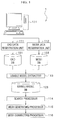
- FIG.5 is a flowchart (part1) showing the detailed procedure of usable model extraction processing according to the first embodiment.
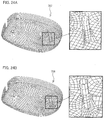
- FIG.6A and FIG.6B are figures showing an example of a mesh data which is what usable model extraction processing deals with.
- FIG.7A and FIG.7B are figures showing the T-connection edge extraction method
- FIG.8A and FIG.8B are figures showing the mesh states before and after separation.
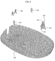
- FIG.9 is a figure showing the result of separation processing of mesh members.
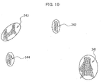
- FIG.10 is a figure showing examples of a plurality of usable mesh.
- FIG.11 is a figure (part1) showing the mesh belonging face extraction method.
- FIG.12 is a figure (part2) showing the mesh belonging face extraction method.
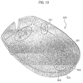
- FIG.13 is a figure (part1) showing an example of a CAD data.
- FIG.14A and FIG.14B are figures showing examples of separated CAD members.
- Usable model extraction processing is intended to search associated CAD data and mesh data registered in the CAD database 121 and the mesh database 122 (see FIG.1 for both) for usable partial shapes and to register them as usable models in the usable model database 123.
- the processing as indicated in FIG.5 is an effective method for a shell mesh.
- the usable model extractor 113 extracts an element edge (referred to as T-connection element edge hereinafter) to which three or more elements belong in the sides (referred to as element edge hereinafter) constituting elements of a mesh data.
- FIG.7A is an enlarged figure of the part of a symbol 311
- FIG.7B is an enlarged figure of the part of a symbol 312.
- FIG.6B is an enlarged figure of the vicinity of the mesh member 301 in FIG.6A .
- tow elements belong to one element edge on the same mesh member. For instance, two elements 322 and 323 belong to an element edge 321.
- three or more elements belong to one element edge.
- three elements 326 to 328 belong to an element edge 325 as shown in FIG.7B .
- the usable model extractor 113 extracts element edges (T-connection element edges) to which three or more elements belong as the element edge 325 in FIG.7B .
- Step 201 the T-connection element edges indicated by a symbol 331 or the like in FIG.6A and FIG.6B are extracted.
- the usable model extractor 113 separates mesh members by T-connection element edges.
- FIG.8A shows the mesh before separation
- FIG.8B shows the mesh after separation
- a node and an element edge in a connection point are shared by three elements.
- a node and an element in a connecting point are not shared by being in contact with each other.
- FIG.9 gives the result of Step 202.
- the mesh members 301 and 302 are seen completely separated from a mesh member 300, however, actually the mesh members 301 and 302 are separated in contact with the mesh member 300.
- the mesh members 301 and 302 have the element edges and nodes that they have being in contact with the element edges and nodes that the mesh member 300 has.
- the mesh member 301 is separated from a cylindrical mesh member 331 (a first mesh member) and an approximately triangular mesh member 332 (the first mesh member). The same is applied to the mesh member 303.
- Step 203 in FIG.5 the usable model extractor 113 moves each separated mesh member constituted by a set of elements and deletes the group including the maximum number of elements.
- the usable model extractor 113 deletes the mesh member 300 including the maximum number of elements (the largest first mesh member) in FIG.9 .
- succeeding processing may be performed not by deleting the mesh member 300 including the maximum number of elements but by removing it temporarily.
- the mesh member 300 including the determined number of elements may be deleted. This can prevent the mesh member 300 from being included in the grouping of Step 204.
- FIG.10 shows the result of the processing by Step 203 in FIG.5 .
- the usable model extractor 113 returns the mesh member separated from T-connection element edges to the original and moves again each mesh member constituted by a set of elements to generate a mesh data for a usable model in each mesh member (a mesh member grouped in Step 204 is referred to as a usable mesh).
- the usable model extractor 113 performs grouping the mesh members both of which elements are mutually contacted out of mesh members 301 to 304 in FIG. 9 to extract four usable mesh members 341 to 344 (second mesh members) in FIG.10 .
- the mesh member indicated by a symbol 301 is actually separated from the mesh member 331 and the mesh member 332.
- the usable model extractor 113 connects the mesh member 331 and the mesh member 332 (the first mesh members) both of which elements are mutually contacted and groups them to generate the usable mesh member 341 (the second mesh member). The same is applied to usable mesh members 342 to 344.
- a usable mesh can be extracted in a shell mesh without an operation by a human.
- the usable model extractor 113 arranges an extracted usable mesh member on CAD data. This processing is executed on the basis of coordinates of a usable mesh and ones of a CAD data. And, in Step 205 in FIG.5 , the usable extractor 113 draws normal lines (practically tangential planes) from at least one of internal points of each element in a usable mesh and extracts configuration faces of a CAD data intersecting with normal lines (referred to as mesh belonging faces hereinafter).
- the length of normal lines is a thickness value of an element. This thickness may be either an average value of a whole CAD or a value of a CAD data on which a usable mesh is arranged.
- Step 205 With reference to FIG.11 and FIG.12 , the processing of Step 205 will be described in details.
- FIG.11 is a schematic diagram concerning the mesh belonging face extraction method in Step 205.
- a symbol 401 indicates a usable mesh and a symbol 402 and a symbol 403 indicates configuration faces of a CAD data.
- symbols 411 and 412 indicate normal lines drawn from the usable mesh 401.
- the configuration faces 402 and 403 intersecting with the normal lines 411 and 412 of CAD data are mesh belonging faces for the usable mesh 401.
- This processing can extract configuration faces, namely, a mesh belonging faces of a CAD data corresponding to a usable mesh member.
- CAD data configuration faces intersected by normal lines firstly are only determined as mesh belonging faces, while having the length of normal lines remained infinite.
- FIG.12 is a figure showing the mesh belonging face corresponding to the usable mesh member 342 in FIG.10 .
- FIG.12 shows an example showing the usable mesh 344 of FIG.10 is arranged in the CAD member 511 of FIG.13 .
- the normal lines 431 are drawn in the same method as the one used when normal lines 411 and 412 of FIG.11 are drawn, and the lengths of the normal lines 411 and 412 are the length of the normal line 431.
- the reason that the usable mesh 344 is protruded from the CAD member 511 in FIG.13 is that the usable mesh 344 is longer than the CAD member 511 by the thickness of the CAD member 514 in FIG. 14 .
- some parts of the normal lines 431 are omitted in FIG.12 .
- the usable mode extractor 113 separates the mesh belonging face from the CAD data. Subsequently, the usable model extractor 113 performs grouping the obtained mesh belonging faces and the configuration faces connecting the mesh belonging faces (referred to as configuration faces relating to mesh belonging faces) to generate the CAD data (referred to as a usable CAD) corresponding to the usable mesh member from a CAD data.
- the configuration faces of the CAD member 514 in FIG.14A also are connected to the configuration faces of the CAD member 511, however, the CAD member 514 spreads outside the CAD member 511, thus doesn't connect the configuration faces 441 and 442 of the CAD member 511. Therefore, the configuration face of the CAD member 514 is not the configuration faces connecting the configuration faces 441 and 442.
- the usable model extractor 113 deletes a CAD data of a maximum volume.
- the group of maximum volume is a CAD member 510 in FIG.14B .
- the succeeding processing may be executed not by deleting a CAD data of a maximum volume but by removing it temporarily.
- a CAD data of a predetermined volume may be deleted.
- Step 208 in FIG.5 grouping is performed again by connecting CAD members mutually contacted.
- the cylindrical CAD member 502 and the approximately triangular CAD member 503 are recognized as different CAD members not to be connected. Therefore, the usable mode extractor 113 performs grouping so as to connect the cylindrical member 502 and the approximately triangular CAD member 503 both of which mesh belonging faces contact with each other. Consequently, the CAD member 501 is recognized as one CAD member. The same is applied to the CAD members 502 to 504.
- Symbols 511 to 514 in FIG.14A indicate the results of grouping.
- the usable mode extractor 113 designates each group generated as a result of grouping in Step 207 as a usable CAD for a usable model. Thereafter, the usable model extractor 113 registers a usable CAD and a usable mesh to which a usable CAD belongs as associated usable models in the usable model database 123. For example, the usable mesh 341 in FIG.10 and the usable CAD 511 in FIG.14A are registered as associated usable models in the usable model database 123. Likewise, the usable mesh 342 in FIG.10 and the usable CAD 512 in FIG.14A are registered as associated usable models in the usable model database 123 in FIG.10 .
- the usable mesh 343 in FIG.10 and the usable CAD 513 in FIG.14A are registered as associated usable models in the usable model database 123.
- the usable mesh 344 in FIG.10 and the usable CAD 514 in FIG.14A are registered as associated usable models in the usable model database 123.
- This processing can extract a usable CAD in a shell mesh without an operation by a human.
- processing illustrated in FIG.15 to FIG.20 can be applied into a shell mesh as well as a solid mesh (a mesh composed of hexahedrons, pentahedrons, and tetrahedrons).
- FIG.15 is a flowchart (part 2) indicating the detailed procedure of the usable model extraction processing according to the first embodiment.
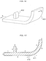
- FIG.16 is a figure showing an example of a CAD data (part 2).
- FIG.17 is a figure showing a section of a CAD data.
- FIG.18 is a figure showing an example of a graph G0.
- FIG.19 is a figure showing an example of a graph G1.
- FIG.20 is a figure showing an example of a graph G2. The graphs G0 to G2 will be described later.
- the CAD data 601 in FIG.16 has a corresponding mesh data.
- Step 304 in FIG.15 the usable mode extractor 113 generates the graph G0 in which nodes represent the configuration faces of a CAD data and edges represent the phase relations between configuration faces of a CAD data.
- FIG.17 which is a section taken along A-A of FIG.16 will be used to be easily described.
- the CAD data comprises configuration faces A to J.
- the graph G0 (a first graph) in FIG.18 shows the connection relations of respective configuration faces A to J as a graph, while representing these configuration faces A to J as nodes.
- the usable model extractor 113 will search the graph G0 for edges in which an angle between mutual tangents in a connecting part of configuration faces is threshold or smaller (for instance 165 degrees). And, in Step 302 of FIG.15 , the usable model extractor 113 generates the graph G1 (a second graph) which is left after the edges are deleted.
- an angle formed by a tangent 511 of a configuration face A and a tangent 512 of a configuration face B is 165 degrees or larger.
- the same is applied to angles formed by configuration surfaces D and E, configuration surfaces F and G, and configuration surfaces G and H.
- the usable model extractor 113 deletes the nodes and lines other than "A, B ", “D, E”, “F, G” and “G, H” in the graph G0.
- the graph obtained as a result of Step 302 is the graph G1 shown in FIG.19 .
- the deleted nodes and lines are indicated by dashed lines.
- an independent set is a set of nodes not mutually connected by edges.
- an independent set corresponds to (A,B), (D, E), and (F, G, H).
- (F, G, H) stands for a set of nodes F, G, and H here.
- a base set is an independent set of a maximum sum of areas of nodes attributed to respective independent sets extracted in Step 303.
- the independent set (A, B) having the maximum area is a base set.
- the processing is, in fact, executed for the CAD data of FIG.16 .
- an independent set of a predetermined sum of areas of nodes belonging to respective independent sets may be a base set.
- the usable model extractor 113 searches the graph G0 for nodes in which an angle formed by nodes of a base set and face normal lines is almost 180 degrees and a distance between faces is threshold or shorter. And, in Step 305 of FIG.15 , the usable model extractor 113 adds the independent set composed of the nodes obtained by searching to the base set.
- nodes in which an angle formed by nodes of a base set and face normal line is almost 180 degrees (namely, the same vector and the opposite direction) and distances between faces are threshold or shorter are the nodes facing to a base set, and distances between configuration faces corresponding to nodes are a predetermined value (thickness or the like) or shorter.
- nodes in which face normal line is almost 180 degrees and a distances between face is threshold or shorter corresponding to the node A in a base set are the nodes E and I.
- nodes in which face normal line is almost 180 degrees and a distance between faces is threshold or shorter corresponding to the node B in the base set is the node D.
- the usable model extractor 113 adds (D, E, I) to the base set in Step 305 in FIG.15 .
- Step 306 in FIG.15 the usable model extractor 113 deletes the nodes of base sets (A, B, C, D, E, I) from the graph in Step 706 to generate the graph G2 (a third graph).
- FIG.20 shows the graph G2 generated in Step 306.
- the usable model extractor 113 extracts the independent sets (F, G, H) from the graph G2.
- the face of extracted independent set is a usable CAD.
- the usable model extractor 113 searches for elements of a mesh data inside the extracted usable CAD, and designates such a set of elements as a usable mesh which is registered in the usable model database 123 as an associated data with a usable CAD.
- usable mesh and usable CAD are extracted without an operation by a human also in a solid mesh.
- the processing indicated in FIG.5 to FIG.20 enables a usable CAD and a usable mesh corresponding to the CAD member 602 to be extracted from a CAD data shown in FIG.16 without an operation by a human.
- Step 111 in FIG.3B will now be described.
- the search processor 114 searches a CAD data to be divided into meshes (a mesh generation target CAD data) for the parts (similar parts) similar to a usable CAD. For instance, the extraction processor 114 calculates a similarity mainly on the basis of the difference between the feature amount of partial shapes of the mesh generation target CAD data designated through the input and output unit 131 and the feature amount of shapes of a usable CAD.
- Such a search processing can be performed by the known techniques, for example, disclosed in Japanese Unexamined Patent Application Publication No.2007-280129 and in " Hongshen Wang, Lin Zhang and Yonggui Zhang, "Partial Matching of 3D CAD Models with Attribute Graph", Applied Mechanics and Materials, Vol.528(2014), pp.302-309 ".
- the mesh generating processor generates a mesh for parts (a non-similar part) in which no similar usable CAD haven't been found as a result of Step 111 of FIG.3B in a mesh generation target CAD data to be divided into meshes.
- the generated mesh data is referred to as a mesh member for a non-similar part (a non-similar partial mesh data).
- the mesh generating processor 115 deletes configuration faces of similar parts from the mesh generation target CAD data. Then, the mesh generating processor 115 generates a mesh for a shape composed of remaining configuration faces.
- the methods for generating mesh the techniques disclosed in Japanese Patent Application Publications No.8-138082 and No. 11-110586 can be applied.
- the shape composed of configuration faces which is what is left in a mesh generation target CAD data (a CAD data to be divided into meshes) after deleting configuration faces of similar parts has holes in the deleted similar parts.
- a normal mesh cannot be generated as it is.
- FIG.21 is a flowchart indicating the detailed procedure of the mesh generation processing according to the first embodiment.
- FIG.22 is a figure showing a mesh deformation method.
- FIG.24A and FIG.24B are figures showing a mesh connection method.
- the mesh connecting processor 116 deforms a usable mesh so as to fit to a shape of a corresponding similar part.
- This processing can be performed by the techniques disclosed, for example, in Japanese Unexamined Patent Application Publication No.2006-301753 .
- the mesh connecting processor 116 deforms a usable mesh 702 so as to fit to the CAD member 703 in Step 403. Consequently, the mesh member indicated by a symbol 704 is obtained.
- Step 402 in FIG.21 the mesh connecting processor 116 arranges a usable mesh deformed in Step 401 on mesh members of a non-similar part. Positioning is determined mainly on the basis of coordinates of a mesh generation target CAD data.
- a symbol 707 in FIG.24A shows the mesh data in which the usable mesh deformed in Step 402 is arranged on a mesh member 706 of a non-similar part in the mesh generation target CAD data 705 indicated in FIG.23 .
- the mesh connecting processor 116 connects an arranged usable mesh and a mesh member of a non-similar part.
- the mesh connecting processor 116 connects a usable mesh and a mesh member of a non-similar part by the methods (A1) and (A2) and, if necessary, combining other methods with them.
- Step 404 The processing of Step 404 is executed for a mesh data 707 in FIG.24A , so that a mesh data 708 in FIG.24B is obtained.
- Step 404 in FIG.21 the mesh connecting processor 116 improves the elements deteriorated in qualities.
- "To improve the elements deteriorated in qualities” mainly means eliminating elements reduced extremely as a result of the processing of Step 403.
- the processing of Step 404 can be performed, for example, by the technique disclosed in Japanese Unexamined Patent Application Publication No.2008-107960 .
- a mesh satisfying a specification can be generated by using parts of a mesh data which has already been used for a simulation without inputting parameters such as a mesh size and a quality. Accordingly, using parts of a mesh data which has been used for a simulation and by which it is confirmed that sufficient accuracy is obtained makes it possible to generate a new mesh succeeding the shape and quality of this mesh. Consequently, generating a mesh for similar parts of a mesh generation target CAD data becomes possible without an operation by a human, resulting in improvement of an efficiency of mesh data generation.
- FIG.25 is a figure indicating a configuration example of the analysis model creation assistance system according to a second embodiment.
- the analysis model creation assistance system includes a server 801 and a terminal device 802 mutually connected by a network.
- the terminal device 802 includes a registration data designating unit 811 for designating data files of a CAD data and a mesh data to be registered in the server 801 through an input unit not illustrated in the terminal device 802, and transmitting the data files to the server 801 through a network.
- the server 801 includes an account management unit 821 and a charging management unit 822, and an analysis model creation assistance unit 823.
- the account management unit 821 and the charging management unit 822 may be provided respectively in different devices from the server 801.
- the account management unit 821 manages an access authority and an execution authority of a user in the server 801. In other words, the account management unit 821 limits a user capable of using usable models on the basis of information input through the terminal device 802. Such limitation can enhance securities of usable models.
- the charging management unit 822 manages the transfers of advertisement and usage fees in exchange for usage of the analysis model creation assistance system 800 and a registration of usable models.
- analysis model creation assistance unit 823 has the same configuration as the analysis model creation assistance device 1 in FIG.1 , the description will be omitted here. Such managements enable the present invention to be applied into business.
- the account management unit 821, the charging management unit 822, and the analysis model creation assistance unit 823 are embodied respectively, when programs stored in the storage 103 are developed in the storage 101 and executed by the CPU 102.
- a system as shown in a FIG.25 can provide the following business method.
- a manufacturer A creates a CAD data.
- an outsourcer B creates a mesh data corresponding to the CAD data created by the manufacture A.
- the manufacture A and the outsourcer B registers the CAD data and the mesh data in the CAD database 121 and the mesh database 122 in the server 801 through the registration data designating unit 811 in the terminal device 802 possessed by the manufacture A and the outsourcer B respectively.
- the manufacture A may designate users and companies allowed to access to the mesh data registered by the outsourcer B
- the analysis model creation assistance unit 823 in the server 801 generates a usable mesh and a usable CAD on the basis of a registered CAD data and a mesh data.
- the outsourcer B can receive a consideration for usage of registering a usable model as well as a consideration for mesh creation.
- a supplier C supplying the manufacture A with members not only supplies members but also registers a CAD data and a mesh data of supplied members in the CAD database 121 and the mesh database 122 in the server 801 through the registration data designating unit 811.Consequently, it is not necessary for the manufacture A to create a mesh of such a member, while the supplier C receives a consideration for registration of the CAD data and the mesh data of the supplied members.
- a mesh data can be shared among companies. Since a CAD data and a mesh data are not only shared as they are but also registered as extracted usable models, sharing while the know-how is concealed is achieved. This can be applied to business, too.
- the present embodiment is assumed to employ a mesh data used mainly for a finite element method, however replacing a mesh by elements such as a pixel and a polygon will enable the present embodiment to be applied into a two-dimensional image and a three-dimensional image.
- the present invention is not limited to the above embodiments but includes various versions.
- the above embodiments are detailed descriptions to give clear descriptions of the present invention, which is not necessarily limited to all of the configurations described.
- a part of configuration in one embodiment can be replaced with a configuration of the other embodiment, and also a configuration of one embodiment can be added to a configuration of the other embodiment.
- addition of, deletion of, and replacement with the other configurations can be performed.
- the above respective configurations, functions, the respective parts 111 to 116, 811, 821, 822, and the respective databases 121 to 123 or the like may be achieved in a hardware, for example, in such a way that some or all of them are designed with integrated circuits. Additionally, as shown in FIG.2 , the above respective configurations and functions or the like may be achieved in software in such a way that processors such as the CPU 102 interpret and run programs realizing the respective functions. Information such as programs, tables, and files to the respective functions can be stored in recording mediums such as a memory and a SSD (Solid State Drive), IC (Integrated Circuit), SD (Secure Digital) card, and DVD (Digital Versatile Disc) besides HD.
- SSD Solid State Drive
- IC Integrated Circuit
- SD Secure Digital
- DVD Digital Versatile Disc
- control lines and information lines necessary for descriptions are shown, thus all control lines and information lines are not necessarily shown on a product. It may be assumed that almost all of the configurations are connected with each other practically.
Landscapes
- Engineering & Computer Science (AREA)
- Physics & Mathematics (AREA)
- Theoretical Computer Science (AREA)
- General Physics & Mathematics (AREA)
- Software Systems (AREA)
- Computer Graphics (AREA)
- Geometry (AREA)
- Computer Hardware Design (AREA)
- General Engineering & Computer Science (AREA)
- Computer Vision & Pattern Recognition (AREA)
- Architecture (AREA)
- Evolutionary Computation (AREA)
- Management, Administration, Business Operations System, And Electronic Commerce (AREA)
Applications Claiming Priority (1)
| Application Number | Priority Date | Filing Date | Title |
|---|---|---|---|
| JP2015118405A JP2017004305A (ja) | 2015-06-11 | 2015-06-11 | 解析モデル作成支援システム、解析モデル作成支援装置及び解析モデル作成支援プログラム |
Publications (1)
| Publication Number | Publication Date |
|---|---|
| EP3104335A1 true EP3104335A1 (fr) | 2016-12-14 |
Family
ID=56117609
Family Applications (1)
| Application Number | Title | Priority Date | Filing Date |
|---|---|---|---|
| EP16173846.3A Withdrawn EP3104335A1 (fr) | 2015-06-11 | 2016-06-10 | Système d'assistance à la création d'un modèle d'analyse, dispositif d'assistance à la création d'un modèle d'analyse et programme d'assistance à la création de modèle d'analyse |
Country Status (3)
| Country | Link |
|---|---|
| US (1) | US20160364908A1 (fr) |
| EP (1) | EP3104335A1 (fr) |
| JP (1) | JP2017004305A (fr) |
Cited By (2)
| Publication number | Priority date | Publication date | Assignee | Title |
|---|---|---|---|---|
| CN109979020A (zh) * | 2019-04-04 | 2019-07-05 | 广州视源电子科技股份有限公司 | 一种线段吸附方法、装置、设备及存储介质 |
| CN113255058A (zh) * | 2021-05-25 | 2021-08-13 | 星河动力(北京)空间科技有限公司 | 运载火箭的有限元模型的处理方法、装置、设备及存储介质 |
Families Citing this family (2)
| Publication number | Priority date | Publication date | Assignee | Title |
|---|---|---|---|---|
| US10861233B1 (en) * | 2019-07-17 | 2020-12-08 | Pixar | Mesh wrap based on affine-invariant coordinates |
| CN116187146B (zh) * | 2023-04-28 | 2023-07-21 | 四川旷谷信息工程有限公司 | 一种工程结构有限元分析方法、装置、设备及存储介质 |
Citations (7)
| Publication number | Priority date | Publication date | Assignee | Title |
|---|---|---|---|---|
| JPH08138082A (ja) | 1994-11-07 | 1996-05-31 | Internatl Business Mach Corp <Ibm> | 四角形メッシュの生成方法及びシステム |
| JPH11110586A (ja) | 1997-09-05 | 1999-04-23 | Internatl Business Mach Corp <Ibm> | メッシング方法及びコンピュータ |
| JP2006301753A (ja) | 2005-04-18 | 2006-11-02 | Hitachi Ltd | 解析モデル作成システム |
| JP2007122205A (ja) | 2005-10-26 | 2007-05-17 | Hitachi Ltd | 解析用モデル作成支援システム |
| JP2007280129A (ja) | 2006-04-07 | 2007-10-25 | Hitachi Ltd | 類似形状検索装置、類似形状検索方法及びプログラム |
| JP2008107960A (ja) | 2006-10-24 | 2008-05-08 | Hitachi Ltd | 解析用メッシュ生成装置 |
| US20090271156A1 (en) * | 2008-04-28 | 2009-10-29 | Canon Kabushiki Kaisha | Apparatus and method for generating analysis model |
Family Cites Families (4)
| Publication number | Priority date | Publication date | Assignee | Title |
|---|---|---|---|---|
| US20150187130A1 (en) * | 2011-02-10 | 2015-07-02 | Google Inc. | Automatic Generation of 2.5D Extruded Polygons from Full 3D Models |
| WO2013019961A2 (fr) * | 2011-08-02 | 2013-02-07 | Design Play Technologies Inc. | Plateforme de conception collaborative en temps réel |
| EP2905744A1 (fr) * | 2014-02-05 | 2015-08-12 | Fujitsu Limited | Amélioration de la qualité de maille en ingénierie assistée par ordinateur |
| US9734264B2 (en) * | 2014-05-05 | 2017-08-15 | Microsoft Technology Licensing, Llc | Fabricating three-dimensional objects with embossing |
-
2015
- 2015-06-11 JP JP2015118405A patent/JP2017004305A/ja active Pending
-
2016
- 2016-06-10 US US15/179,344 patent/US20160364908A1/en not_active Abandoned
- 2016-06-10 EP EP16173846.3A patent/EP3104335A1/fr not_active Withdrawn
Patent Citations (7)
| Publication number | Priority date | Publication date | Assignee | Title |
|---|---|---|---|---|
| JPH08138082A (ja) | 1994-11-07 | 1996-05-31 | Internatl Business Mach Corp <Ibm> | 四角形メッシュの生成方法及びシステム |
| JPH11110586A (ja) | 1997-09-05 | 1999-04-23 | Internatl Business Mach Corp <Ibm> | メッシング方法及びコンピュータ |
| JP2006301753A (ja) | 2005-04-18 | 2006-11-02 | Hitachi Ltd | 解析モデル作成システム |
| JP2007122205A (ja) | 2005-10-26 | 2007-05-17 | Hitachi Ltd | 解析用モデル作成支援システム |
| JP2007280129A (ja) | 2006-04-07 | 2007-10-25 | Hitachi Ltd | 類似形状検索装置、類似形状検索方法及びプログラム |
| JP2008107960A (ja) | 2006-10-24 | 2008-05-08 | Hitachi Ltd | 解析用メッシュ生成装置 |
| US20090271156A1 (en) * | 2008-04-28 | 2009-10-29 | Canon Kabushiki Kaisha | Apparatus and method for generating analysis model |
Non-Patent Citations (4)
| Title |
|---|
| ARIEL SHAMIR: "Segmentation and Shape Extraction of 3D Boundary Meshes", EUROGRAPHICS 2006; STAR - STATE OF THE ART REPORT, 2006, pages 1 - 13, XP002762142, Retrieved from the Internet <URL:ftp://ftp.idc.ac.il/Faculty/arik/ShamirPapers/SegmentSTAR.pdf> [retrieved on 20160921] * |
| HONGSHEN WANG; LIN ZHANG; YONGGUI ZHANG: "Partial Matching of 3D CAD Models with Attribute Graph", APPLIED MECHANICS AND MATERIALS, vol. 528, 2014, pages 302 - 309 |
| LEE Y-G ET AL: "SHELL MESH GENERATION BY MEDIAL AXIS TRANSFORMATION", COMPUTERS IN ENGINEERING AND PROCEEDINGS OF THE DATABASESYMPOSIUM, XX, XX, 1 January 1995 (1995-01-01), pages 713 - 727, XP001004772 * |
| TANIMOTO; NAKAMURA; TAKEI: "Creation of a filling-hole surface by using CAE simulation", PROCEEDINGS OF THE JAPAN SOCIETY FOR PRECISION ENGINEERING, 2010, pages 133 - 134 |
Cited By (3)
| Publication number | Priority date | Publication date | Assignee | Title |
|---|---|---|---|---|
| CN109979020A (zh) * | 2019-04-04 | 2019-07-05 | 广州视源电子科技股份有限公司 | 一种线段吸附方法、装置、设备及存储介质 |
| CN113255058A (zh) * | 2021-05-25 | 2021-08-13 | 星河动力(北京)空间科技有限公司 | 运载火箭的有限元模型的处理方法、装置、设备及存储介质 |
| CN113255058B (zh) * | 2021-05-25 | 2021-10-22 | 星河动力(北京)空间科技有限公司 | 运载火箭的有限元模型的处理方法、装置、设备及存储介质 |
Also Published As
| Publication number | Publication date |
|---|---|
| JP2017004305A (ja) | 2017-01-05 |
| US20160364908A1 (en) | 2016-12-15 |
Similar Documents
| Publication | Publication Date | Title |
|---|---|---|
| US9208278B2 (en) | Clustering using N-dimensional placement | |
| Danglade et al. | On the use of machine learning to defeature CAD models for simulation | |
| CN107545025B (zh) | 利用形态学标准查询数据库 | |
| US20190065913A1 (en) | Search method and information processing apparatus | |
| Xiao et al. | Mobile 3D assembly process information construction and transfer to the assembly station of complex products | |
| Giri et al. | Generating complete disassembly sequences by utilising two-dimensional views | |
| US20160364908A1 (en) | Analysis Model Creation Assistance System, Analysis Model Creation Assistance Device and Analysis Model Creation Assistance Program | |
| Thomas et al. | Detecting symmetry in scalar fields using augmented extremum graphs | |
| Kwon et al. | User-assisted integrated method for controlling level of detail of large-scale B-rep assembly models | |
| CN107567641B (zh) | 用于识别复制品的系统和方法 | |
| EP4071650A2 (fr) | Techniques d'alignement de graphe pour dessins à dimensionnement automatique | |
| Li et al. | Sketch-based 3D modeling by aligning outlines of an image | |
| EP3432171B1 (fr) | Dispositif d'aide à la création de modèle d'analyse et procédé d'aide à la création de modèle d'analyse | |
| Lai et al. | Recognition and decomposition of rib features in thin-shell plastic parts for finite element analysis | |
| CN120821865A (zh) | 局部拓扑相似度检索的方法、程序、存储介质和计算机 | |
| WO2015019458A1 (fr) | Dispositif d'extraction de solution, procédé d'extraction de solution, et programme d'extraction de solution | |
| Xia et al. | A fast and automatic hole-filling method based on feature line recovery | |
| Kulkarni et al. | Leveraging feature information for defeaturing sheet metal feature-based CAD part model | |
| JP7084894B2 (ja) | リソース管理システム、リソース割当方法 | |
| US20170132174A1 (en) | Novel method for the fast derivation of delaunay tesselations | |
| JP5229161B2 (ja) | 情報提供装置、情報提供方法および情報提供プログラム | |
| Bonaventura et al. | 3D shape retrieval using viewpoint information‐theoretic measures | |
| Onosato et al. | Weaving a four-dimensional mesh model from a series of three-dimensional voxel models | |
| Lin et al. | CD-graph: planar graph representation for spatial adjacency and neighbourhood relation with constraints | |
| Obermaier et al. | Volume Deformations in Grid‐Less Flow Simulations |
Legal Events
| Date | Code | Title | Description |
|---|---|---|---|
| PUAI | Public reference made under article 153(3) epc to a published international application that has entered the european phase |
Free format text: ORIGINAL CODE: 0009012 |
|
| STAA | Information on the status of an ep patent application or granted ep patent |
Free format text: STATUS: REQUEST FOR EXAMINATION WAS MADE |
|
| 17P | Request for examination filed |
Effective date: 20160805 |
|
| AK | Designated contracting states |
Kind code of ref document: A1 Designated state(s): AL AT BE BG CH CY CZ DE DK EE ES FI FR GB GR HR HU IE IS IT LI LT LU LV MC MK MT NL NO PL PT RO RS SE SI SK SM TR |
|
| AX | Request for extension of the european patent |
Extension state: BA ME |
|
| RIN1 | Information on inventor provided before grant (corrected) |
Inventor name: KONGO, CHIKARA Inventor name: ONODERA, MAKOTO Inventor name: TSUKAMOTO, MAMORU Inventor name: SHINTANI, MASAKI Inventor name: HARIYA, MASAYUKI Inventor name: EGUCHI, HISAYUKI Inventor name: UTSUNOMIYA, TOMOAKI Inventor name: HIRO, YOSHIMITSU |
|
| STAA | Information on the status of an ep patent application or granted ep patent |
Free format text: STATUS: THE APPLICATION HAS BEEN WITHDRAWN |
|
| 18W | Application withdrawn |
Effective date: 20180518 |