EP3104351A1 - System und verfahren zum auffinden von vorrichtungen in vorbestimmten räumen - Google Patents
System und verfahren zum auffinden von vorrichtungen in vorbestimmten räumen Download PDFInfo
- Publication number
- EP3104351A1 EP3104351A1 EP16171830.9A EP16171830A EP3104351A1 EP 3104351 A1 EP3104351 A1 EP 3104351A1 EP 16171830 A EP16171830 A EP 16171830A EP 3104351 A1 EP3104351 A1 EP 3104351A1
- Authority
- EP
- European Patent Office
- Prior art keywords
- members
- devices
- location
- control element
- units
- Prior art date
- Legal status (The legal status is an assumption and is not a legal conclusion. Google has not performed a legal analysis and makes no representation as to the accuracy of the status listed.)
- Withdrawn
Links
Images


Classifications
-
- H—ELECTRICITY
- H04—ELECTRIC COMMUNICATION TECHNIQUE
- H04W—WIRELESS COMMUNICATION NETWORKS
- H04W4/00—Services specially adapted for wireless communication networks; Facilities therefor
- H04W4/02—Services making use of location information
- H04W4/023—Services making use of location information using mutual or relative location information between multiple location based services [LBS] targets or of distance thresholds
-
- H—ELECTRICITY
- H04—ELECTRIC COMMUNICATION TECHNIQUE
- H04W—WIRELESS COMMUNICATION NETWORKS
- H04W4/00—Services specially adapted for wireless communication networks; Facilities therefor
- H04W4/02—Services making use of location information
- H04W4/029—Location-based management or tracking services
-
- G—PHYSICS
- G01—MEASURING; TESTING
- G01S—RADIO DIRECTION-FINDING; RADIO NAVIGATION; DETERMINING DISTANCE OR VELOCITY BY USE OF RADIO WAVES; LOCATING OR PRESENCE-DETECTING BY USE OF THE REFLECTION OR RERADIATION OF RADIO WAVES; ANALOGOUS ARRANGEMENTS USING OTHER WAVES
- G01S5/00—Position-fixing by co-ordinating two or more direction or position line determinations; Position-fixing by co-ordinating two or more distance determinations
- G01S5/0009—Transmission of position information to remote stations
- G01S5/0045—Transmission from base station to mobile station
- G01S5/0054—Transmission from base station to mobile station of actual mobile position, i.e. position calculation on base station
-
- G—PHYSICS
- G01—MEASURING; TESTING
- G01S—RADIO DIRECTION-FINDING; RADIO NAVIGATION; DETERMINING DISTANCE OR VELOCITY BY USE OF RADIO WAVES; LOCATING OR PRESENCE-DETECTING BY USE OF THE REFLECTION OR RERADIATION OF RADIO WAVES; ANALOGOUS ARRANGEMENTS USING OTHER WAVES
- G01S5/00—Position-fixing by co-ordinating two or more direction or position line determinations; Position-fixing by co-ordinating two or more distance determinations
- G01S5/0009—Transmission of position information to remote stations
- G01S5/0081—Transmission between base stations
-
- G—PHYSICS
- G01—MEASURING; TESTING
- G01S—RADIO DIRECTION-FINDING; RADIO NAVIGATION; DETERMINING DISTANCE OR VELOCITY BY USE OF RADIO WAVES; LOCATING OR PRESENCE-DETECTING BY USE OF THE REFLECTION OR RERADIATION OF RADIO WAVES; ANALOGOUS ARRANGEMENTS USING OTHER WAVES
- G01S5/00—Position-fixing by co-ordinating two or more direction or position line determinations; Position-fixing by co-ordinating two or more distance determinations
- G01S5/18—Position-fixing by co-ordinating two or more direction or position line determinations; Position-fixing by co-ordinating two or more distance determinations using ultrasonic, sonic or infrasonic waves
- G01S5/30—Determining absolute distances from a plurality of spaced points of known location
-
- G—PHYSICS
- G08—SIGNALLING
- G08B—SIGNALLING SYSTEMS, e.g. PERSONAL CALLING SYSTEMS; ORDER TELEGRAPHS; ALARM SYSTEMS
- G08B21/00—Alarms responsive to a single specified undesired or abnormal condition and not otherwise provided for
- G08B21/02—Alarms for ensuring the safety of persons
- G08B21/0202—Child monitoring systems using a transmitter-receiver system carried by the parent and the child
- G08B21/0272—System arrangements wherein the object is to detect exact location of child or item using triangulation other than GPS
-
- G—PHYSICS
- G08—SIGNALLING
- G08B—SIGNALLING SYSTEMS, e.g. PERSONAL CALLING SYSTEMS; ORDER TELEGRAPHS; ALARM SYSTEMS
- G08B21/00—Alarms responsive to a single specified undesired or abnormal condition and not otherwise provided for
- G08B21/18—Status alarms
- G08B21/24—Reminder alarms, e.g. anti-loss alarms
-
- H—ELECTRICITY
- H04—ELECTRIC COMMUNICATION TECHNIQUE
- H04L—TRANSMISSION OF DIGITAL INFORMATION, e.g. TELEGRAPHIC COMMUNICATION
- H04L67/00—Network arrangements or protocols for supporting network services or applications
- H04L67/50—Network services
- H04L67/52—Network services specially adapted for the location of the user terminal
-
- H—ELECTRICITY
- H04—ELECTRIC COMMUNICATION TECHNIQUE
- H04W—WIRELESS COMMUNICATION NETWORKS
- H04W4/00—Services specially adapted for wireless communication networks; Facilities therefor
- H04W4/02—Services making use of location information
- H04W4/025—Services making use of location information using location based information parameters
-
- G—PHYSICS
- G01—MEASURING; TESTING
- G01S—RADIO DIRECTION-FINDING; RADIO NAVIGATION; DETERMINING DISTANCE OR VELOCITY BY USE OF RADIO WAVES; LOCATING OR PRESENCE-DETECTING BY USE OF THE REFLECTION OR RERADIATION OF RADIO WAVES; ANALOGOUS ARRANGEMENTS USING OTHER WAVES
- G01S11/00—Systems for determining distance or velocity not using reflection or reradiation
- G01S11/16—Systems for determining distance or velocity not using reflection or reradiation using difference in transit time between electrical and acoustic signals
Definitions
- the application pertains to identification of the location of movable objects in a predetermined region. More particularly, the application pertains to identification systems and methods having a fixed set of devices, whose location is known, and movable units. The movable units interact with the fixed devices and provide position indicating information to those devices.
- Home security systems typically employ sensors at entry points, such as windows and doors, along with interior sensors such as motion detectors, vibration sensors, shock sensors, and glass break sensors.
- misplacing devices/items of interest for example, keyfobs, mobile phones, locker keys and the like.
- a mobile phone misplaced for more than an hour can be used to transfer money from a wallet or reset the phone fully so that it cannot be identified.
- RF fobs if lost, can allow intrusion with valid access to unwanted users. It would then be difficult to avoid such a theft. The occurrence might only be realized much later about the incident.
- Bank offices are commercial premises which have a lot of objects, such as cash or bonds, that have to be safe guarded. Also, the location of people within the bank premises might be important. Only after a theft happens are asset losses realized. At that time, the perpetrators might be identified using video surveillance records.
- GPS systems for locating people if they are carrying handheld devices. But it is still not possible to locate any items of interest within the premises if GPS signals cannot reach the interior locations. And to accurately identify location of devices within premises is still not easily achieved.
- the system and method hereof intend to solve the problem of identifying the location of devices within the premises and also to track the movement of items/objects of interest.
- the solution is low cost since it does not use GPS tracking devices nor does it require a lot of sensors.
- At least two different types of devices, or units interact with one another to generate electrical signals which can be transmitted to determination circuitry. That circuitry can use the received information to establish the position of movable units relative to fixed devices in a predetermined region of interest.
- devices can be fixedly positioned in the region of interest.
- the devices are each able to transmit and receive the RF and/or sound signals from movable units and process the data.
- Position data can be transmitted to a control panel, or, central unit for further processing.
- the units are small, and movable, like a tag, which can, in one embodiment, emit RF signals, and sound signals at the same time.
- the unit can emit and/or receive for higher accuracy in position identification and configuration. These signals are to be received by the devices which can process and/or send them to the control unit for further processing. In another aspect, the system processes these signals to locate the units which are attached to an item of interest.
- multiple devices are pre-installed and are waiting to receive signals from the units. All these devices are calibrated/preprogrammed to send the position data of their own location to the control, or, central unit to locate and identify those devices.
- a unit can each be fixed or attached to an asset to be tracked/identified or it can be part of the asset.
- Units emit RF and/or sound signals which are decoded and understood by receiving devices.
- the units are capable of receiving and transmitting RF/sound signals to be used for relative tracking of units.
- the location data from the units including signal strength, sound level, difference between sound and RF timing is processed internally by the device(s) and transmitted back to the central control unit, or ,panel for further processing.
- the central unit, or, panel further processes these inputs from multiple device inputs to identify the location of the units.
- Type-A devices are installed in a premises or region of interest, and in each partition/room. These Type-A devices can be powered by a security system or self-powered. They are capable of sending information to the control panel or a central unit of the system wirelessly or via a wired medium.
- each of the devices is measured and identified using a 3D axis location measurement system. This enables the control panel to locate the Type-A devices. Once the location of Type-A devices is determined, each of the Type-A devices is calibrated/preprogrammed to send location information based on their relative location within the premises to the control unit.
- a Type-B unit which is capable of sending sound, audible or ultrasonic, and RF signals to the Type-A devices is placed between these devices for calibration. Based on the signals received from the test device, various locations within the partition/room or relevant region can be identified and mapped by the control unit, or, panel automatically. Once the panel and Type-A devices are calibrated, the system is ready to identify the location of any registered Type-B unit.
- Type-B devices are able to send/receive sound and RF signals, they are able to send relative locations with respect to another Type-B device whose location is already identified by the panel.
- Type-A devices receive additional positional information from Type-B devices and central panel can do more accurate calculations for determining position.
- the RF and sound signals can include encoded data to differentiate various Type-B units which are emitting similar signals.
- the Type-B unit(s) is/are then registered with the control unit, or, security panel and one may attach the Type-B units to items of interest.
- These units are low power, battery operated devices. Such units transmit RF and sound signals periodically, as programmed, to devices. They can send the location of the attached respective item.
- the security system devices receive such signals and send the information back to the security panel.
- the security system calculates the location of various units in the region by an automatic, at least in part circuit implemented, triangulation process.
- Type-B devices are able to locate their current location from Type-A devices and store in permanent memory.
- Type-B devices are capable of broadcasting periodically its location information and able to receive such information if instructed. Most of the time, Type-B devices ignore the broadcast messages from its peers until instructed to echo back to Type-A.
- Control panel/central unit can process all the echoed broadcast messages on need basis to improve the accuracy of location information.
- a user can determine the location of an object within the premises, using a mobile app connected to the security panel.
- the panel can triangulate the location and identify the position of the object in a user readable, or viewable format.
- the animated location information within the building can be visually presented.
- the mobile application can display the location by moving the camera to that location and streaming the image/video to the user's phone via a mobile app.
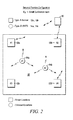
- Figs.1-3 illustrate aspects of embodiments as discussed above.
- Fig. 1A illustrates a symbol of a system control unit or control panel 10.
- Fig. 1B illustrates a symbol of a Type-A device, such as 12a illustrated therein.
- a region R1, or R2 of interest can be populated with a plurality 12a, 12b, 12c...12m of the fixed devices such as device 12a.
- Fig. 1C illustrates symbols of movable Type-B units, such as 14a, 14b.
- Type-A devices are fixedly installed in a respective region.
- the control unit 10 communicates therewith and has a record of the fixed locations thereof.
- Type-B units are mobile and readily moved in the respective region. The Type-B units could be affixed to or incorporated into an article of interest.
- Fig 2 illustrates devices 12i and a typical configuration in a secured premises such as region R1. Capabilities of each device are illustrated in Fig. 1B .
- Each security device 12i is equipped with sensors to identify location. These devices are located by the installer using a GPS system to provide location of the respective detector, such as 12i, with respect to a reference. Also this data can be connected to a building information model (BIM) if available.
- BIM building information model
- detector 12i locations relative to each other is determined in learning Sensor phase 2.
- devices such as 12i
- transmit RF and sound information which other deices 12i receive to understand the location of near-by devices.
- This phase primarily identifies the nearness of one device relative to another device in the region of interest.
- Fig 3 illustrates a triangulation mechanism of locating Type-A devices relative to each other.
- the diagram depicts movement of a Type-A device within the premises and its recalibration. In this way the central unit 10 builds a relation among sensors and their nearness to each other.
- Phase 3 device learning This is to identify the amount of noise exiting in the surrounding area and to adjust the references to identify the amount of noise to be removed.
- a test verification is carried out using a Test Type-B unit.
- the Type-A devices and Type-B units emit chirp-type signals along with RF signals which are used for synchronization and also to send the serial no of the Type-B units.
- the Type-B unit is moved around within the premises where Type-A devices have been calibrated. These Type-A devices receive the signals (both Audio and RF) from the test unit, and, send the data to central 10 unit for further processing.
- the control panel 10 sends the location information back to 14a through one of 12a, 12b or 12c.
- the Type-B unit 14a stores the location information and broadcasts message 14-1 when directed to do so.
- the Type-A devices such as 12a, 12b, 12c or 12d, obtain an initial location for unit 14b. Additionally, unit 14a receives a broad cast message 14-2 from the unit 14b.
- the control panel 10 In response to a location request from a user, the control panel 10 identifies R1 as a region of interest and instructs the Type-B units such as 14a, 14b to echo the received broadcast messages from their respective vicinity. The panel 10 can then process all of the echo messages from R1 and determine an accurate position.
- Type-B units 14i are able to determine their current locations from the Type-A devices, such as 12i. Also the Type-B units 14i are capable of periodically broadcasting their respective location information and are able to receive such information if directed to do so. In one mode of operation, the Type-B units 14i can ignore the broadcast messages from their peers until instructed to echo back to the Type-A devices, such as 12i. The panel 10 can process all of the echoed broadcast messages on a need to know basis to improve the accuracy of location information.
- the Type-A devices and Type-B units use chirp-type signals for audio. These sound signals can be sent multiple times and also can be emitted with various sounding patterns or encoded data. These patterns help differentiate one object to be identified from the other. Also the devices can be programmed to transmit the degree that the amplitude of the sound exceeds that of the RF data. This device ID can then be used to represent the object of interest such as a keychain or mobile phone or a Vault locker.
- the Type-A devices are capable of processing multipath sound signals using standard methods as would be known to those of skill in the art, and need not be discussed further. This is to ensure that the sound phenomena such as echo can be utilized to identify the location of Type-B device.
- the Type-B unit 14i is attached to a mobile phone.
- This unit is provided with an identification number which can be easily understood by the central unit 10.
- the mobile phone attached with this unit 14i is in the premises, for example R1, or R2 it periodically transmits RF and sound signals.
- the devices When mobile phone is at a fixed location, the devices, such as 12i, receive the signal strength and only nearby RF sensors receive the RF signal data. Based on a probabilistic approach the area within which the mobile is present is located. From the sound signals, the distance between each device which received the sound signal can be analyzed. Using a combination of such multiple inputs and processing the same at central unit 10, we can determine the object's location.
- the mobile phone location was recorded by central unit when it was fixed. When it is moving, the RF and sound signals will be received by different devices 12i. This information is fed to central unit 10 which processes and tracks the movement of such devices. If the object is inside a room or closet where sound attenuation level is high, this is detected by sound attenuation level and based on the mapping of opaque areas, and RF signal received, the object can be identified to be within one of the rooms or closets in a given area.
Landscapes
- Engineering & Computer Science (AREA)
- Physics & Mathematics (AREA)
- General Physics & Mathematics (AREA)
- Radar, Positioning & Navigation (AREA)
- Remote Sensing (AREA)
- Child & Adolescent Psychology (AREA)
- Emergency Management (AREA)
- Health & Medical Sciences (AREA)
- Business, Economics & Management (AREA)
- General Health & Medical Sciences (AREA)
- Computer Networks & Wireless Communication (AREA)
- Signal Processing (AREA)
- Measurement Of Velocity Or Position Using Acoustic Or Ultrasonic Waves (AREA)
- Position Fixing By Use Of Radio Waves (AREA)
- Burglar Alarm Systems (AREA)
- Mobile Radio Communication Systems (AREA)
Applications Claiming Priority (1)
| Application Number | Priority Date | Filing Date | Title |
|---|---|---|---|
| US14/736,502 US9743252B2 (en) | 2015-06-11 | 2015-06-11 | System and method for locating devices in predetermined premises |
Publications (1)
| Publication Number | Publication Date |
|---|---|
| EP3104351A1 true EP3104351A1 (de) | 2016-12-14 |
Family
ID=56081428
Family Applications (1)
| Application Number | Title | Priority Date | Filing Date |
|---|---|---|---|
| EP16171830.9A Withdrawn EP3104351A1 (de) | 2015-06-11 | 2016-05-27 | System und verfahren zum auffinden von vorrichtungen in vorbestimmten räumen |
Country Status (4)
| Country | Link |
|---|---|
| US (1) | US9743252B2 (de) |
| EP (1) | EP3104351A1 (de) |
| CN (1) | CN106257892A (de) |
| CA (1) | CA2931909A1 (de) |
Families Citing this family (4)
| Publication number | Priority date | Publication date | Assignee | Title |
|---|---|---|---|---|
| US10623680B1 (en) * | 2017-07-11 | 2020-04-14 | Equinix, Inc. | Data center viewing system |
| CN110363865A (zh) * | 2019-05-31 | 2019-10-22 | 成都科旭电子有限责任公司 | 基于bim和物联网的智慧银行监控系统 |
| CN111060875B (zh) * | 2019-12-12 | 2022-07-15 | 北京声智科技有限公司 | 设备相对位置信息获取方法、装置及存储介质 |
| WO2022224062A1 (en) * | 2021-04-19 | 2022-10-27 | 3M Innovative Properties Company | Audio identification system for personal protective equipment |
Citations (6)
| Publication number | Priority date | Publication date | Assignee | Title |
|---|---|---|---|---|
| WO1997050065A1 (en) * | 1996-06-26 | 1997-12-31 | Par Government Systems Corporation | Sensing with active electronic tags |
| US20070205886A1 (en) * | 2006-03-01 | 2007-09-06 | Huseth Steve D | RF/acoustic person locator system |
| US20090190441A1 (en) * | 2008-01-29 | 2009-07-30 | Nec (China) Co., Ltd. | Autonomous ultrasonic indoor tracking system |
| US20110260859A1 (en) * | 2010-04-27 | 2011-10-27 | Mgm Computer Systems, Inc. | Indoor and outdoor security system and method of use |
| US20110306370A1 (en) * | 2010-06-09 | 2011-12-15 | Nec (China) Co., Ltd. | Receiver system, method for arranging the receiver system and positioning system comprising the receiver system |
| US8094012B1 (en) * | 2009-05-15 | 2012-01-10 | The United States Of America As Represented By The Secretary Of The Navy | Active composite RFID tag for object localization and instruction |
Family Cites Families (9)
| Publication number | Priority date | Publication date | Assignee | Title |
|---|---|---|---|---|
| US7695335B2 (en) * | 2005-06-06 | 2010-04-13 | Logeon Spec Ops, Inc. | Marine locator device |
| WO2009038797A2 (en) * | 2007-09-20 | 2009-03-26 | Evolution Robotics | Robotic game systems and methods |
| CN101718859A (zh) * | 2008-10-09 | 2010-06-02 | 日电(中国)有限公司 | 以自适应分辨率定位目标的方法和系统 |
| EP2663359B1 (de) * | 2011-01-16 | 2017-11-01 | Q-Core Medical Ltd. | Verfahren, vorrichtung und systeme zur kommunikation mit medizinischen vorrichtungen sowie zu deren steuerung und lokalisierung |
| WO2014089040A1 (en) * | 2012-12-03 | 2014-06-12 | University Of Florida Research Foundation, Inc. | Apparatus, method, and software systems for smartphone-based fine-grained indoor localization |
| US20140273857A1 (en) * | 2013-03-13 | 2014-09-18 | Optio Labs, Inc. | Systems and methods to secure short-range proximity signals |
| ITBA20130065A1 (it) * | 2013-10-02 | 2015-04-03 | Domenico Colucci | Sistema di localizzazione "indoor" ad alta affidabilita' e relative metodologie di utilizzo |
| US9912594B2 (en) * | 2014-06-10 | 2018-03-06 | Google Llc | Probabilistic message filtering and grouping |
| US9609474B2 (en) * | 2015-02-04 | 2017-03-28 | Alcatel Lucent | Localization using a wireless tag supporting multiple states |
-
2015
- 2015-06-11 US US14/736,502 patent/US9743252B2/en active Active
-
2016
- 2016-05-27 EP EP16171830.9A patent/EP3104351A1/de not_active Withdrawn
- 2016-06-01 CA CA2931909A patent/CA2931909A1/en not_active Abandoned
- 2016-06-10 CN CN201610596576.8A patent/CN106257892A/zh active Pending
Patent Citations (6)
| Publication number | Priority date | Publication date | Assignee | Title |
|---|---|---|---|---|
| WO1997050065A1 (en) * | 1996-06-26 | 1997-12-31 | Par Government Systems Corporation | Sensing with active electronic tags |
| US20070205886A1 (en) * | 2006-03-01 | 2007-09-06 | Huseth Steve D | RF/acoustic person locator system |
| US20090190441A1 (en) * | 2008-01-29 | 2009-07-30 | Nec (China) Co., Ltd. | Autonomous ultrasonic indoor tracking system |
| US8094012B1 (en) * | 2009-05-15 | 2012-01-10 | The United States Of America As Represented By The Secretary Of The Navy | Active composite RFID tag for object localization and instruction |
| US20110260859A1 (en) * | 2010-04-27 | 2011-10-27 | Mgm Computer Systems, Inc. | Indoor and outdoor security system and method of use |
| US20110306370A1 (en) * | 2010-06-09 | 2011-12-15 | Nec (China) Co., Ltd. | Receiver system, method for arranging the receiver system and positioning system comprising the receiver system |
Also Published As
| Publication number | Publication date |
|---|---|
| US9743252B2 (en) | 2017-08-22 |
| CA2931909A1 (en) | 2016-12-11 |
| US20160366562A1 (en) | 2016-12-15 |
| CN106257892A (zh) | 2016-12-28 |
Similar Documents
| Publication | Publication Date | Title |
|---|---|---|
| CA3069208C (en) | Movable barrier imminent motion notification system and method | |
| Brena et al. | Evolution of indoor positioning technologies: A survey | |
| US20140370917A1 (en) | Locator beacon and radar application for mobile device | |
| US10388139B2 (en) | Method and apparatus for detecting an emergency situation in a room | |
| US10559177B2 (en) | Area and property monitoring system and method | |
| US10121029B2 (en) | Locating radio energy-producing tag | |
| WO2018023194A1 (en) | Automatic registration of asset tags based on crowd sourcing asset context | |
| EP3104351A1 (de) | System und verfahren zum auffinden von vorrichtungen in vorbestimmten räumen | |
| KR20050045058A (ko) | 알에프아이디(rfid)를 이용한 객체 위치 인식 장치 및그 방법 | |
| US20190174265A1 (en) | Method and Apparatus for Locating a Device | |
| KR102694319B1 (ko) | 무선 디바이스의 문턱 검출 시스템 및 방법 | |
| US20100277338A1 (en) | System and method for positioning and tracking mobiles within a structure | |
| JP2006266859A (ja) | 位置測定システムおよび位置測定方法 | |
| CN105424032A (zh) | 终端室内定位方法及装置 | |
| US20170162029A1 (en) | Cellular Loss Prevention Device | |
| TWI583983B (zh) | 藍芽定位系統及方法 | |
| KR101157984B1 (ko) | 위치정보 제공장치 및 그 동작방법 | |
| KR20120030674A (ko) | 범죄 예방을 위한 이동 단말, 서버, 시스템, 방법, 및 기록 매체 | |
| US20210374366A1 (en) | Location system and method for tracking infected individuals | |
| US20240015432A1 (en) | System, method and computer program product facilitating efficiency of a group whose members are on the move | |
| US20200021551A1 (en) | Systems and Methods for Controlling Messages Based Upon User Location | |
| US20250308360A1 (en) | Methods and systems for locating an asset in and near an indoor environment | |
| KR20170107858A (ko) | 위치 정보를 이용한 경비 제어 단말, 서버, 시스템 및 방법 | |
| KR101186733B1 (ko) | 위치 궤적 정보 및 카메라 촬영 정보를 제공하는 시스템 | |
| CN119541093A (zh) | 进出管理装置、进出管理系统、进出管理方法及进出管理程序 |
Legal Events
| Date | Code | Title | Description |
|---|---|---|---|
| PUAI | Public reference made under article 153(3) epc to a published international application that has entered the european phase |
Free format text: ORIGINAL CODE: 0009012 |
|
| STAA | Information on the status of an ep patent application or granted ep patent |
Free format text: STATUS: REQUEST FOR EXAMINATION WAS MADE |
|
| 17P | Request for examination filed |
Effective date: 20160527 |
|
| AK | Designated contracting states |
Kind code of ref document: A1 Designated state(s): AL AT BE BG CH CY CZ DE DK EE ES FI FR GB GR HR HU IE IS IT LI LT LU LV MC MK MT NL NO PL PT RO RS SE SI SK SM TR |
|
| AX | Request for extension of the european patent |
Extension state: BA ME |
|
| STAA | Information on the status of an ep patent application or granted ep patent |
Free format text: STATUS: EXAMINATION IS IN PROGRESS |
|
| 17Q | First examination report despatched |
Effective date: 20180713 |
|
| GRAP | Despatch of communication of intention to grant a patent |
Free format text: ORIGINAL CODE: EPIDOSNIGR1 |
|
| STAA | Information on the status of an ep patent application or granted ep patent |
Free format text: STATUS: GRANT OF PATENT IS INTENDED |
|
| INTG | Intention to grant announced |
Effective date: 20191008 |
|
| RIN1 | Information on inventor provided before grant (corrected) |
Inventor name: NAARAKATHIL, SREEJITH Inventor name: CHIDANANDA, BASAVANI SURESH |
|
| STAA | Information on the status of an ep patent application or granted ep patent |
Free format text: STATUS: THE APPLICATION IS DEEMED TO BE WITHDRAWN |
|
| 18D | Application deemed to be withdrawn |
Effective date: 20200219 |