EP3104366A1 - Vorrichtung zur änderung der spannung der saiten von saitenmusikinstrumenten - Google Patents
Vorrichtung zur änderung der spannung der saiten von saitenmusikinstrumenten Download PDFInfo
- Publication number
- EP3104366A1 EP3104366A1 EP15745908.2A EP15745908A EP3104366A1 EP 3104366 A1 EP3104366 A1 EP 3104366A1 EP 15745908 A EP15745908 A EP 15745908A EP 3104366 A1 EP3104366 A1 EP 3104366A1
- Authority
- EP
- European Patent Office
- Prior art keywords
- runner
- actuating member
- strings
- spring
- hole
- Prior art date
- Legal status (The legal status is an assumption and is not a legal conclusion. Google has not performed a legal analysis and makes no representation as to the accuracy of the status listed.)
- Withdrawn
Links
Images


Classifications
-
- G—PHYSICS
- G10—MUSICAL INSTRUMENTS; ACOUSTICS
- G10D—STRINGED MUSICAL INSTRUMENTS; WIND MUSICAL INSTRUMENTS; ACCORDIONS OR CONCERTINAS; PERCUSSION MUSICAL INSTRUMENTS; AEOLIAN HARPS; SINGING-FLAME MUSICAL INSTRUMENTS; MUSICAL INSTRUMENTS NOT OTHERWISE PROVIDED FOR
- G10D1/00—General design of stringed musical instruments
- G10D1/04—Plucked or strummed string instruments, e.g. harps or lyres
- G10D1/05—Plucked or strummed string instruments, e.g. harps or lyres with fret boards or fingerboards
- G10D1/08—Guitars
- G10D1/085—Mechanical design of electric guitars
-
- G—PHYSICS
- G10—MUSICAL INSTRUMENTS; ACOUSTICS
- G10D—STRINGED MUSICAL INSTRUMENTS; WIND MUSICAL INSTRUMENTS; ACCORDIONS OR CONCERTINAS; PERCUSSION MUSICAL INSTRUMENTS; AEOLIAN HARPS; SINGING-FLAME MUSICAL INSTRUMENTS; MUSICAL INSTRUMENTS NOT OTHERWISE PROVIDED FOR
- G10D3/00—Details of, or accessories for, stringed musical instruments, e.g. slide-bars
- G10D3/14—Tuning devices, e.g. pegs, pins, friction discs or worm gears
- G10D3/147—Devices for altering the string tension during playing
- G10D3/153—Tremolo devices
-
- G—PHYSICS
- G10—MUSICAL INSTRUMENTS; ACOUSTICS
- G10G—REPRESENTATION OF MUSIC; RECORDING MUSIC IN NOTATION FORM; ACCESSORIES FOR MUSIC OR MUSICAL INSTRUMENTS NOT OTHERWISE PROVIDED FOR, e.g. SUPPORTS
- G10G7/00—Other auxiliary devices or accessories, e.g. conductors' batons or separate holders for resin or strings
- G10G7/02—Tuning forks or like devices
Definitions
- the present invention relates to the field of devices for altering the tension of the strings of stringed musical instruments.
- the present invention relates to a device for altering the tension of the strings of a guitar during use thereof.
- Such devices are also known as “tremolo devices”, “vibrato devices” or simply “tremolo” or “vibrato”, among other terms.
- Tremolo or vibrato devices usually consist of a bridge unit that is movable about an axis and upon which are arranged the saddles corresponding to each string of the guitar, said bridge unit comprising an arm that acts as a lever upon which the guitarist can apply pressure in order to move said bridge unit and thereby alter the tension of the strings.
- Tremolo devices tend to have one or more springs that act directly on the actuation mechanism via the lever, facilitating the return of the lever to the neutral position.
- bridge units in the state of the art are bulky units of considerable weight, and are therefore very troublesome for the guitarist.
- many of these units are not suitable for all types of guitar and, in many cases, require at least one perforation to be made in the body of the guitar in order to incorporate the spring mechanism associated with said bridge units.
- many tremolo units fail to maintain a constant equilibrium between the tension exerted by the strings and the opposing tension exerted by the springs, leading to loss of the tuning of the guitar strings.
- an aim of the present invention to disclose a tremolo device that solves the problems raised above and that makes it possible to obtain a tremolo device that is more compact and convenient for the user and does not result in loss of the tuning of the guitar strings. More particularly, an aim of the present invention is to disclose a tremolo device that makes it possible to act only on certain strings at the choice of the user.
- the present invention discloses a device for altering the tension of the strings of a stringed musical instrument, of the type that comprises a structural element, with at least one element for securing to the body of the instrument, said structural element comprising at least two runners capable of moving on said structural element, each of said runners being secured to at least one string of the musical instrument, and an actuation mechanism for actuating the runners in order to alter the tension of the strings of the instrument, comprising at least one slide carriage that can be moved in a sliding motion by the action of at least one lever.
- said actuation mechanism for actuating the runners further comprises a runner selection mechanism that comprises, in turn, a clutch for each of said runners for selective connection between the actuation mechanism and said runners.
- each runner has at least one spring that acts with a tension opposite to the tension action of the strings on each runner.
- said springs are located between a first stop, secured on said structural element, and a runner actuating member. More particularly, there is a second stop, secured on said structural element between said first stop and said runner actuating member, which limits the possibility of extension of the spring.
- This feature allows selection in such a way that the maximum length of the springs permitted by the device between said stops is less than the natural length of said springs at rest. This, in turn, ensures that the properties of the spring will not alter with use, as tends to happen when the springs are forced to work in extension, i.e. deforming in such a way as to exceed their natural length at rest.
- each runner is secured to a longitudinal rod, which in turn is connected to said runner actuating member.
- each longitudinal rod moves through the inside of each spring arranged between the first stop and said actuating member. More preferably, each longitudinal rod moves through the inside of each spring arranged between the first and second stops.
- each runner is connected directly to said runner actuating member.
- each runner moves along the outside of each spring, arranged between the first stop and said actuating member, by means of a system of ball bearings. More preferably, each runner moves along the outside of each spring, arranged between the first and second stops, by means of a system of ball bearings. In this way, a smooth movement of the runner with minimal friction is achieved.
- said runner selection mechanism engages with said runner actuating member, for example at one end of said member, allowing said runner actuation mechanism to act on said actuating member or said selection member, and therefore on the runner and the string corresponding to said actuating member.
- the runner actuating member is a sleeve that surrounds the rod, the rod has at least one recess, the actuating member has at least one hole, and the selection mechanism surrounds the actuating member and has at least one housing, said rod, actuating member and selection mechanism having the ability to slide relative to one another, so that they present a position in which the recess, hole and housing coincide, there being a ball having the ability to be fully housed, alternatively between the recess and the hole or between the hole and the housing, in such a way that the ball is housed between the recess and the hole and the recess and the selection mechanism are located in such a way that the housing does not coincide with the hole, the ball serving as a transmitter of movements between the actuating member and the rod.
- said runner actuation mechanism comprises a slide carriage and two lateral guides for guiding the movements of said slide carriage, and an arm or lever and a cam for moving said slide carriage by pushing, by the actuation of an arm or lever, in both directions, along the path provided by said lateral guides.
- said runner actuation mechanism comprises a slide carriage that comprises, in turn, a transverse shaft between two lateral guides for guiding the movements of said slide, said transverse shaft having a cam to allow said slide carriage to be moved by pushing, by the actuation of a lever, in both directions, along the path provided by said lateral guides.
- each runner slides by means of a system of ball bearings.
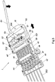
- Figures 1 to 9 show a first embodiment of a tremolo device -1-according to the present invention, arranged on the body -301-of a guitar -300-.
- Said tremolo device -1- is formed by a structural element -10-, such as, for example, a flat structure made of metal plate that supports all of the separate elements comprised by said device -1-.
- Said structure -10- can be secured to the body -301- of the guitar -300- by means of securing elements such as, for example, threaded elements (-11-, -12-) arranged in the longitudinal sides of said structure -10-.
- Said threaded elements (-11-, -12-) may, in some cases, be inserted into pre-existing holes in the guitar provided for securing standard guitar bridges.
- said metal plate structure -10- is secured to the strap button -303- of the guitar -300- by means of a bracket -304-, also made of metal plate, that has an elongated hole -305- and a pin (not shown in the figures) for engaging with a hole -306- (see Figure 5 ) provided in an end of the structure -10-.
- Said elongated hole -305- allows adjustment of the distance between the end of the structure -10- and the strap button -303-, which may vary according to the dimensions of the guitar -300- and the point of location of the device -1-with respect to the guitar -300-.
- the structure -10- comprises, at the end opposite to the hole -306-, two elongated holes -13-, one on each side of the structure -10-, to allow the structure -10- to be secured to the guitar -300- by means of said threaded elements -12-.
- Said elongated holes -13- also allow variable adjustment of said structure -10- according to the dimensions of the guitar -300- and the point of location of the device -1- with respect to the guitar -300-.
- the tremolo device -1- of this first embodiment comprises, in the end portion of the structure -10- nearest to the fingerboard or neck of the guitar -300-, five runners -40-arranged parallel to the longitudinal axis of the structure -10-.
- Each runner -40- is arranged on at least one longitudinal groove (not shown), arranged along the longitudinal axis of each runner -40-, that comprises at least one ball bearing (not shown) which allows the runner -40- to slide with minimal friction relative to its longitudinal axis.
- each runner -40- nearest to the fingerboard or neck of the guitar -300- is provided a saddle -42- on which each string -302- respectively sits.
- a pulley -41- for securing each string -302- to the runner -40-.
- each runner -40- furthest from the fingerboard of the guitar -300- is secured respectively to a rod -43- parallel to the longitudinal axis of the device -1-by means of a coupling element -44-.
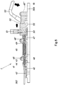
- Said rod -43- as can be seen in Figure 5 , first passes through the through-hole of a first wall -46-, then passes inside a spring -45- arranged between said first wall -46- and a second wall -46'-, and finally said rod -43- passes through the through-hole of said second wall -46'-, and is then attached to an actuating end -47-.
- the string -302-, the runner -40- and the actuating end -47- act together by means of the rod -43-.
- Said rod -43- and the actuating end -47- form the actuation portion that transmits the actuations on each runner -40-.
- the actuating end -47- comprises a hole suitable for the introduction of a pin -50- associated with a push-button -51- of a clutch device that allows the user to select in the device -1- which group of runners -40- will be actuated when the tremolo device -1- is used.
- said spring -45- is arranged between said first wall -46- and said second wall -46'-.
- the ends of said spring -45- are secured respectively to two ferrules (-48-, -49-), each ferrule having a collar with a larger diameter than the rest of the ferrule.
- the diameter of said collars is greater than that of said through-holes of said walls -46-, -46'-, so that the spring -45- is trapped between said walls -46-, -46'-, limiting the possibility of extension of said spring -45-.
- each respective circular section of each ferrule has a suitable diameter to be capable of passing through the through-holes of said walls -46-, -46'-.
- the ferrule -48- in this first embodiment, comprises in its smaller-diameter section a threaded area for engaging with a mating threaded area in the through-hole of the wall -46-. Said ferrule -48- serves as a fixed stop for the spring -45-.
- the smaller-diameter circular section of the ferrule -49- passes through the inside of the through-hole until the collar of said ferrule -49- abuts against the wall -46'-. It should be noted that the rod -43- runs through the inside of the ferrules -47-, -48- and the spring -45- without any contact with said components, and therefore without suffering any friction.
- the location of the spring -45- between two walls (-46-, -46'-) defining two stops makes it possible to limit the travel of the spring -45-, especially when the tremolo device -1- is actuated, ensuring that the spring -45- always works in the compression position, which facilitates the maintenance of the tuning (constant tuning) of the guitar after repeated actuation of the tremolo device -1-.
- the structure -10- also comprises a slide carriage -52- arranged as a continuation of the described assembly.
- Said slide carriage -52- can move through a limited travel between said second wall -46'- and a third wall -46"- along two lateral guides (-521-, -522-) parallel to the transverse axis of said slide -52-.
- said slide carriage -52- comprises push-buttons -51- corresponding to each runner -40- to allow individual selection of each string -302- that it is desired to actuate with the tremolo device -1-.
- the tremolo device -1- is adjusted so that the pins -50- of the respective push-buttons -51- are arranged just above the respective holes of the respective securing elements -47-corresponding to each string -302-.
- a transverse shaft -55- is arranged between the lateral guides (-521-, -522-) .
- On said shaft -55- is provided a cam -54- which moves the slide carriage -52- by pushing, by the actuation of a lever -53-, in both directions along the path provided by the lateral guides (-521-, -522-).
- FIGS. 1 and 2 show the tremolo device -1- according to a first embodiment in the resting state.
- each string -302- secured to its respective pulley -41- of its respective saddle -42-, pulls, in turn, on the runner -40-, the rod -43- and the actuating end -47- corresponding to each string -302-.
- the actuating end -47- abuts, due to its smaller-diameter circular section, with the ferrule -49- of the end of the spring -45-, establishing an equilibrium between said string -302- and the corresponding spring -45-.
- a point of equilibrium is achieved that maintains the tuning of the strings and makes it possible to act directly on the arm -53- of the tremolo device -1- without any need to lock and unlock said device -1-.
- Figures 3 to 5 show a first mode of operation (actuation of the device -1- to increase the tension of the strings -302-) of the tremolo device -1- according to the present invention.
- this mode of operation only the operation of the push-button -51- will be explained, while the push-buttons -56- and -57- also selected, as shown in Figure 5 , also work in the same way as the push-button -51-.
- the cam -54- moves the slide carriage -52-, guided by its lateral guides (-521-, -522-), towards the wall -46"-.
- the push-button -51- by means of its respective pin -50-, moves the actuating end -47-, and consequently the rod -43- and the runner -40-, in the direction of the wall -46"-, further tensioning the string -302-.
- Figures 6 to 8 show a second mode of operation (actuation of the device -1- to decrease the tension of the strings -302-) of the tremolo device -1- according to the present invention.
- this second mode of operation only the operation of the push-button -51- will be explained, while the push-buttons -56- and -57- also selected, as shown in Figure 6 , also work in the same way as the push-button -51-.
- the cam -54- moves the slide carriage -52-, guided by its lateral guides (-521-, -522-), towards the wall -46'-.
- the push-button -51- by means of its respective pin -50-, moves the actuating end -47- in the direction towards the wall -46-.
- the actuating end -47- on one hand, causes the shaft -43- and the runner -40- to move in the direction towards the fingerboard of the guitar -300-, resulting in a slackening of the string -302-, and, on another hand, said actuating end -47- pushes the ferrule -49-, causing the spring -45- to be compressed.
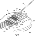
- Figures 10 to 17 show a second embodiment of a tremolo device -2- according to the present invention, arranged on the body -301- of a guitar -300-.
- Said tremolo device -2- is formed by a structural element -20-, such as, for example, a flat structure made of metal plate that supports all of the separate elements comprised by said device -2-.
- Said structure -20- can also be secured to the body -301-of the guitar -300- in the same way (by means of a bracket, threaded elements and elongated holes) as in the first embodiment of the device -1-, allowing variable adjustment of said structure -20- according to the dimensions of the guitar -300- and the point of location of the device -2- with respect to the guitar -300-.
- the tremolo device -2- comprises five longitudinal -70- platens arranged parallel to the longitudinal axis of the structure -20-.
- Each platen -70- is arranged on at least one longitudinal groove (not shown), arranged along the longitudinal axis of each platen -70-, that comprises ball bearings (not shown) which allow the platen -70- to slide with minimal friction relative to its longitudinal axis.
- each longitudinal platen -70- On the end of each platen -70- nearest to the fingerboard or neck of the guitar -300- a saddle -75- is provided on which each string -302- respectively sits by means of its corresponding pulley for securing each string -302-.
- the opposite end of each longitudinal platen -70- comprises a hole suitable for the introduction of a pin -81- of a push-button -66- of a clutch device that allows the user to select in the device -2- which platens -70- will be actuated when the tremolo device -2- is used.
- each platen -70- and above each of them is arranged a slide carriage -60- with springs -71-, in such a way that each spring -71- is arranged above each platen -70-.
- Each spring -71- is arranged between a first wall -61- and a second wall -62- of the slide carriage -60-.
- the ends of said spring -71- are also secured respectively to two ferrules (-73-, -68-), each ferrule having a collar with a larger diameter than the rest of said ferrule. The diameter of the collars is greater than that of said through-holes of said walls (-61-, -62-), so that each spring -71- is trapped between said walls (-61-, -62-).
- each respective circular section of each ferrule has a suitable diameter to be capable of passing through the through-holes of said walls (-61-, -62-) .
- the ferrule -73- comprises in its smaller-diameter section a threaded area intended to engage with a mating threaded area in the through-hole of the wall -61-. Said ferrule -73- serves as a fixed stop for the spring -71-.
- the smaller-diameter circular section of the ferrule -68- can pass through the inside of the through-hole of the wall -62- of the slide carriage -60- until a larger-diameter collar abuts against the wall -62-.
- said ferrule -68-, at its smaller-diameter circular section end is threaded into another ferrule -63-, which serves, in turn, as a stop with a quadrangular projection -64- arranged on the platen -70- between said ferrule -63- and the push-button -66-.
- the location of the spring -71- between two walls (-61-, -62-) defining two stops makes it possible to limit the travel of the spring -71-, especially when the tremolo device -2- is actuated, ensuring that the spring -71- always works in the compression position, which facilitates the maintenance of the tuning (constant tuning) of the guitar after repeated actuation of the tremolo device -2-.
- the structure -20- also comprises a slide carriage -80- arranged as a continuation of the quadrangular projection -64-.
- Said slide carriage -80- can move through a limited travel between the walls (-62-, -90-), along two lateral guides (-621-, -622-) parallel to the transverse axis of said slide carriage -80-.
- said slide carriage -80- comprises push-buttons -65- corresponding to each platen -70- to allow individual selection of each string -302- that it is desired to actuate with the tremolo device -2-.
- the tremolo device -2- is adjusted so that the pins -80- of the respective push-buttons -65- are arranged just above the respective holes in the ends of the platens -70- corresponding to each string -302-.
- a transverse shaft is arranged between the lateral guides (-621, -622-).
- a cam -91- is provided which moves the slide carriage -80- by pushing, by the actuation of a lever -53-, in both directions on the lateral guides (-621-, -622-).
- Figures 10 and 11 show the tremolo device -2- according to a second embodiment and in the resting state.
- each string -302- secured to its respective pulley of its respective platen -70-, pulls, in turn, on said platen -70- along its entire length, and consequently also pulls on the quadrangular projection -64-arranged on the platen -70-.
- said quadrangular projection -64- abuts with the joined ferrules (-62-, -63-), establishing an equilibrium between said string -302- and the corresponding spring -71-, thus achieving a point of equilibrium that maintains the tuning of the strings and makes it possible to act directly on the arm -53- of the tremolo device -2- without any need to lock and unlock said device -2-.
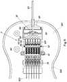
- Figures 12 to 14 show a first mode of operation (actuation of the device -2- to increase the tension of the strings -302-) of the tremolo device -2- according to the present invention.
- first mode of operation actuation of the device -2- to increase the tension of the strings -302-
- the push-buttons -65- and -67- also selected, as shown in Figure 12 , also work in the same way as the push-button -66-.
- the cam -90- moves the slide carriage -80-, guided by the lateral guides (-621-, -622-), towards the wall -90-.
- the push-button -66- by means of its respective pin -81-, moves the platen -70- in the direction of the wall -90-, further tensioning the string -302-.
- Figures 15 to 17 show a second mode of operation (actuation of the device -2- to decrease the tension of the strings -302-) of the tremolo device -2- according to the present invention.
- this mode of operation only the operation of the push-button -66- will be explained, while the push-buttons -65- and -67- also selected, as shown in Figure 15 , also work in the same way as the push-button -66-.
- the cam -90- moves the slide carriage -80-, on its lateral guides (-621-, -622-), towards the wall -62-.
- the push-button -66- by means of its respective pin -81-, moves the platen -70- in the direction of the wall -62-.
- the quadrangular projection -64- joined to the platen -70- causes, on one hand, said platen to move in the direction towards the fingerboard of the guitar -300-, resulting in a slackening of the string -302-, and, on another hand, said quadrangular projection -64-pushes the joined ferrules (-62-, -63-), causing the spring -71- to be compressed.
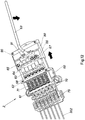
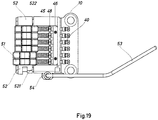
- Figures 18 to 24 show a third embodiment of the device of the present invention, which has more compact dimensions.
- Figures 18 to 24 is similar to that of Figures 1 to 8 with regard to the arrangement of the runners -40-, the runner actuating rod -43-, the springs -45- and the walls -46-, -46'-, but with differences with regard to the push-buttons -51- of the clutch system, which in this case are sliding selectors, the clutch system itself, the spatial arrangement of the arm -53-, the slide carriage -52- and the structure of the clutch.
- the arm -53- is located laterally with respect to the device, actuating, by means of a cam system -54-, a slide carriage -52-, which moves by sliding along the lateral guides -521-, -522-.
- This arrangement allows the slide carriage -52- to be arranged beneath the push-buttons -51- that allow the user to individually select which strings will be subjected to the action produced by the actuation of the arm -53-.
- the selection and deselection of which strings will be acted upon by the tremolo or vibrato is carried out by sliding the push-buttons -51-, which activate/deactivate the clutch system, which is described with reference to Figures 21 to 24 .
- the actuating end or actuating member -47'- takes the form of a sleeve that surrounds the rod -43-.
- the rod is connected to the runner -40- that receives the string (not illustrated), having in an intermediate position the system of springs -45-and stops -46-, -46'-, which is similar to that of the previous embodiments and therefore will not be described in detail.
- the actuating member -47'- has a series of holes -471- arranged peripherally with respect to a transverse cross-section. A ball -472- is housed in said holes -471-.
- the rod -43- also has an indentation or recess -431- to receive the ball -471-.
- the recess -431- will be an indentation that covers the entire perimeter of the rod, but a specific recess could be created for each ball -472-.
- the ball -472-, the hole or holes -471-, the housing or housings -512- and the recess or recesses -431- are dimensioned so that each ball can be completely housed either between a hole -471- and a recess -512- or between a hole -471-and a housing -512- and so that, in addition, the ball is capable of moving from one position to the other under the pushing forces produced by the different actuations of the system, such as the actuation of the arm that in turn moves the slide carriage -52-, or the actuation of the push-button -51-.
- Figure 21 shows the system in the declutched position and without any actuation of the tremolo.
- the push-button -51- has an appendage -511- with a hole that surrounds the actuating member -47'-.
- the push-button or actuator -51- can slide relative to the actuating member -47'- in order to move from a clutched position to a declutched position.
- the appendage -511- of the push-button -51- has a housing -512-that coincides in position with the holes -471- of the actuating member -47'- and also with the recess -431- of the rod -43-.
- the ball -472-located on top of the rod due to the action of gravity, is completely housed in the hole -471- of the actuating member -47- and the recess -431- of the rod -43-. It should be noted that the action of gravity may arrange the lower ball -472-in the housing -512-.
- the actuating member -47'- is joined integrally to the slide carriage -52-, which in turn is actuated by the arm (not shown in Figure 21 ).
- the actuating member -47'- moves with the slide carriage -52-.
- the movement of the actuating member pushes the ball or balls -472-.
- the balls -472- roll until they are completely housed between the housing -512- and the corresponding hole -472-, rolling on top of the rod.
- the slide carriage, -52-, actuating member -47- and push-button -51- move together as a unit, but the rod -43- remains in its place and does not transmit the movement to the runner -40-.
- the runner -40- has no ball bearings and is situated in the air.
- the spring is located between two stops, in such a way that it always works under compression, i.e. the greatest working length that the device allows it is less than its natural length at rest. This ensures that the properties of the springs are not modified by deformations caused by extensions that result in spring lengths greater than their natural length at rest. This embodiment can be created regardless of whether or not a system exists for selecting which string or strings will be actuated by the tremolo.
Landscapes
- Physics & Mathematics (AREA)
- Engineering & Computer Science (AREA)
- Acoustics & Sound (AREA)
- Multimedia (AREA)
- Stringed Musical Instruments (AREA)
- Electrophonic Musical Instruments (AREA)
Applications Claiming Priority (2)
| Application Number | Priority Date | Filing Date | Title |
|---|---|---|---|
| ES201430161A ES2510966B1 (es) | 2014-02-07 | 2014-02-07 | Dispositivo para alterar la tensión de las cuerdas en un instrumento musical con cuerdas |
| PCT/ES2015/070036 WO2015118195A1 (es) | 2014-02-07 | 2015-01-21 | Dispositivo para alterar la tensión de las cuerdas en un instrumento musical con cuerdas |
Publications (2)
| Publication Number | Publication Date |
|---|---|
| EP3104366A1 true EP3104366A1 (de) | 2016-12-14 |
| EP3104366A4 EP3104366A4 (de) | 2017-09-13 |
Family
ID=52471960
Family Applications (1)
| Application Number | Title | Priority Date | Filing Date |
|---|---|---|---|
| EP15745908.2A Withdrawn EP3104366A4 (de) | 2014-02-07 | 2015-01-21 | Vorrichtung zur änderung der spannung der saiten von saitenmusikinstrumenten |
Country Status (8)
| Country | Link |
|---|---|
| US (1) | US9653049B2 (de) |
| EP (1) | EP3104366A4 (de) |
| JP (1) | JP6444423B2 (de) |
| KR (1) | KR20160135712A (de) |
| CN (1) | CN105981097B (de) |
| ES (1) | ES2510966B1 (de) |
| RU (1) | RU2016134285A (de) |
| WO (1) | WO2015118195A1 (de) |
Families Citing this family (9)
| Publication number | Priority date | Publication date | Assignee | Title |
|---|---|---|---|---|
| US9905210B2 (en) | 2013-12-06 | 2018-02-27 | Intelliterran Inc. | Synthesized percussion pedal and docking station |
| US11688377B2 (en) | 2013-12-06 | 2023-06-27 | Intelliterran, Inc. | Synthesized percussion pedal and docking station |
| US10741155B2 (en) | 2013-12-06 | 2020-08-11 | Intelliterran, Inc. | Synthesized percussion pedal and looping station |
| US12159610B2 (en) | 2013-12-06 | 2024-12-03 | Intelliterran, Inc. | Synthesized percussion pedal and docking station |
| USD778981S1 (en) * | 2016-01-27 | 2017-02-14 | S7G Usa, Llc | Guitar |
| DE112018000413T5 (de) * | 2017-01-17 | 2019-10-10 | Drum Workshop, Inc. | Schlagzeug mit verstellbarer Hilfsvorrichtung |
| JP7193167B2 (ja) | 2017-08-29 | 2022-12-20 | インテリテラン,インク. | マルチメディアを記録してレンダリングするための装置、システム、及び方法 |
| FR3073658B1 (fr) * | 2017-11-12 | 2020-04-17 | Eric Majerowicz | Dispositif de vibrato pour instrument de musique a cordes |
| IT201900018467A1 (it) * | 2019-10-10 | 2021-04-10 | Riviera Srl Unipersonale | Dispositivo di accordatura, dispositivo di fissaggio di corda di chitarra, kit di accordatura e ponte per chitarra. |
Family Cites Families (16)
| Publication number | Priority date | Publication date | Assignee | Title |
|---|---|---|---|---|
| US2949806A (en) * | 1958-09-08 | 1960-08-23 | Thomas B Turman | Individual string tone changer for guitars |
| JPS63234295A (ja) * | 1987-03-23 | 1988-09-29 | ヤマハ株式会社 | 弦楽器の弦張力調整装置 |
| US4928564A (en) * | 1988-08-22 | 1990-05-29 | Borisoff David J | Apparatus and method for stabilizing a tremolo on a musical instrument such as a guitar |
| JPH0264698A (ja) * | 1988-08-31 | 1990-03-05 | Yukio Ishikawa | 弦楽器におけるトレモロユニットの各別調整装置 |
| US4944208A (en) * | 1989-04-21 | 1990-07-31 | Kusek Peter A | Guitar with adjustable tremolo |
| US5083492A (en) * | 1989-10-04 | 1992-01-28 | Joachim Gorr | Guitar tremolo system |
| JPH05188927A (ja) * | 1992-01-13 | 1993-07-30 | Teyuun Gitaa Technol Kk | ギター用トレモロ装置 |
| US5477765A (en) * | 1994-03-24 | 1995-12-26 | Dietzman; William C. | Vibrato unit for a guitar |
| US5435219A (en) * | 1994-08-08 | 1995-07-25 | Huff; Richard E. | Vibrato assembly for stringed instruments |
| US5847297A (en) * | 1996-11-19 | 1998-12-08 | Fisher, Iv; Charles H. | Tremolo with spaced saddles for a stringed musical instrument |
| US5939653A (en) * | 1998-10-20 | 1999-08-17 | Chang; I-Ping | Bridge and tremolo arm assembly for an electric guitar |
| US6384311B1 (en) * | 2001-02-12 | 2002-05-07 | Jose G. Cota | Guitar having tremolo device on each string thereof |
| JP3655218B2 (ja) * | 2001-06-26 | 2005-06-02 | 星野楽器株式会社 | 弦楽器用トレモロ装置 |
| WO2007081273A1 (en) * | 2006-01-16 | 2007-07-19 | Sonoinvent Ab | Tremolo means |
| WO2010030959A2 (en) * | 2008-09-11 | 2010-03-18 | Del Capo Company | Capo |
| US20120132055A1 (en) * | 2010-11-30 | 2012-05-31 | Brinkley Jr Gary N | Tremolo device |
-
2014
- 2014-02-07 ES ES201430161A patent/ES2510966B1/es not_active Expired - Fee Related
-
2015
- 2015-01-21 RU RU2016134285A patent/RU2016134285A/ru not_active Application Discontinuation
- 2015-01-21 CN CN201580007695.9A patent/CN105981097B/zh not_active Expired - Fee Related
- 2015-01-21 EP EP15745908.2A patent/EP3104366A4/de not_active Withdrawn
- 2015-01-21 KR KR1020167024107A patent/KR20160135712A/ko not_active Ceased
- 2015-01-21 US US15/117,170 patent/US9653049B2/en not_active Expired - Fee Related
- 2015-01-21 JP JP2016550563A patent/JP6444423B2/ja not_active Expired - Fee Related
- 2015-01-21 WO PCT/ES2015/070036 patent/WO2015118195A1/es not_active Ceased
Also Published As
| Publication number | Publication date |
|---|---|
| JP6444423B2 (ja) | 2018-12-26 |
| CN105981097A (zh) | 2016-09-28 |
| WO2015118195A1 (es) | 2015-08-13 |
| ES2510966A1 (es) | 2014-10-21 |
| US20160351173A1 (en) | 2016-12-01 |
| KR20160135712A (ko) | 2016-11-28 |
| RU2016134285A (ru) | 2018-03-13 |
| CN105981097B (zh) | 2020-06-16 |
| ES2510966B1 (es) | 2015-08-11 |
| JP2017505463A (ja) | 2017-02-16 |
| EP3104366A4 (de) | 2017-09-13 |
| US9653049B2 (en) | 2017-05-16 |
Similar Documents
| Publication | Publication Date | Title |
|---|---|---|
| US9653049B2 (en) | Device for altering the tension of the strings of a stringed musical instrument | |
| US7014599B2 (en) | Selectable force exercise machine | |
| JP5080812B2 (ja) | 戸棚の跳ね戸の調整アーム駆動装置 | |
| US6595899B2 (en) | Stepping exerciser | |
| US7587958B2 (en) | De-Cel dampener method and apparatus | |
| EP0916570A3 (de) | Einstellvorrichtung für Bowdenzug | |
| ATE410357T1 (de) | Betätigungsvorrichtung für eine fahrradgangschaltung | |
| ATE467974T1 (de) | Gleitmechanismus für tragbare geräte | |
| SE466574B (sv) | Tvaadelad vaexelspak med vibrationsdaempning | |
| US9251768B2 (en) | Shoulder strap operated pitch changing means for stringed instruments | |
| JPH0564804B2 (de) | ||
| US10215220B2 (en) | Bowden cable with combined splitter and compensator | |
| JP4481429B2 (ja) | 手動変速機の誤操作防止機構 | |
| HK1228087A1 (en) | Device for altering the tension of the strings of a stringed musical instrument | |
| US3293975A (en) | Plucking mechanism for musical instrument | |
| AU2018355020B2 (en) | Device and method for damping of aliquot tones | |
| CN101833947B (zh) | 电子键盘乐器的踏板装置 | |
| DE502004008720D1 (de) | Variable Ventilsteuerungseinrichtung | |
| US4018103A (en) | Control linkage mechanism | |
| FR2826451B1 (fr) | Dispositif de simulation d'une commande de passage de vitesses d'une boite de vitesses manuelle, constituant un simulateur passif pour tests ergonomiques | |
| US6729640B1 (en) | Device for influencing flexing movements of a ski | |
| KR100597362B1 (ko) | 차량의 변속레버 길이조절장치 | |
| KR100877782B1 (ko) | 변속레버 방진기구 | |
| KR100643996B1 (ko) | 수동변속기의 변속기구 | |
| KR101164990B1 (ko) | 자전거 변속장치 |
Legal Events
| Date | Code | Title | Description |
|---|---|---|---|
| PUAI | Public reference made under article 153(3) epc to a published international application that has entered the european phase |
Free format text: ORIGINAL CODE: 0009012 |
|
| STAA | Information on the status of an ep patent application or granted ep patent |
Free format text: STATUS: REQUEST FOR EXAMINATION WAS MADE |
|
| 17P | Request for examination filed |
Effective date: 20160804 |
|
| AK | Designated contracting states |
Kind code of ref document: A1 Designated state(s): AL AT BE BG CH CY CZ DE DK EE ES FI FR GB GR HR HU IE IS IT LI LT LU LV MC MK MT NL NO PL PT RO RS SE SI SK SM TR |
|
| AX | Request for extension of the european patent |
Extension state: BA ME |
|
| DAX | Request for extension of the european patent (deleted) | ||
| A4 | Supplementary search report drawn up and despatched |
Effective date: 20170810 |
|
| RIC1 | Information provided on ipc code assigned before grant |
Ipc: G10D 3/14 20060101AFI20170804BHEP Ipc: G10D 1/08 20060101ALI20170804BHEP |
|
| STAA | Information on the status of an ep patent application or granted ep patent |
Free format text: STATUS: EXAMINATION IS IN PROGRESS |
|
| 17Q | First examination report despatched |
Effective date: 20200403 |
|
| STAA | Information on the status of an ep patent application or granted ep patent |
Free format text: STATUS: THE APPLICATION IS DEEMED TO BE WITHDRAWN |
|
| 18D | Application deemed to be withdrawn |
Effective date: 20210803 |